

Jeffrey Harris Tommy Kimbrell

Boeing 737-300 lifted by a crane
Aircraft Assembly Line Crane Control
Project team member(s): Jeffery Harris, Tommy Kimbrell
Abstract
In airplane manufacturing, large parts of the assembly are often moved about the plant floor via overhead cranes. This projects looks to increase the efficiency of these large, crane operated construction lines using feedback control. Our goal for this project is to model an example crane system, and design to respond with minimal steady state error, overshoot and settling time to help increase efficiency of aircraft production. The primary design objectives are to minimize settling time (for speed of the assembly line) while keeping our max overshoot under 10% (for factory safety) and our max input force under the max operating force of our crane. To achieve this, we designed a PD controller.
We decided to solve this problem using a PD controller. Due to the 4th order nature of this system, the usual equations approximating After many iterations, we eventually chose values for
Advanced Feature: We are modeling a 4th order system.
Introduction
Cranes are an important part of many manufacturing operations, moving heavy loads around a production line. One example is the use of cranes in aircraft assembly lines where large aircraft parts assembled on different lines need to be brought together for final construction. A major setback in the efficiency of these cranes is the inherent payload oscillations, making the precise location control needed to not damage the airplane, very slow. Our goal is to make a crane's movement more efficient through the use of a well designed control system.
Plant Model
For our problem we look to move a Boeing 737 cabin along a construction line so it can be attached to other components of the plane. We aim to construct a control law that will allow us to move the cabin a max distance of 100 m in the hanger, with less than 10% overshoot and settling in under 60s. Our model assumes a strictly liner, 1-D motion of the crane "cart", and that the load will only swing a small amount (small angle approximation).
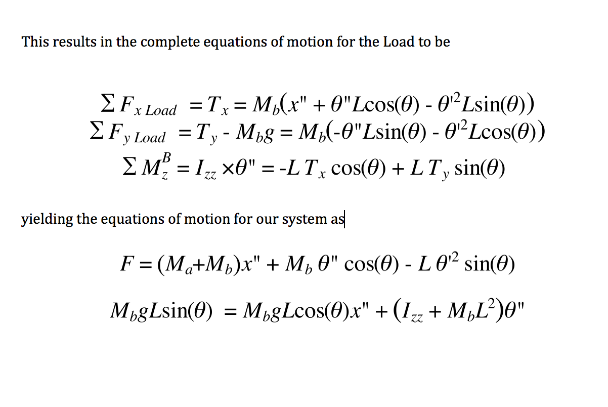
Using a free body diagram, we modeled the system and derived the equations of motion. These assume that the forces of friction and air resistance are negligible compared to the force applied to the system, which is 68 kN (derived in the "control design" section).
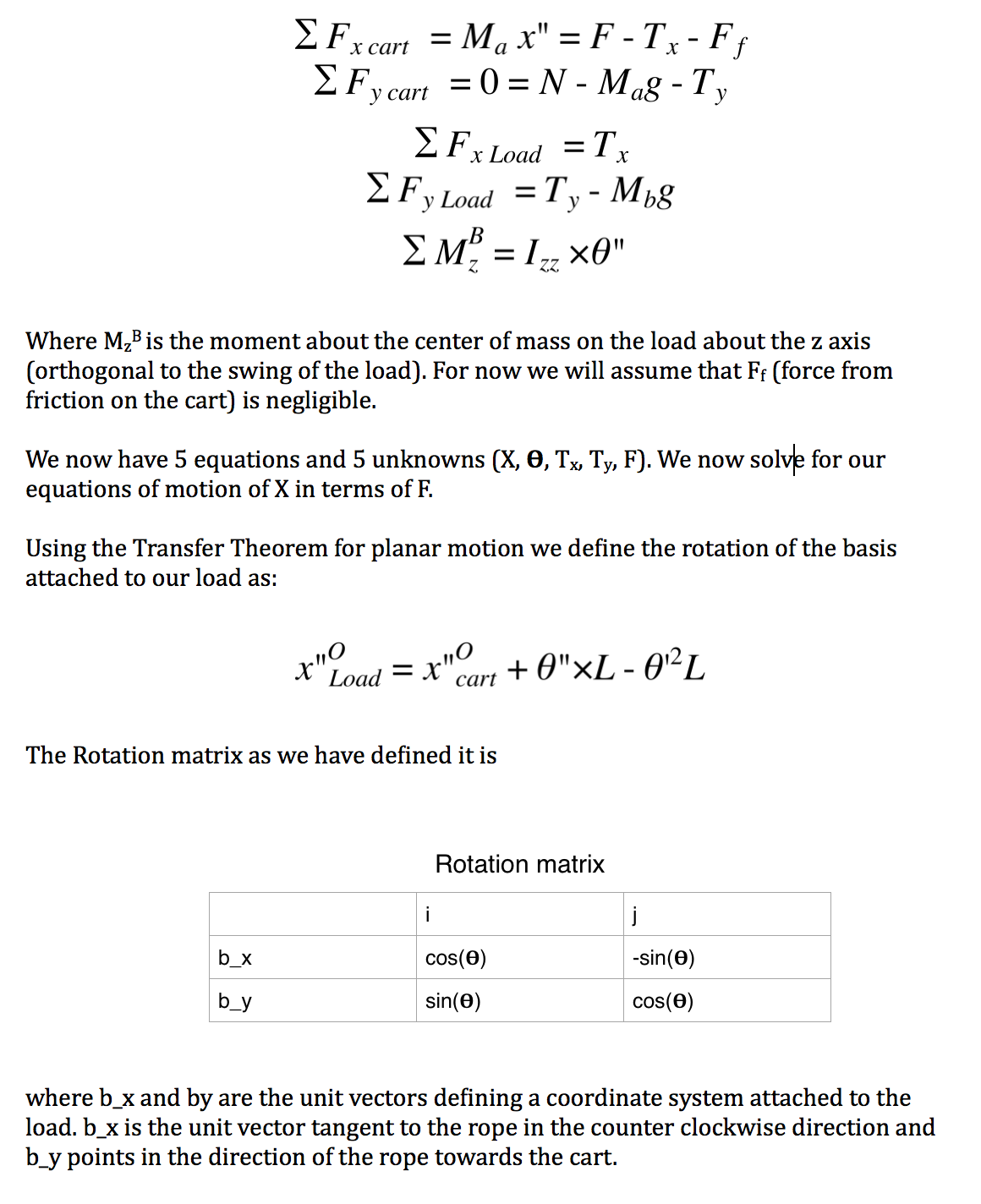
This yields the system's coupled Time Domain Equations and S Domain Equation of Motion:
The Open Loop Block Diagram for this system with an input force and output position
Below are the symbols used in our equations of motion. The mass of the trolley was found from a part drawing from American Crane (Attached at the bottom). We used the known mass of a Boeing 737 to estimate the mass of the main cabin. From this and the length of the cabin we modeled the cabin as a rod and found the moment of inertia around the center. Finally, the length from trolley to airplane was estimated from the known height of the Boeing factory.

The open loop response to an impulse input is unstable, accelerating the load parabolically (as we expect with any constant force on a load) and drives the position of the load to infinity. This does not help us build airplanes. We need a controller to regulate when to stop applying forward force and when to begin breaking.
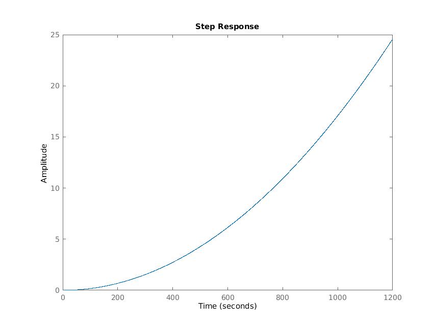
(MatLab code attached below)
Control Design
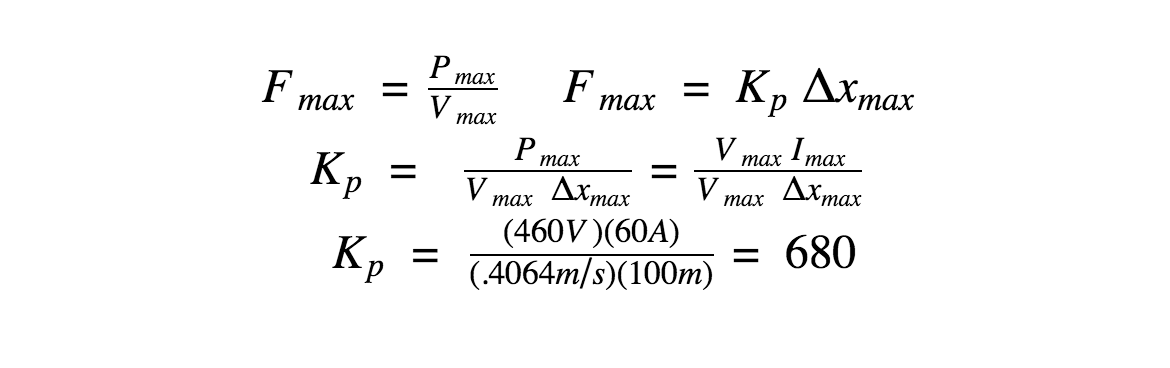
We choose to use a PD controller for the design of our crane operation. The PD controller was chosen because it is the simplest controller that would stabilize the system and help us quickly meet our overshoot requirements. In order to have the fastest response possible, we want to maximize our input force into the system we maximize Kp within our physical limits. Looking at the American Crane Trolley data sheet (attached at the bottom) we found that the trolley's max speed is 80 fpm (.4064 m/s), the max voltage in is 460 V and our max current is 60 A. From this we calculate...
Next, we looked at our open loop bode plot (below). A PD controller will add a zero to the LHP, moving forcing our poles into the LHP. Since we know Kp = 680, we now must find the Kd that will put our overshoot under 10%. Adding a slower pole will move the poles of our plant further into the LHP while also damping our system. Through trial and error we found that in order to meet our overshoot requirements, we must use our PD controller to critically damp our system as you can see in the root locus plot with our controller.

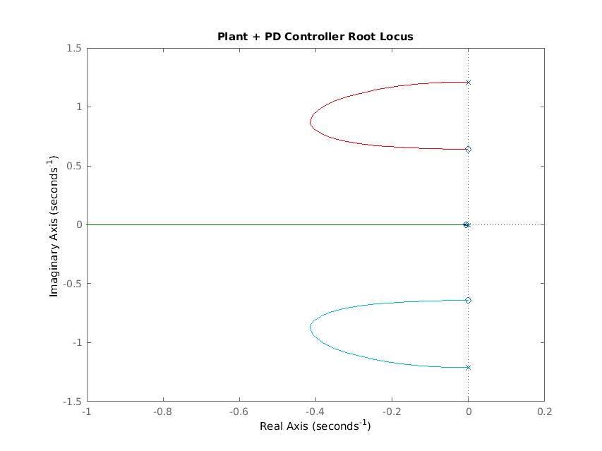
From our root locus plot we find that a PD controller with Kd = 102,000 and Kp = 680 would give our system less than 10% overshoot while being within the physical limits of our trolly.
Our controller gives the following block diagram..

With our PD controller transfer function being...
Results
Our PD controller was able to make our system stable and within our design criteria. Our closed loop response to a 1m step input is shown below.
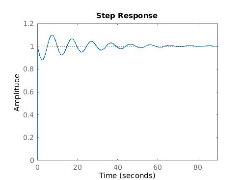
From our plot above, we see that our system now has a max overshoot of 9.95%, less than our 10% design requirement. Also notable is that our settling time for a 1m step input is 42s. Scaling this up to a 100m step would means it would take 70 min to move the plane cabin. Since the plane cabin should not be moved more than one time over the course of the plane's construction, taking 70 minutes to move is very reasonable in its 10 construction cycle. Other notable information about the system include...

Conclusions
The controlled system meets the design parameters. As we experimented, we found that by increasing the value of Kd, we could further decrease maximum overshoot. This is good, since for a step input of 100 meters, the largest step input we said would be allow, this design still allows for an overshoot of 10 meters which is a lot. The other parameter worth mentioning is the settling time. It would take this system over an hour to settle for a step input of 100 m. This is quite a long time, but if we are really moving something this big, slower is probably safer for both man and material.
If we were to continue working on this project, the first thing we would change would be making the input motor torque instead of Force. We do not actually control the force on a motor, but rather the voltage to it which is closely related to the torque.
The second major change we would make is to include friction in the cart. this would add damping in the plant, making it more realistic and require a smaller Kd.
The las major change we would implement is to use a Lead compensator rather than a PD controller. This is because in a digital system (as this would be with any readily available and accurate position sensor) derivative control is not physically possible. Lead compensators can achieve largely the same effect.
Acknowledgments
Adam Leeper
Paul Mitiguy
Files
Code and Simulink models should be linked here. You can upload these using the Attach command.
- File 1: Attach:KimbrellHarris_Project.pdf
Matlab Code - File 2 attached and described here
- File 3 attached and described here
References
List the referenced literature, websites, etc. here. "Interfaces and Control Systems for Intuitive Crane Control" by Chen Peng https://smartech.gatech.edu/bitstream/handle/1853/31782/peng_chen_chih_200912_mast.pdf
Boeing 737 Data https://en.wikipedia.org/wiki/Boeing_737_Next_Generation
American Crane Trolley Specs Attach:TrolleyDocumentation.pdf