

Robert Sun Christian Castellanos

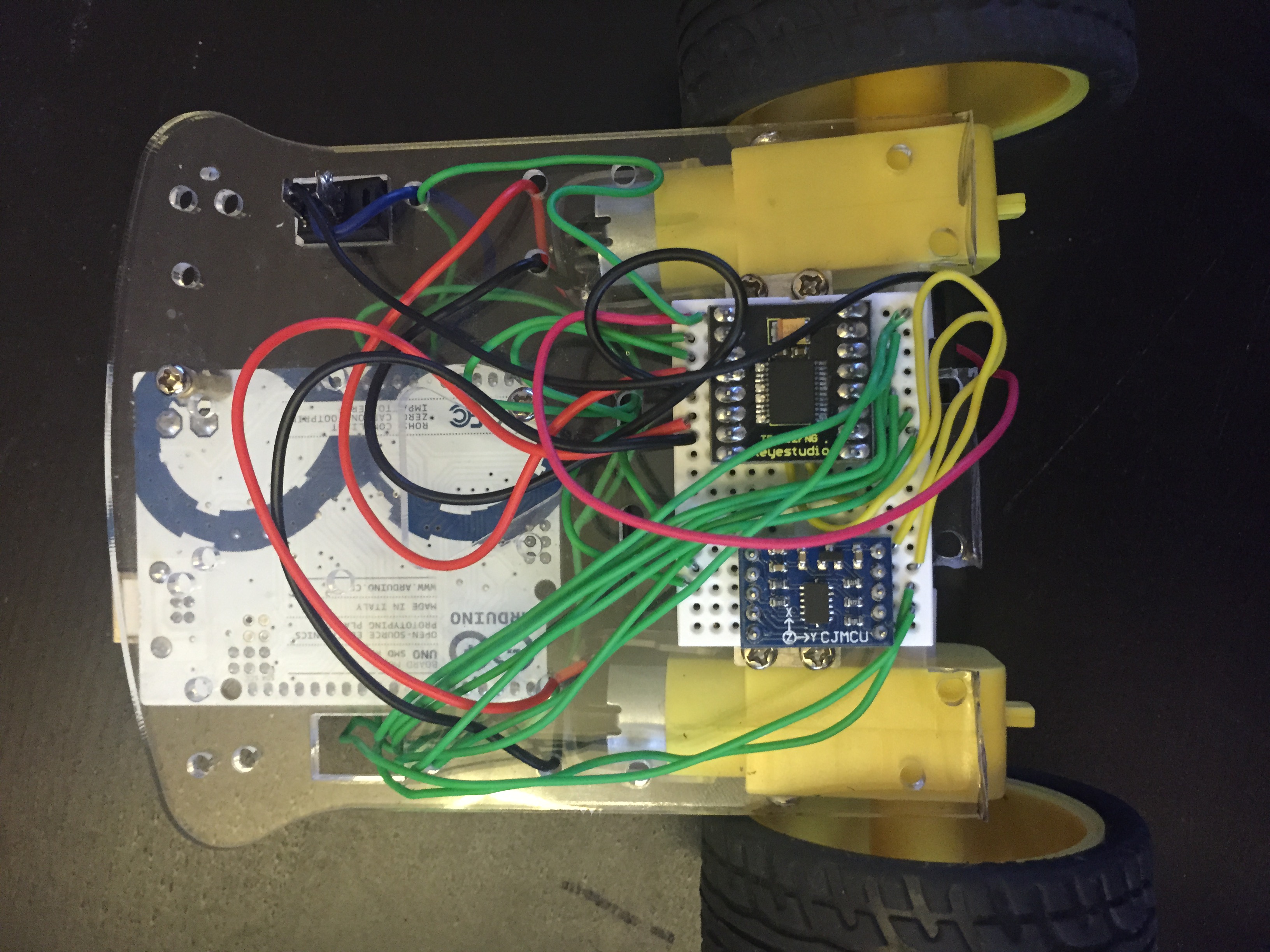
The physical model of the system:
A tiny Arduino Segway!
Modeling Feedback Control of Segway (Single Axis 2-Wheel Upright Vehicle)
Project team member(s): Robert Sun and Christian Castellanos
Abstract
The plant we are trying to control is similar to an inverted pendulum - we're attempting to maintain the pendulum vertically upright despite gravity and other physical disturbances. This is similar to the inverted pendulum on a cart; however, the control problem is radically different. In order to maintain the upright position of the pendulum, we have to control the position and angle of the cart with motors at the rotary axis; and we do this by regulating the voltage applied to the motors (which affects motor torque) with PID - rather than simply controlling the position and velocity of the cart. While implementing the discrete version of the controller on an Arduino, most of the simulation results will be invalid and the Kp, Ki, and Kd values will need to be readjusted and retuned for the proper control of unknown motors and electrical characteristics. In the end, after facing numerous sensor and motor issues, we were able to make the physical system stand up decently well, but would have changed quite a bit about the system in order to make the control problem easier.
!!!Advanced Feature
We intend to model the nonlinearities of the inverted pendulum as well as create a small-scale, physical implementation of a Segway. Since we plan on making small-scale Segway, our parameters for the plant model and controller will reflect those, rather than that of a real Segway. We've also simulated the non-linear system with a Simulink model.
Introduction
The inverted pendulum on a cart is one of the quintessential control problems, and as electrical engineers, we wanted to create hardware/a physical system that encapsulates the principles of feedback control design that we learned in this class. We wanted knowledge we've acquired from EE classes to provide our own spin on it, and chose to create a miniature Segway. We plan to build a working model of the control system and witness the robustness and disturbance rejection of our system. It's important to understand the physics and dynamics of the physical system as well as the electromechanical characteristics of motors in order to properly control the vehicle. For those who have not heard of a Segway before, the wikipedia article is attached below.
Plant Model

We have two stages of the plant model. The first stage takes a voltage as an input and the motors converts voltage to torque. The next stage are the equations of motion where the torque of the motor drives an inverted pendulum model. The torque drives the acceleration of the angle at the base of the pendulum and we try to control it vertically upright. We can then measure what the angle of the pendulum is at with a gyroscope sensor from the vertical and have feedback control on the sensor values to motor voltage. When analyzing the plant model however, it is sufficient to just concern oneself with the equations of motion for motor torque combined with the effect of gravity on the moments of inertia of the pendulum. Since Kp values can be adjusted to correct for the relatively linear voltage to torque model, it is necessary to detail over the motor model. It might be effective to estimate the model with motor specifications and use it to guess realistic bounds for the Kp, Ki, and Kd.
Our plant model is given below:

m = mass of the entire object, given in kg. Our robot weighted .352 kg.
g = gravity. Gravity is 9.8 m/s2.
l = distance from the center of the axis to the center of mass, given in meters. We measured our center of mass as being .04 m.
b = damping coefficient (assuming linear damping as proportional to angular velocity). Deriving this would have been unreasonable. We felt that .1 was a good enough estimation for our system.
Theta = Angle between the vertical axis (upright position) and the rod.
No exact Laplace transform exists for our plant model since we wish to model it with the nonlinearity (that is, we will not claim that  ).
).
The derivation of this is as follows:
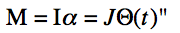
The sum of the moments is equal to the moment of inertia times the angular acceleration of the body. Here, we assume that all of the moments are about the center of mass of the particle at the end of the rod. We thus assume that

The inertia is equal to the mass of object times the rod length squared.
Taking into account linear damping (b), we thus sum the moments:
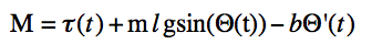
Since we know that M = I * angular acceleration = J * angular acceleration, we can thus rewrite the above equation:

Re-arranged in terms of torque on one side of the equation and theta on the other, we thus have:
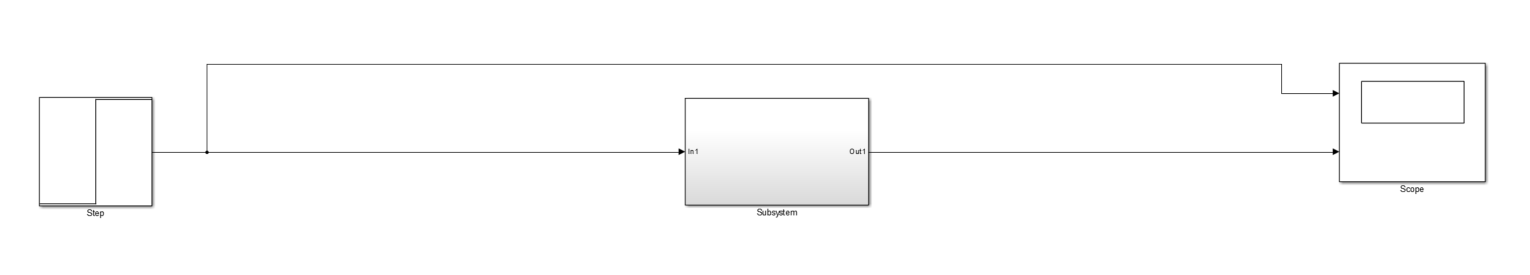
A Simulink model shows how the open loop plant model responds to a step input of 1 N-m of external torque being applied to the plant. We see it simply diverges out of control very fast as the plant just "falls" onto a table. In this case, there is nothing to stop it so it seems like it spins forever.
Here is the overall Simulink model:
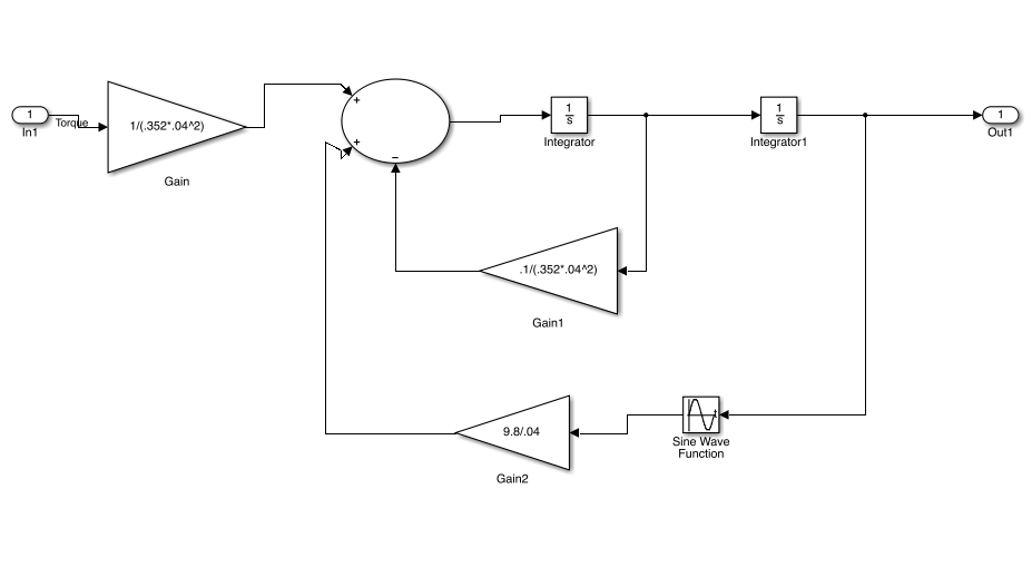
And the subsystem (dynamics for pendulum) inside:
And the response to a step input:

The plant blows up without a controller. A controller is necessary to controller the angle and prevent it from tipping over.
Control Design
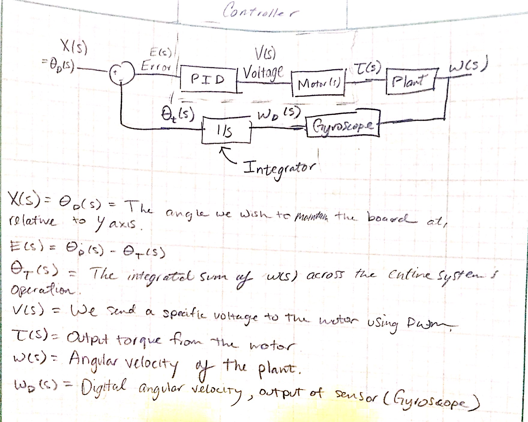
CONTROLLER APPROACH Our physical system requires a gyroscope for implementation. Gyroscopes only measure the angular velocity of a given system; that is, the speed at which Θ(s) is changing.
Our reference input, X(s) = 0; that is, we want the rod/board to remain upright as we apply a voltage to the motor, which in turn generates a torque that's applied to the plant and moves the Segway.
Plant outputs angular velocity w(s), which is read by the gyroscope. The gyroscope outputs a digital signal corresponding to the angular velocity, which we then integrate. We know what the current Θt(s) is by keeping track of all the previous small changes in velocity (i.e, we're doing a DT integration of w(s) so that we always know what Θ(s) is).
We compute an error signal, which compares the reference input to Θt(s) [what we're tracking], and is then sent to the PID Controller.
The PID Controller then outputs the voltage we need to send to the motor (using PWM).
The motor takes in a voltage and outputs a torque.
We abstract the PID Controller + Motor into the PID Controller - that is, we simply take in an error signal and output a desired torque. We cannot do this when we're implementing the hardware, but for controller design it will be satisfactory. We are unable to model the motor because they're cheap and there is absolutely no information available online. They behavior non-linearly as well.
The torque is used to adjust Θ(s) [the angle between the plant and the vertical axis].
These small adjustments are read by the gyroscope as mentioned earlier.
BLOCK DIAGRAM
CONTROLLER DESIGN We'll be using a standard PID Controller to control the Segway. It'll be of the form Kp + Kd*s+Ki/s; in order to accurately design the controller and determine these parameters we will linearize the plant.

With Kp = 23.367; Kd = 10; Ki = 22.725; and a fast pole at s = -300, our system is unstable and suffers from oscillations.

We need to make major adjustments to the Kp/Kd/Ki values in order to successfully control the system.
Clearly our assumption for Kd was too small. Instead, we scale by a factor of 4; this corresponds to a Kd of 40, Ki of 90.9, and Kp of 93.468. Here are the results for the controller:

Note the initial overshoot. This is fine given the system we are trying to drive, as is the rise time. So long as the system remains stable after that initial step input with minimal undershoot (as we have), everything is okay. Overshoot is around 30%, rise time of about .5 seconds (from the zeros), and it reaches steady state around 5 seconds.
Results
Applying the control Kp, Ki, and Kd values from simulation obviously would not work well. But it does give us a basis for how the values should relate to another in the real system. After tuning numerous times and adjusting values based on observing oscillations, overshoot, and too much integral windup, we've arrived at a controller that keeps the Segway somewhat stable.
However, we stumbled across multiple issues that we overlooked at first:
1) Sensor Issues
The first sensor was a gyroscope that measured the speed at which theta changed (Omega). It worked well integrating the sensor result and dealing with a little bit of drift, but once the motors started running, it introduced too much EMI into the I2C bus and the gyroscope dropped off the Arduino's I2C radar. The robot would then freeze up and wouldn't work until it was restarted. This was an issue we had to solve.
Instead, we used an accelerometer that communicated via SPI and was much more immune to EMI. The accelerometer worked even better since it measured the acceleration of gravity in x,y,z directions and taking a tangent gave us the angle at which the robot was referenced to the vertical. However, another issue quickly arose when we found that the robot had to very quickly pull itself forward or back to stay in balance and the resulting acceleration skewed the sensor dramatically since it was now measuring the acceleration of the robot. To fix this, we had to lower the speed at which the robot could rotate forward or back by reducing the gains in the controller. This made the system a lot less stable and the parameter tuning became much more difficult.
New Sensor:
2) Motor Issues
The motor used was a very small geared motor that offered surely enough torque, but was just a very bad motor to control. The motor was pretty nonlinear and would not respond fast enough to the PWM inputs. This mechanical problem prevented the robot from making quick, small adjustments to its angle and forced it to oscillate wildly and quickly around the reference point. This made the plant model much more complicated and convinced us that maybe the system was not controllable with conventional techniques. We still made it work to the best of our ability though.
3) Placement of weight
In order to make the system easier to control, we moved the battery pack (the heaviest in the robot) much lower next to the axis of rotation in order to prevent the plant from being too uncontrollable. This opened up the range of stable Kp, Ki, and Kd values to choose from and made tuning much easier.
We finally arrived at a control loop that took in the current angle from the vertical, which also happened to be the error, and sent that through a PID controller that outputted the PWM duty cycle for the motors, effectively controlling output voltage. This PWM duty cycle was clamped between -255 and 255 so the gains had to be adjusted to fit within the range. Furthermore, the integral windup showed significant impacts on our system so we had to prevent the integral term from getting to high while limiting the Ki gains.
Conclusions
Although we made a robot that could stand up on itself and learned a lot about real life tuning of parameters, the response was far from satisfactory for us. But for the purpose of this project and the problem we tried to solve, the robot gave us an efficient and interactive way to solve this control problem and understand more about the plant. However, the robot rejected outside disturbances very poorly and was barely at the edge of stability. We think that by upgrading the motors might help giving the robot a faster response to error. We've already ordered some new 9-DOF accelerometer, gyroscope, and magnetometer sensors in order to fully measure angle error at extreme precision but they won't arrive until this project is over. We're looking to get the robot working very well in the future when we have more time on our hands with the new sensor and possibly new motors. A bigger frame might help too. Overall, we're satisfied with what we completed and analyzed for the project so far and hope that we can apply the control topics we've learned throughout the problems we'll face in the future.
Files
Code and Simulink models should be linked here. You can upload these using the Attach command.