

Liam Rishi Sydney
Blind Maze Navigation using 2-DOF Haptic Joystick
Project team member(s): Liam Bhajan, Sydney Li, Rishi Bedi
The domain of haptics has immense potential as a technology to assist visually-impaired individuals with their navigation of the physical world. In this project, we sought to develop a 2-DOF haptic joystick to provide force-feedback to a user as she attempts to navigate a maze - with no visual feedback whatsoever. The proof of concept we show here takes a given maze, and renders it as a 2D navigable virtual environment.
On this page... (hide)
Introduction
We see many applications in the field of haptics to improving the quality of life for individuals with disabilities. In particular, the reliance of haptics of the sense of touch lends itself to aiding the visually-impaired. Consider the case of a wheelchair-bound individual with a visual impairment. Even with modern wheelchair technology, the burden of safe and effective navigation through the environment is entirely on the operator of the wheelchair. If the user is unable to see obstacles and visually sense a clear path, the assistive technology that the wheelchair provides is effectively useless. The 2-DOF haptic joystick is an attempt at remedying that problem. By coupling traditional joystick navigation with force-feedback, haptic joystick technology could allow visually-impaired, wheelchair-bound users to safely navigate their environments.
Our project is half of the solution: not having the ability to generate real-time map information, our device is reliant on pre-determined "mazes" to simulate the notion of a navigable space. The next step would be using real-time environmental mapping (such as with the Kinect's depth sensor) to generate "mazes" on the fly, allowing the virtual environment to truly mimic the user's surroundings and provide useful haptic feedback.
Background
There exist many other haptic devices that allow for 2-DOF movement. For example, Jared and Sam created a planar 2-DOF device to emulate gravitational forces. All-purpose haptic feedback joysticks are also common, which often provide vibrational feedback during video games. Other special-purpose joysticks have also been created, for MRI applications, wheelchair navigation, and motor driving. A number of different implementation schemes are employed, both for sensors and actuators. Popular alternatives to our optical encoder sensing set-up include potentiometers and magneto-resistive (MR) sensors, as in Prof. Okamura's 1D Hapkit design. On the actuation front, gears and chain-drives are common alternatives to the rubber friction drive model we show here.
Design
Hardware
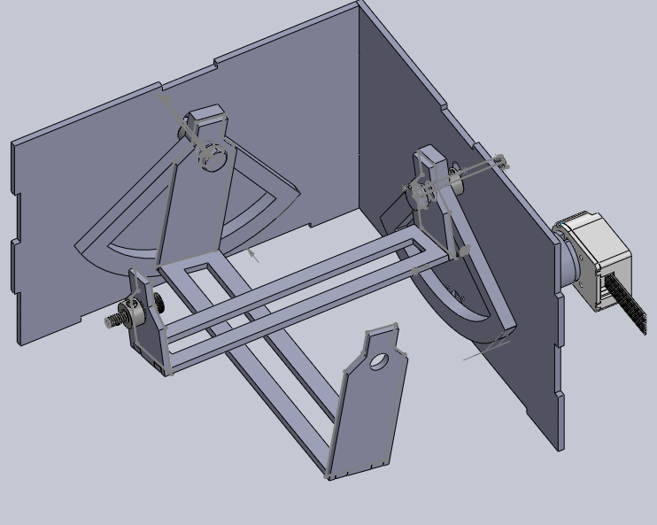
Solidworks model of joystick internals
For our device that would allow for both 2-DOF movement and force feedback, we designed a two-axis gimbal. We reused the transmission from the Hapkit (paddle and friction drive) to couple each axis with a motor. Motor positioning data was obtained with optical encoders in place of the Hapkit's MR sensors. The optical encoders are Maxon HEDS-5540 encoders, coupled with a 10-watt Maxon RE 25 motor (datasheet).
Besides four 1/4-20' fasteners, the smaller parts (fasteners, bearings, shaft collars, etc) used were taken from the Hapkit parts list or found in the CHARM lab. All other parts besides the paddle were modeled in Solidworks, then laser cut from either 1/8'' acrylic or Duron in the Product Realization Lab. Acrylic was used for the gimbal and duron for the joystick's container. The frame was initially assembled using epoxy, but following an unfortunate incident where gravity got the better of the structure, hot glue usurped the favored spot.
The joystick itself is a repurposed wooden chopstick (no longer sanitary) mounted to the top of the device with rubber bands and duct tape. The duct tape is flexible enough to allow the chopstick to move and rotate as a 2D pivot, while the rubber bands provide enough friction for the joystick to remain vertically anchored and consistently coupled with the gimbal.


!!! Electronics
The joystick was powered by an Arduino Uno and the Arduino Motor Shield. The Uno reads and processes the motor encoder values, while the shield's built-in motor controller allows it to drive the two motors via PWM.
In order to read both encoder values, each encoder had to communicate with the Arduino via a pin capable of performing software interrupts. The Arduino Uno only has two interrupt pins (2 and 3). Unfortunately, the Arduino Motor Shield is hard-wired to use pin 3 as Motor A's PWM input. This caused us a sufficient amount of trouble - we explored a number of options to resolve the issue, finally deciding on externally wiring the shield to the the Arduino instead of piggybacking the motor shield onto the board. Note that all the pins do not need to be connected from the shield to the Uno - only the pins specified below are necessary for function of both encoders and motors. A circuit diagram of the wiring we used is shown below:

With this configuration, the Uno writes to pins 5 and 6 as the two motor's PWM pins instead of the default 3 and 10, reserving pins 2 and 3 as interrupt pins for the encoders.
Software
A map can be read from a text file, with an arbitrary number of rows and columns. Each character represents a 40px by 40px tile. 'X' denotes a solid wall in that tile, and any other character denotes navigable space. A sample map:
---xxxxxxxxx----xxxxxxx-xx--xxxxxx-------xxxxx-xxx---xxxx--xxxx--xxx-xxxxxx-xxxxxxxxxx--The user's x, y position is initially set to (20, 20), in the middle of the first tile. The functionality we desired was for the physical position of the joystick to translate directly into the user's velocity. Since both axes of the joystick were coupled with the two motor shafts, reading the encoder values from both motors would allow us to determine the 2-axis displacement of the joystick.
To interface with the encoders, we use 3 C header files used in the ME327 Haptics class (TimerOne.h, PinChangeInt,h, and Encoder.h). Using these external libraries allows us to abstract away the process of parsing data from the digital encoders, giving us the angular displacement of both motor shafts in degrees. These raw encoder values easily translated into the joystick's physical displacement, which is then converted into x and y velocities. If no collisions occur, the virtual (x, y) position of the user change accordingly.
If there is a collision, instead of moving the user's (x, y) position, the motors are actuated with a force directly proportional to the joystick's displacement until the user is no longer moving in the direction of the wall. In other words, the faster the user is moving as he collides with a wall, the greater the opposing force output from the motor.

The graphical display of the maze, as generated by Processing.
Finally, for visual feedback (not necessary but used for the sake of debugging), we used Processing to generate a simple graphical display of the maze. Processing was able to receive information about the user's position using Serial communication through the USB connection between the computer running the Processing program and the Arduino board. Every "tick," the Arduino would write the user's (x,y) position to Serial, encoded in a single unsigned 32 bit integer.
Serial.println((int(xpos) << 16) + int(ypos));
The Processing program reads the second-to-most recent line (in case the Arduino was in the middle of writing a position when the program checked for Serial input), and decode the information in the corresponding number.
Functionality
The original purpose of our device was to allow a user to navigate through a 2-D environment/map while relying solely on haptic feedback. The positioning of the joystick controls the user's velocity in a virtual environment. When the user collides with a virtual wall, a force is actuated on the joystick proportional to the velocity at which the user is travelling, simulating a "crash." The device works as planned, though the "crashes" can be a little jarring, especially since the user has no sense of his speed or position until he hits a wall. Thus, the virtual environment feels very discrete, as if there exists only two states: wall and not wall. This makes activities like maze traversal more difficult than originally intended.
A potential improvement to the device could apply a small force to the paddle when a user gets close a the wall while travelling towards it, not just when a collision occurs. This way, the user is not forced to receive information solely by blindly crashing into walls, and instead has a sort of sixth that allows the avoidance of obstacles while still being provided information about them. The resulting environment would also feel more continuous and natural. Our maze-map is currently binary - every point is either wall or not-wall - a more nuanced map resulting in different haptic responses could further increase the utility of the device.
To improve the device's immersiveness, sound could be used as additional feedback to the user. Perhaps we could play a jarring sound when the user collides with a wall, or periodic "footstep" sounds whose frequency indicates the speed at which the user is travelling.
As mentioned in the introduction, the ultimate functionality of a haptic joystick can be maximized when it mirrors the real world - coupling haptic feedback with real-time virtual renderings of environments can create a compelling interface, especially for individuals with multi-modal navigational impairments.
Acknowledgments
Special thanks to Professor Allison Okamura for her help and constant patience in the face of our missed deadlines (we swear that Gantt chart was a joke), and so much love to her graduate students Tania, Nick and Sam - the project literally wouldn't have been possible without their wisdom and last-minute frantic debugging help.
Files
- Attach:joystick_display_processing_files.zip
- Attach:joystick_arduino_files.zip
- Attach:joystick_solidworks_files.zip
References
- http://electronics.howstuffworks.com/joystick8.htm
- http://charm.stanford.edu/ME327/JaredAndSam
- http://ieeexplore.ieee.org/xpl/articleDetails.jsp?tp&arnumber=1406999&queryText%3Dokamura+snaptic
- http://www.wseas.us/e-library/conferences/2005salzburg/papers/492-204.pdf