

Angelo Brian

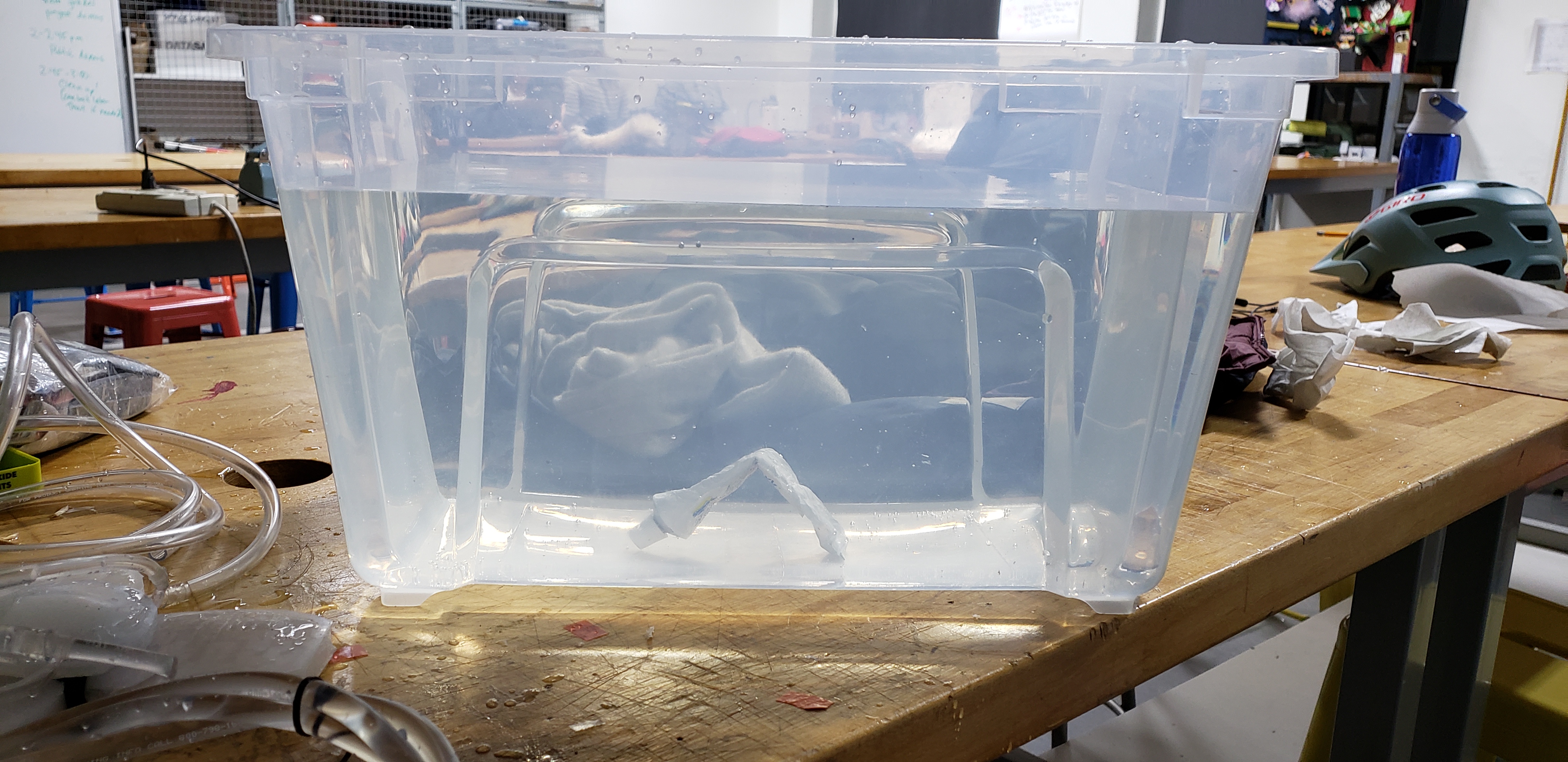
Initial pneumatic testing of gripper
Underwater Gripper
Project team members: Angelo Marquez-Nieto and Brian Delgado
Introduction
Our soft robot consists of a silicon gripper that utilizes both pneumatics and hydraulics to retrieve objects that are submerged in an aquatic environment. Our soft robot uses a good approach because the hydraulics allows it to sink underwater and the pneumatics allow it to come to the surface. Due to our choice of casting the gripper from silicon, it can grab a variety of objects no matter the shape nor size, as long as it is within reason.
Background
Our idea was heavily inspired by the week 5 lab that we did as a class, in which we made a silicon gripper that could be used on dry land. At the beginning we wanted to be a bit more ambitious with our projects, in the sense that we wanted to control not just the buoyancy but its direction as well. Our final design is heavily inspired by the aquatic animal, the jellyfish in both the aspects of look and originally in its movement. However, as we progressed through our research, we decided to focus on just the grasping aspect as opposed to the movement one, which resulted it in resembling more the look of an octopus than a jellyfish. One of the papers that we researched used several limbs to not only grab objects but to move as well (Arienti). Our design is similar in the sense that we decided to have each of the arms controlled separately as to have a greater control in its grasping ability overall. We did briefly look at a paper that focused around the movement of a robotic fish (since earlier we contemplated on adding movement) but really the only similarity between our final design and this is the use of pneumatics to cause movement (Marchese). We also looked at the website Soft Robotics Toolkit in which we found a variety of different gripper designs and bending arms. We decided to create a unique design instead however the utilizes tapered interior chambers instead.
Construction
First the CAD file that is in the files section should be 3D printed and a flat tray that is slightly bigger than the mold should be available (we used an old pizza box). About 150g of equal parts Ecoflex should be mixed and poured into the mold that was created by the 3D printer. Next, mix enough EcoFlex (equal parts) to fill the flat tray to a depth of about .5cm and leave to cure for about 4 hours along with the mold. Once they have both cured, carefully remove the cured silicon from the mold (it is quite susceptible to tearing due to the design of the mold) and remove the silicon from the tray as well. After both silicon pieces are successfully made, apply a generous amount of Sil-Poxy around all the edges of the silicon piece that was made in the mold (the side where the chambers are exposed). Make sure to also apply Sil-Poxy to the center and the tops of the flat surfaces of the inner chambers. Take the flat piece of silicon from earlier and place it on top of the other silicon piece and leave to dry for about 40 minutes. Once dried cut off the excess silicon and try to keep it as intact as possible as two circles with diameters of 5cm will need to be cut from it as well. Apply Sil-Poxy to the top edges of one of the circles, while being careful to not add any to the center, and afterwards place the other circle on top. While the adhesive dries for at least 40 minutes, make very small holes on the right side of each of the arms of the gripper near the base and insert about 8inches of 1/8 in. plastic tubing into each of the arms (3 in total). Apply a generous amount of Sil-Poxy to where the tube meets the body of the gripper and let it dry. Use the string to secure the tubes to the body of the gripper if needed, ex. leakage. Cut around 4 6ft (Or whatever length is desirable) of Ľ in. plastic tubing. Wrap double-sided tape around each of the ends of the tube (One tube should be left over) that were inserted into the gripper and connect the bigger tubing to the smaller one. Take the circular pieces that were glued together earlier and attach with Sil-Poxy to the center of the thinner side of the gripper. Create a small incision to the side of that piece and use Sil-Poxy to attach a 6 in long 1/8 in tubing into the incision. Use the remaining tube, repeat the previous step of attaching the smaller tube to the bigger one. Fill each arm with water. For actuation, connect the tubes leading to the arms to individual water pumps. Connect the top circular piece to an air pump. List of material used, and costs are located in files below.
Results
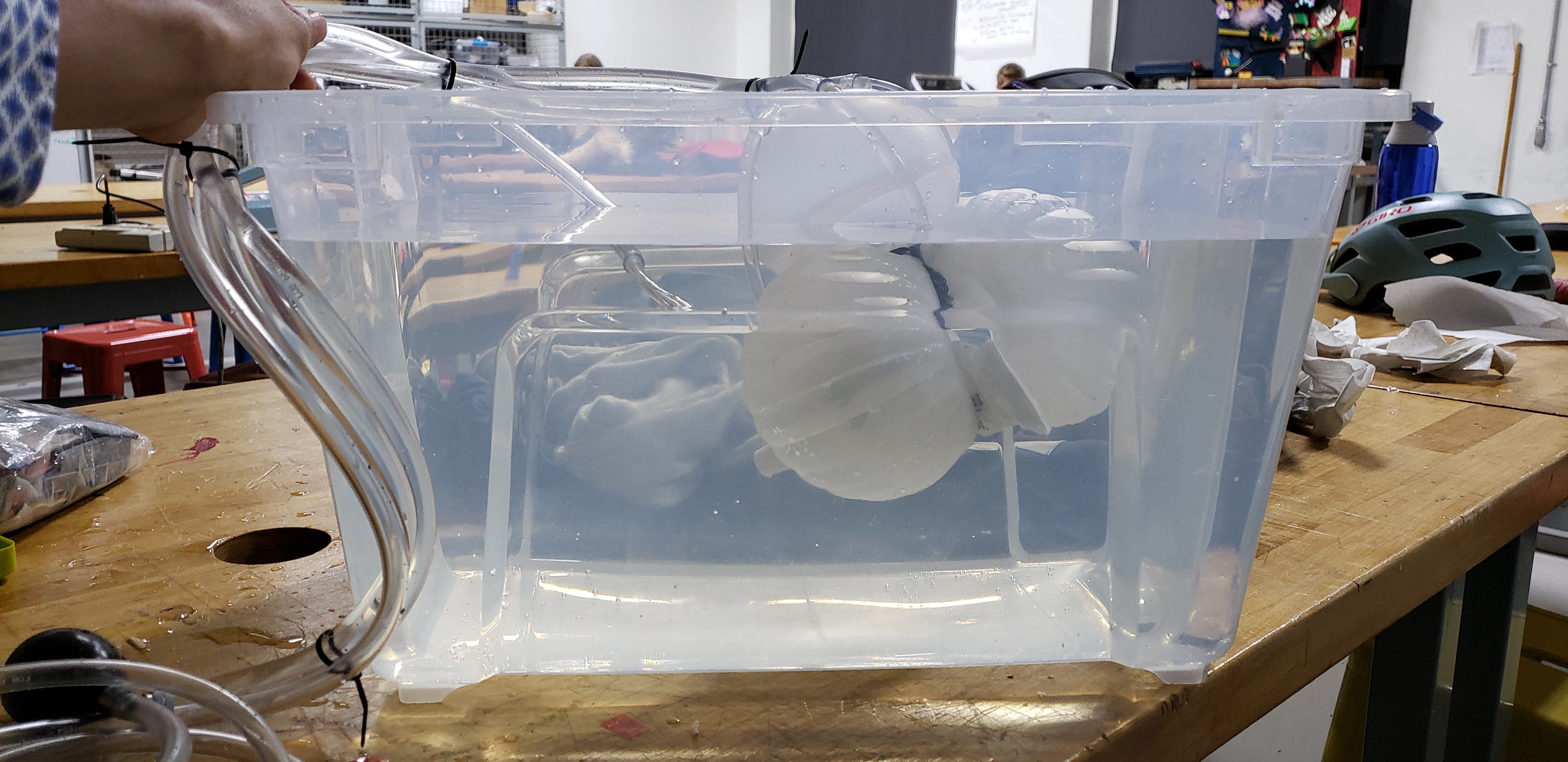
Prior to deployment, each of the gripper’s arms is filled with water so that when it is deployed into water, the combined buoyancy of the water and silicon that the gripper is made of will cause it to slowly sink until it lands atop its target. Once there, an offsite pump begins forcing water into each of the gripper’s arms. The arm’s interior chamber is designed in such a way that some areas, when they encounter interior pressure, will be less resistant to the interior pressure and will consequently “stretch” before other areas. This allows each arm to curl inwards as the interior pressure is increased when the water is forced into the gripper by the aforementioned pump. Each individual arm curling allows for the gripper to encapsulate its target and once encapsulated, the pneumatically actuated chamber inflates which upsets the existing buoyancy and consequently brings the gripper and its target to the surface.
As mentioned in the introduction, the gripper’s silicon components allows it to be flexible enough to be able to grab a variety of objects. When tested, this did turn out to be the case as the arms were able to successfully encapsulate and bring to surface all of the objects it was tested on (a half-empty tube of epoxy, a glass cup, and a water filled bottle), however more objects to test on would have allowed us to explore the grippers versatility to greater depths. An issue we ran into while testing was our robot’s deterioration through repeated use. Perhaps this was due to improper joining of components or simply stretching certain components of the gripper beyond their stretching capacity, but with that being said, future designs should ensure they have resistant components joined by robust connections. Setting all issues aside, the gripper can be used in a variety of situations where it may be too difficult for normal divers to reach certain places and at the same time is safer because it would not put a human at risk. It is safer because it would be autonomously controlled which eliminates the threat of drowning or other injuries. Its applications include but are not limited to search and rescue missions, payload deliverances, and exploration.
Acknowledgments
We would like to give special thanks to Professor Allison Mariko Okamura and Laura Helen Blumenschein, as well as all the teacher assistants in their assistance in creating this project.
Files
Stages of actuation:
Target is identified:
Gripper approaches target:

Target is encapsulated:

Gripper and Target are brought to the surface:
Video of Resiliency:
CAD File
Link to major components and their costs:
https://docs.google.com/document/d/1kXKf-PqBHVzcpeBvi6jAZ6WnWCUvRNmUwI7rU9YAocw/edit?usp=sharing
References
Arienti, Andrea, et al. “PoseiDRONE: Design of a Soft-Bodied ROV with Crawling, Swimming and Manipulation Ability.”
Marchese, Andrew D., et al. “Autonomous Soft Robotic Fish Capable of Escape Maneuvers Using Fluidic Elastomer Actuators.”
“Soft Robotics Toolkit.” Soft Robotics Toolkit, 1 Oct. 2017, softroboticstoolkit.com/home.
Checkpoint 1
Goals
Our first goal for this checkpoint was to create molds that will allow us to cast prototype gripper arms in order to determine what gripper design will work best underwater. Our second goal was to figure out how we will active the gripper while it is underwater.
Achievements
Gripper arms and molds:
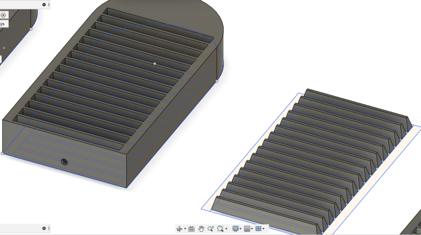
The arm pictured above has “fixed chambers” with interior walls of diminishing thicknesses. The hope is that the top portion will balloon out while the bottom portion will remain as it is allowing for the arm to curve down. Picture below is the mold that was created for this arm.


The arm pictured above has interweaving chambers and is based off a gripper used in a previous lab. The varying resistance caused by the chambers allows some areas to balloon out while others remain as they are allowing the arm to curve down. Pictured below is the mold that was created for this arm.

Initial brainstorming:
Pictured below is a visual example of our thought process
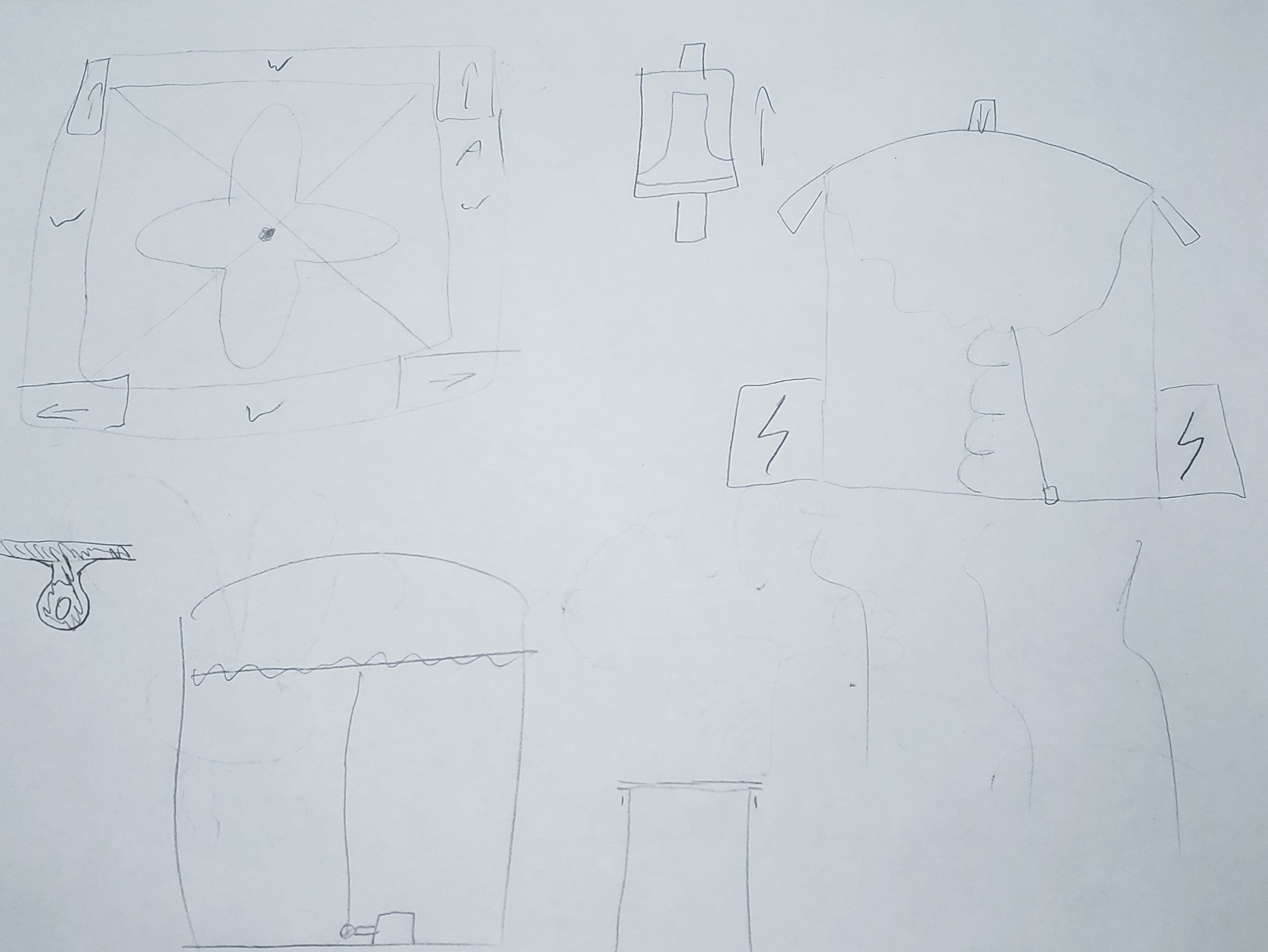
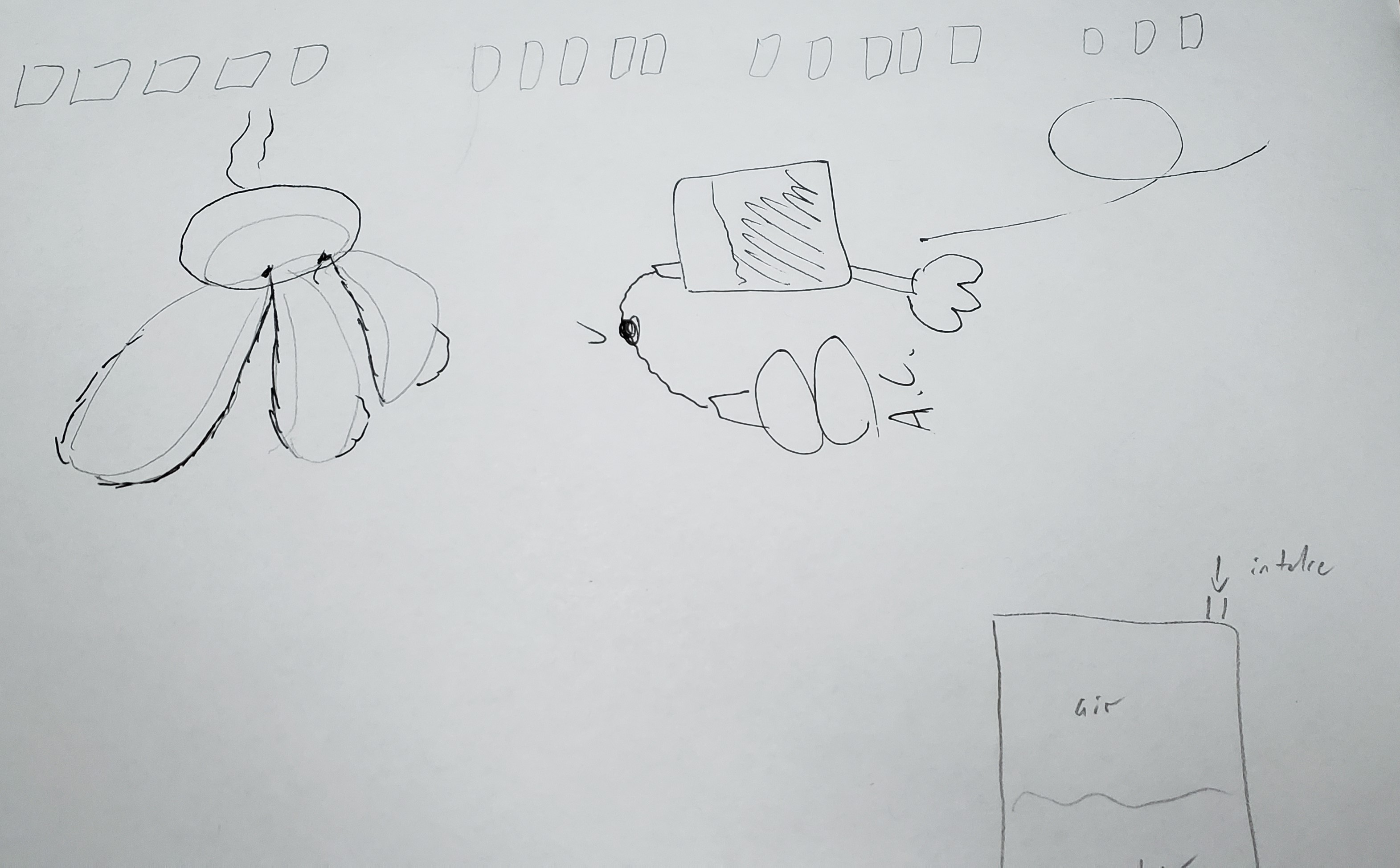
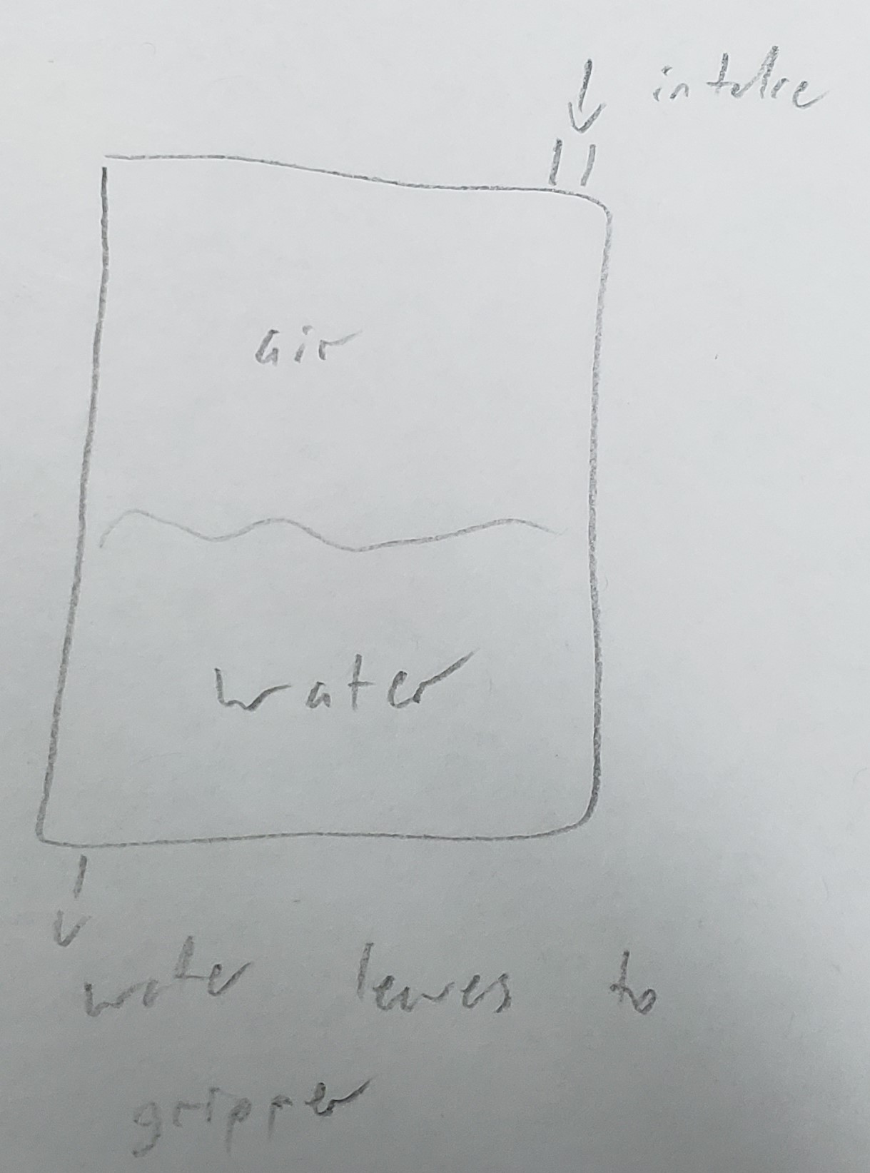
We will be using water to fill our gripper in the hopes that this partly solves the buoyancy problems that an air-filled gripper would cause underwater. After many designs, we settled on a closed compartment (pictured below) that will push water into the gripper as air pressure within the compartment increases.
Checkpoint 2
Our goal for this checkpoint was to have a working prototype. As of now, we've made prototypes for components of the prototype which showed our new interior inflation design to be successful, however, the full prototype is yet to be built. Due to our successful pre-prototype testing though, we are confident that our full prototype will too be successful.