Emma Tomas
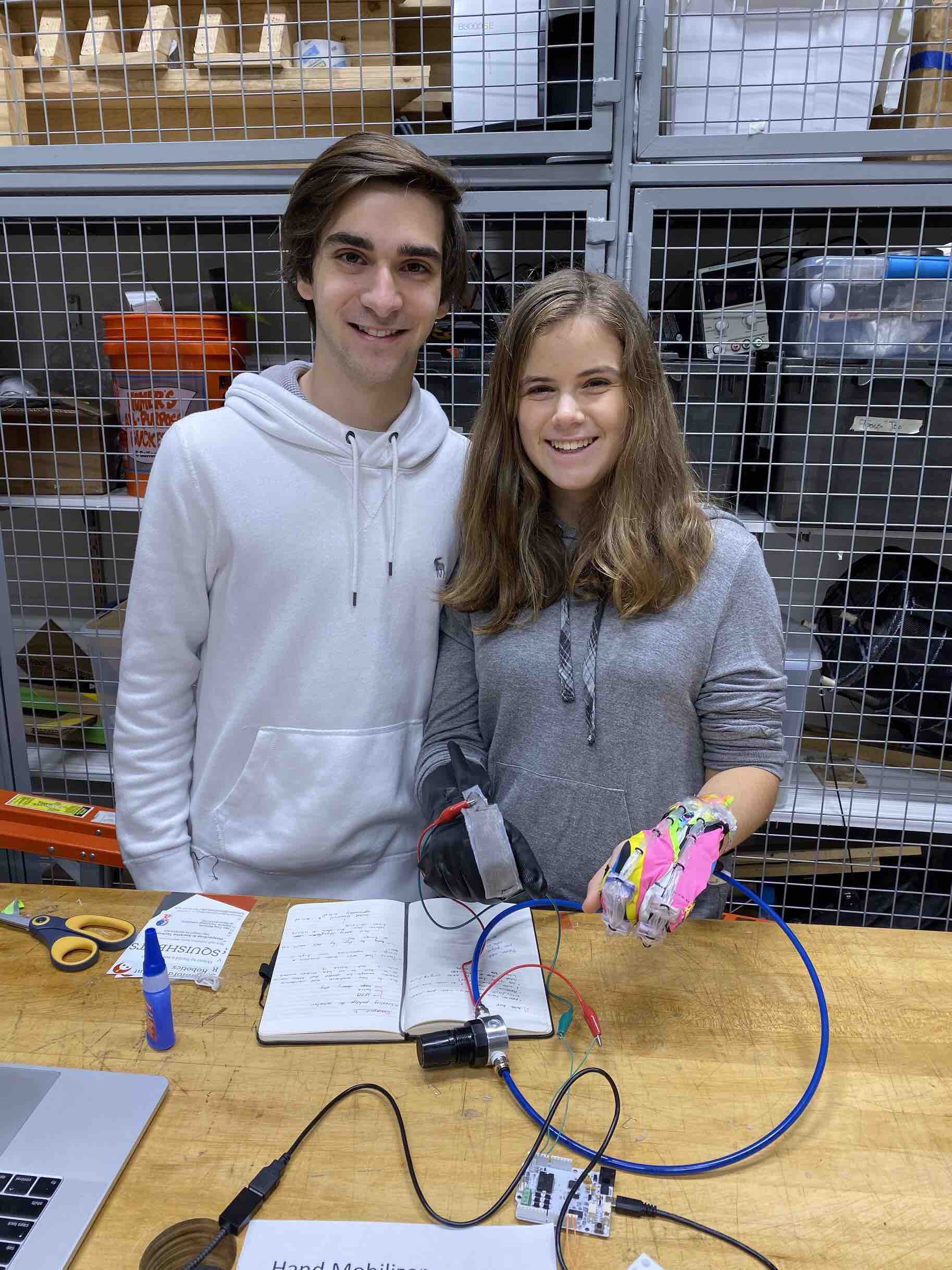
Tomas and Emma with
the Hand Mobilizer.
Hand Mobilizer
Project team member(s): Emma Passmore and Tomas Di Felice
Summary
Our soft robot is a hand mobilizer designed to assist patients who suffer from hand spasticity and fist clenching. It uses a soft-sensor on one hand to indicate with an LED when the patient bends their fingers, and a sPAM actuated glove on the other hand which helps open the patient’s hand when the LED is turned on. In the end, the glove achieved its main purpose. The sensor, turned the LED on consistently when the user bent their finger and the actuated glove successfully helped open the user’s hand. Improvements for the soft robot mainly include connecting and automating the opening of the air valve. The LED served as a good indicator, but in the future, a digital pressure valve would be added to the circuit. Thicker tubing for the sPAM actuators would help with the robustness and effectiveness as greater air-pressure would apply more force on the fingers.
Introduction
For this project, we wanted to help stroke patients suffering from spasticity. After a stroke, patients’ muscles usually become stiff and tighten and one of the major side effects is what is known as fist clenching. When attempting to recover and improve this condition, patients spend weeks next to physical therapists who open and close the patient's hands over and over again. Our intention was to automate and replace the repetitive movement performed by the doctors, create a soft robot device that can help the patient open and close their hands to regain mobility. Our approach serves our purpose the best because pneumatics and fabric gloves are durable and lightweight yet powerful enough to open a user’s hand. The use of two-way stretch fabric enables easy donning and doffing while allowing it to be comfortable as a wearable device. The addition of the foam block beneath the sPAM allows us to maximize force without adding heavy motors or equipment needed for other types of actuators. Additionally, the approach uses relatively inexpensive materials, making the device more accessible.
Background
Our project involves two separate main components: the hand extensions glove and the soft sensor glove. For the extension component, we decided to use a series of pneumatic artificial muscles (sPAM) actuators like those designed in Lab 2. In the paper “Design of a Soft Robotic Glove for Hand Rehabilitation of Stroke Patients with Clenched Fist Deformity using Inflatable Plastic Actuators”[1], researchers utilized plastic actuation tubes to open the hand of the patient. They describe that: “Upon pressurization, the actuators inflate, stiffen, and extend the fingers. The actuators were embedded in the finger pockets of a glove.”[1]
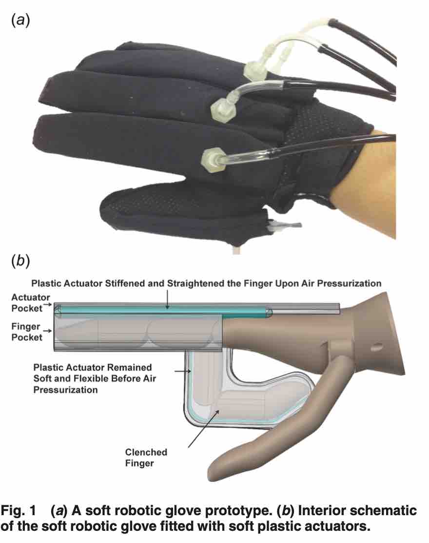
When designing a soft robot to extend a patient's hand, it is important to also consider the structure of the human hand, and how a wearable glove would interact with it in the best way possible. In “Moving toward Soft Robotics: A Decade Review of the Design of Hand Exoskeletons”[2], researchers mention that “with the rise of soft robotics, there has been a progressive shift from the conventional rigid mechanical structure designs to designs with softer actuation and designs that closely resemble the natural finger musculoskeletal structure”[2]. In this way sPAM actuators, with the separated artificial muscles, provide a structure that resembles the joints of a hand.
 [2]
[2]For the soft sensor, we decided to use a silicon-fabric stretchable capacitor which is “well suited for unobtrusive wearable body motion capture”. In the paper “A numerical method for measuring capacitive soft sensors through one channel”[3] researchers explain that this type of sensor is especially valuable as they can be used in “in situ”, without the need for cameras or large equipment, making it the perfect fit for our wearable soft robot.
Construction
Our project involves constructing two separate components: the actuation glove and the sensor glove.
Materials Cost:
For Both Gloves
- Thread (1 spool) - $0.46
- Clear Tape (1 roll) - $2.13
- Purple Foam Board (5 cm2) - $0.06
- Hot Glue Stick (1) - $0.18
- Velcro (1 roll) - $3.76
For Extension Glove
- Two Way Stretch Fabric - (35 x 10 cm2) - $0.17
- Thin Plastic Tubing (61 cm) -
- Air Tube (6’’ of .25” tubing) - $1.85
- O-Rings (18 rings) - $1.05
- Super Glue - $2.83
- Double-Sided Tape - $10.05
For Sensor Glove
- Kitchen Glove (1) - $3.00
- Arduino Board (1) - $10.00
- Breadboard Jumper Wires (4) - $0.08
- Resistor (1) - $0.10
- Alligator Clips (2) - $4.99
- Bred Board (1) - $3.97
- Conductive Knit Fabric (2 x 5 cm2) - $2.45
- EcoFlex 00-30 Part A and Part B (20 g) - $0.44
- Cardboard (10 cm2) - $0.10
Constructing Extension Glove:
Trace the outline of your pinky and ring fingers and an additional foot long strip onto a sheet of paper to form a template. Use this template to cut out two strips one that only includes the hand and one that includes the hand and the rectangular strip. Sew these two pieces together with the dull sides facing outwards. Repeat this process for the middle and index fingers.
Now, cut 6 1cmx1cmx2cm rectangular prisms out of the purple foam board. Don the finger gloves and mark the center between your two knuckles on the glove. Use hot-glue to attach the foam prisms to the finger glove at the marked places.
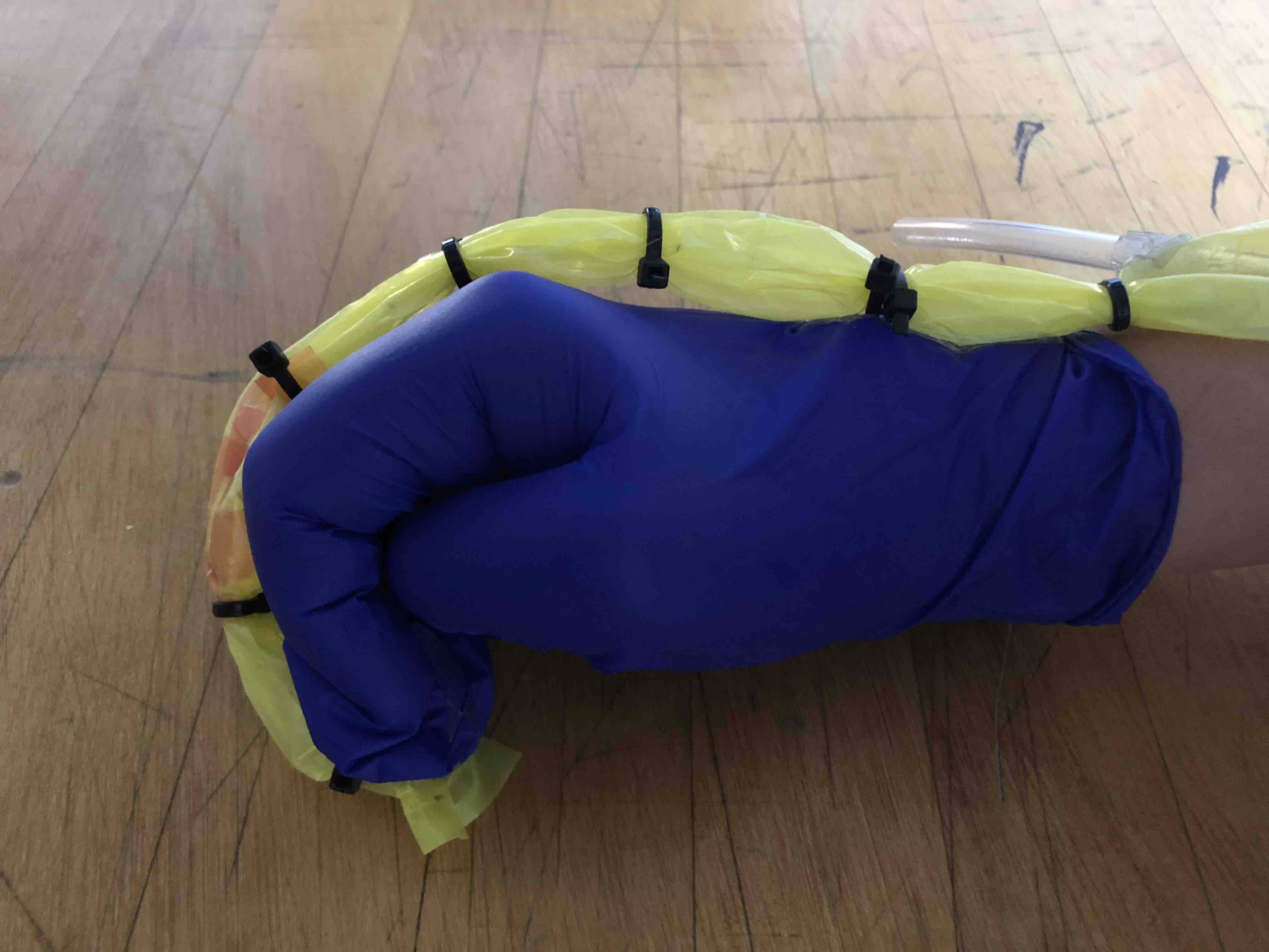
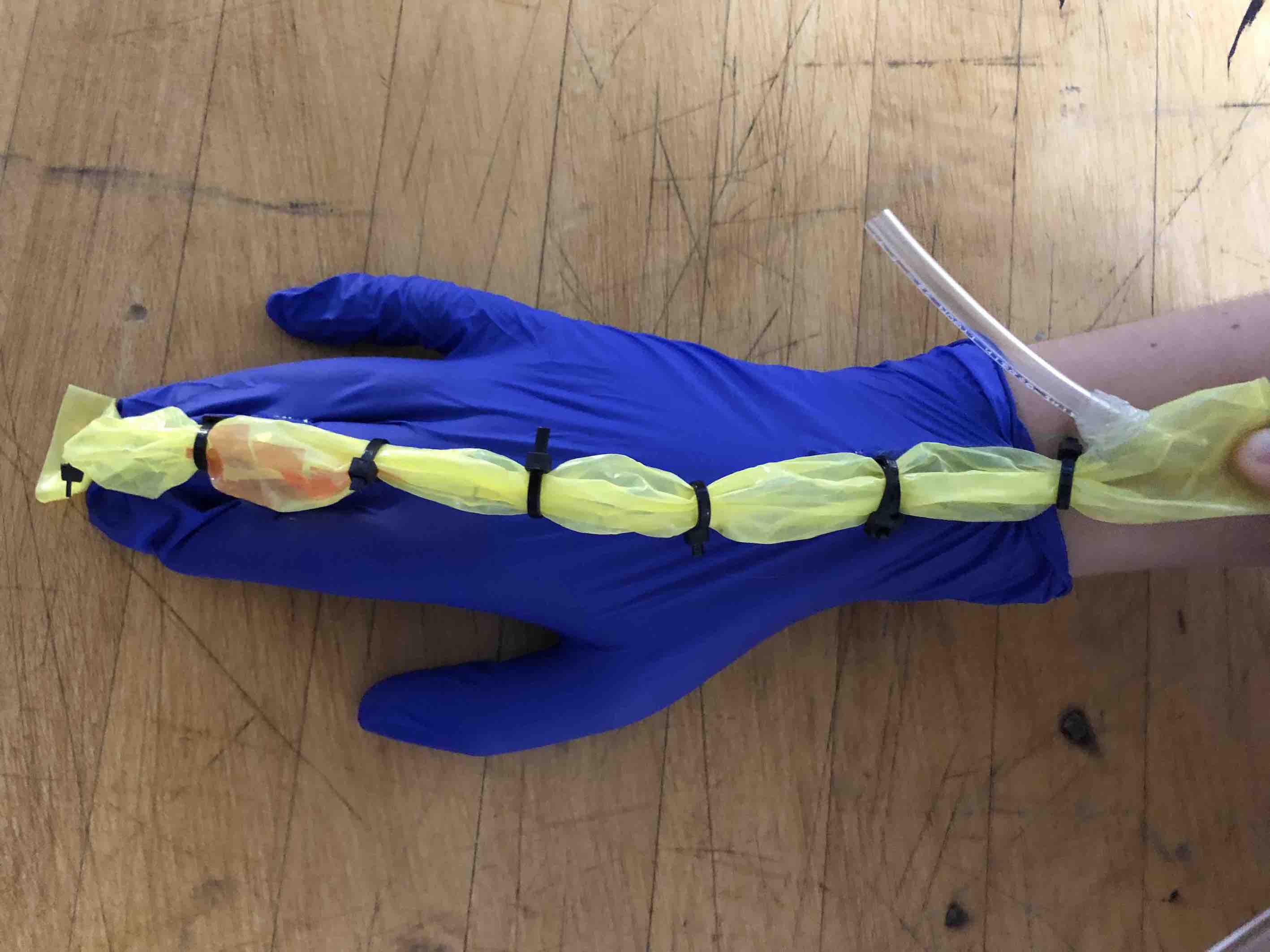
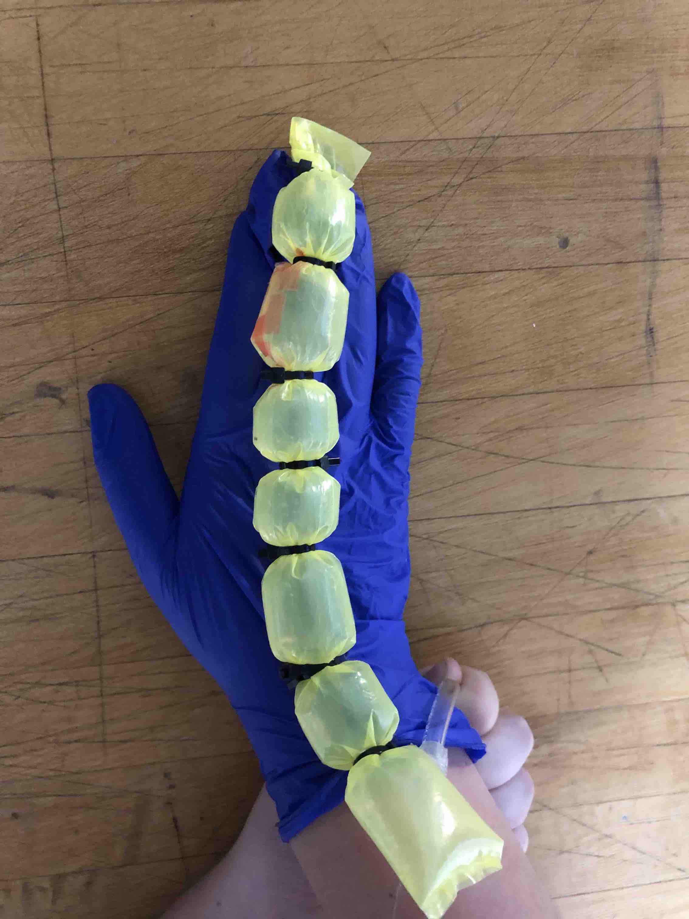
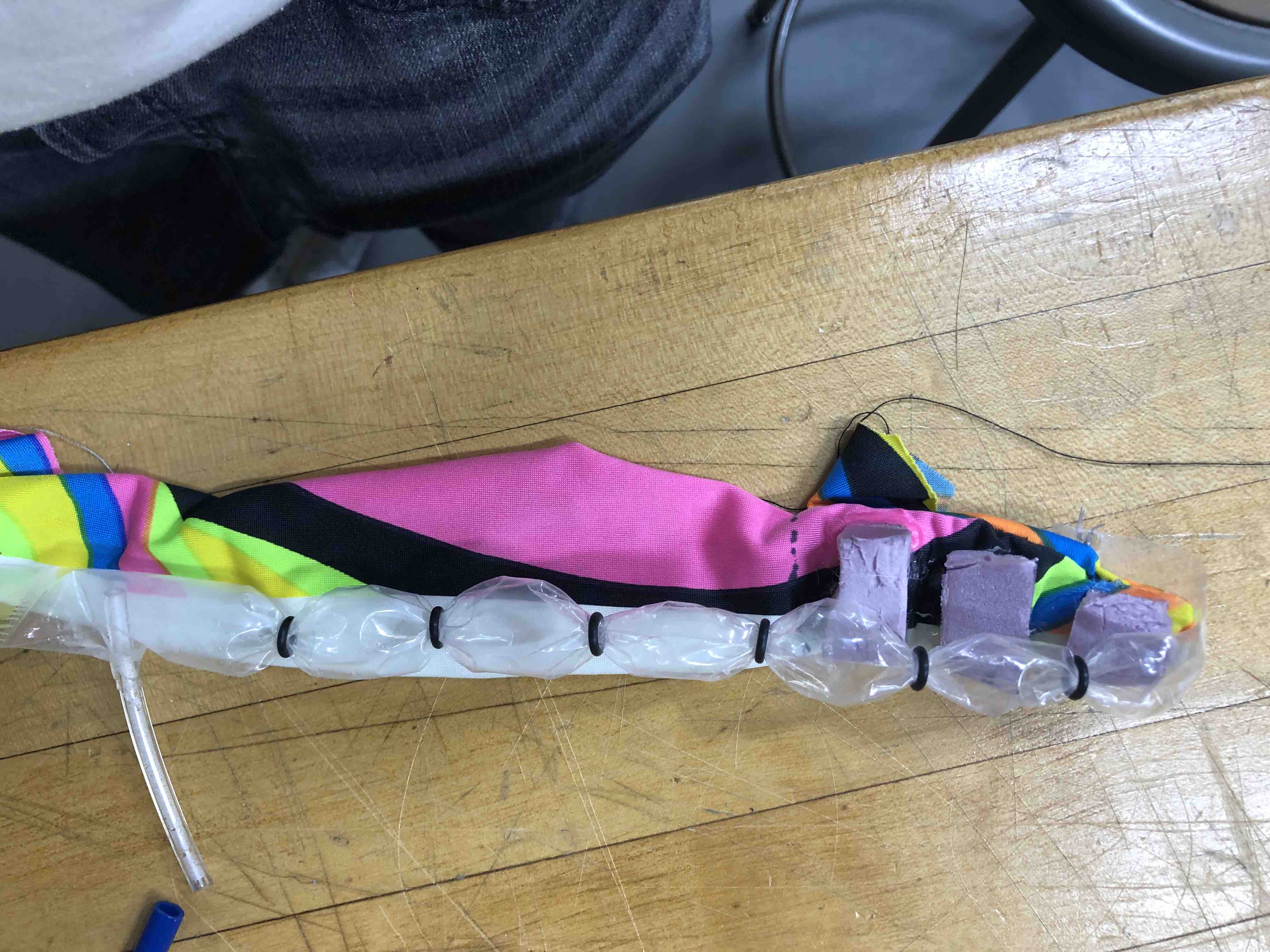
Next, construct two SPAM actuators. Cut out a 30cm piece of thin plastic tubing. Heat seal one end of the tubing 2 cm from the end of the tube. Thread 6 o-rings onto the tubing for the pinky and ring finger, and 7 for the other tubing. Insert an air tube. To do this, wrap the double-sided tape around the base of a 6 cm air tube. Then, poke the tube through a small hole 3cm from the end of the unsealed side of the tube (from the inside). Stick the tubing to the double-sided tape on the air tube to seal the tube. Seal the end of the tubing close to the air tube. Repeat this process on the second tube.
Then, attach the SPAM to the glove. First, sew the end of the non-air tube to the underside of the finger glove about 2cm from the tip of the glove. Second, line up the first three o-rings with the purple foam prisms. Sew threw the foam block and over the tube to the front and back of the o-rings to secure them to the foam blocks.

Third, sew the fifth o-ring to the two-way stretch fabric. To make sure that you sew the o-ring to the correct place, don the finger glove, straighten your fingers, and lightly pull on the glove and SPAM. Mark where the fifth o-ring touches the fabric. Sew the o-ring to this marked position. Fourth, sew the air-tube end of the tube to the fabric. Again, don the finger glove, straighten your fingers, and lightly pull on the glove and SPAM. Mark where the end of the SPAM touches the fabric and sew the end of the tube onto the fabric at this point. Repeat these steps to attach the SPAM to the second finger glove.
Once both finger gloves are individually assembled, join them together. Sew the edges of the glove measure and mark the edge sew the edge of the pinky/ring finger glove and its fourth o-ring to the edge of the index/middle finger glove.
Finally, attach the velcro straps. Don both parts of the glove. Straighten your fingers and pull the ends of the fabric taught. (Since the SPAMs are attached to the fabric they will both be taught as well.) Ensure that the wearer feels equal tension in both the pinky/ring finger glove and the index/middle finger glove. Have your partner wrap a piece of velcro around the ends of the fabric. Mark where the velcro touches the fabric. Sew the velcro onto both strips of the fabric where marked.

Constructing the Sensor:
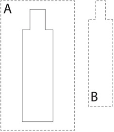
[SCALE the image so that the sensor is about 2cm wide] [4]
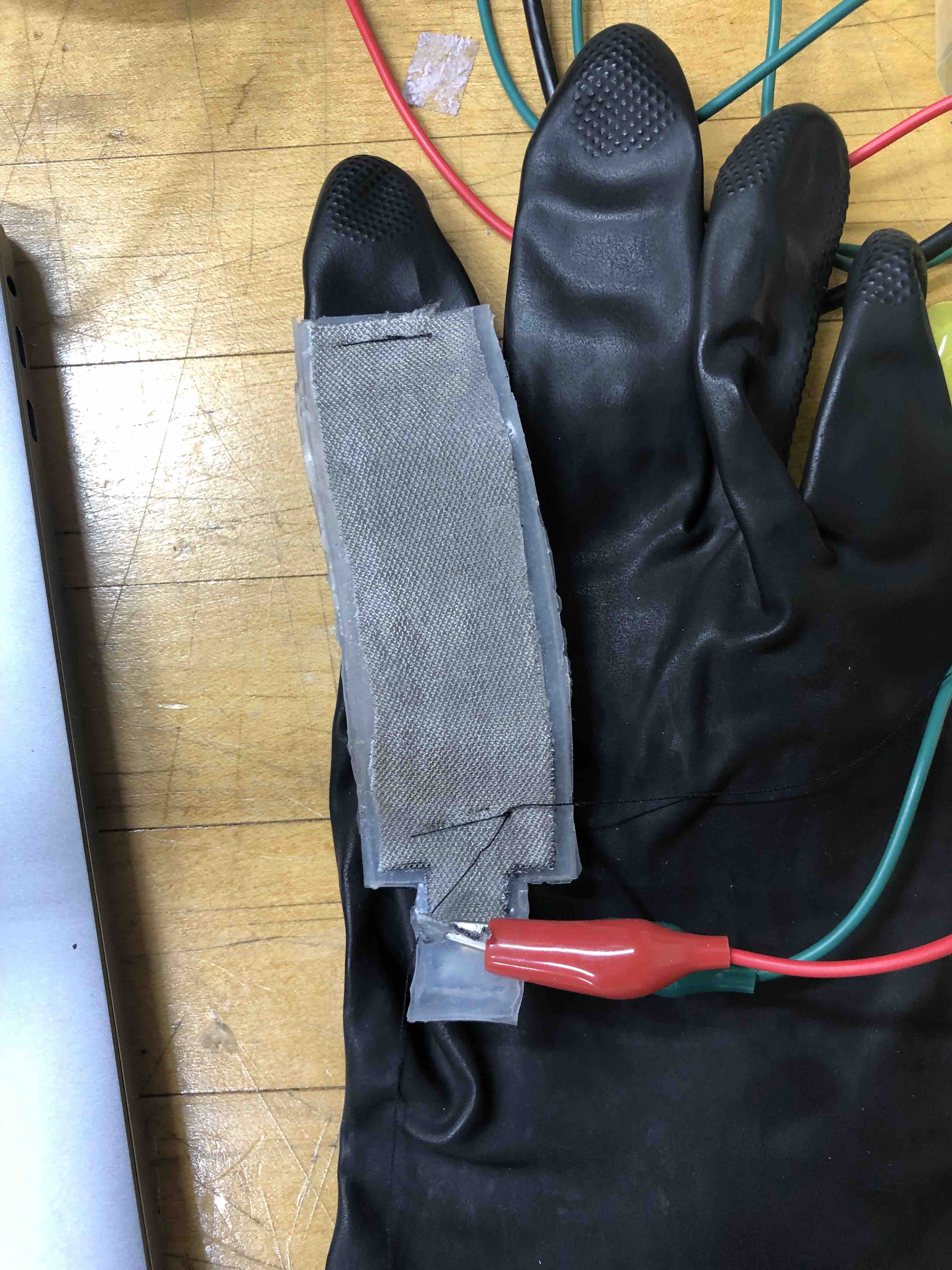
Cut along the lines to cut out the templates A and B. Trace the exterior perimeter of A onto the cardboard and cut out the traced rectangle. Laminate templates A and B and the cardboard with clear tape. Trace template B onto the conductive fabric twice to create two fabric electrodes. Mix 10g of EcoFlex 00-30 Part A and 10g of EcoFlex 00-30 Part B together. Stir well and gently tap the mixture/let it sit until the small air bubbles are gone. Place template A on top of the laminated cardboard to create a shallow mold. Pour a thin layer of silicon into the mold and smooth it out. Let the silicone cure. Use a very thin layer of silicon to attach the fabric electrodes to each side of the silicone strip. Make sure that you do not attach the fabric to the tip of the silicon strip.

(Credits to Soft Robotics Toolkit: See References)[4]
Constructing the Sensor Glove:
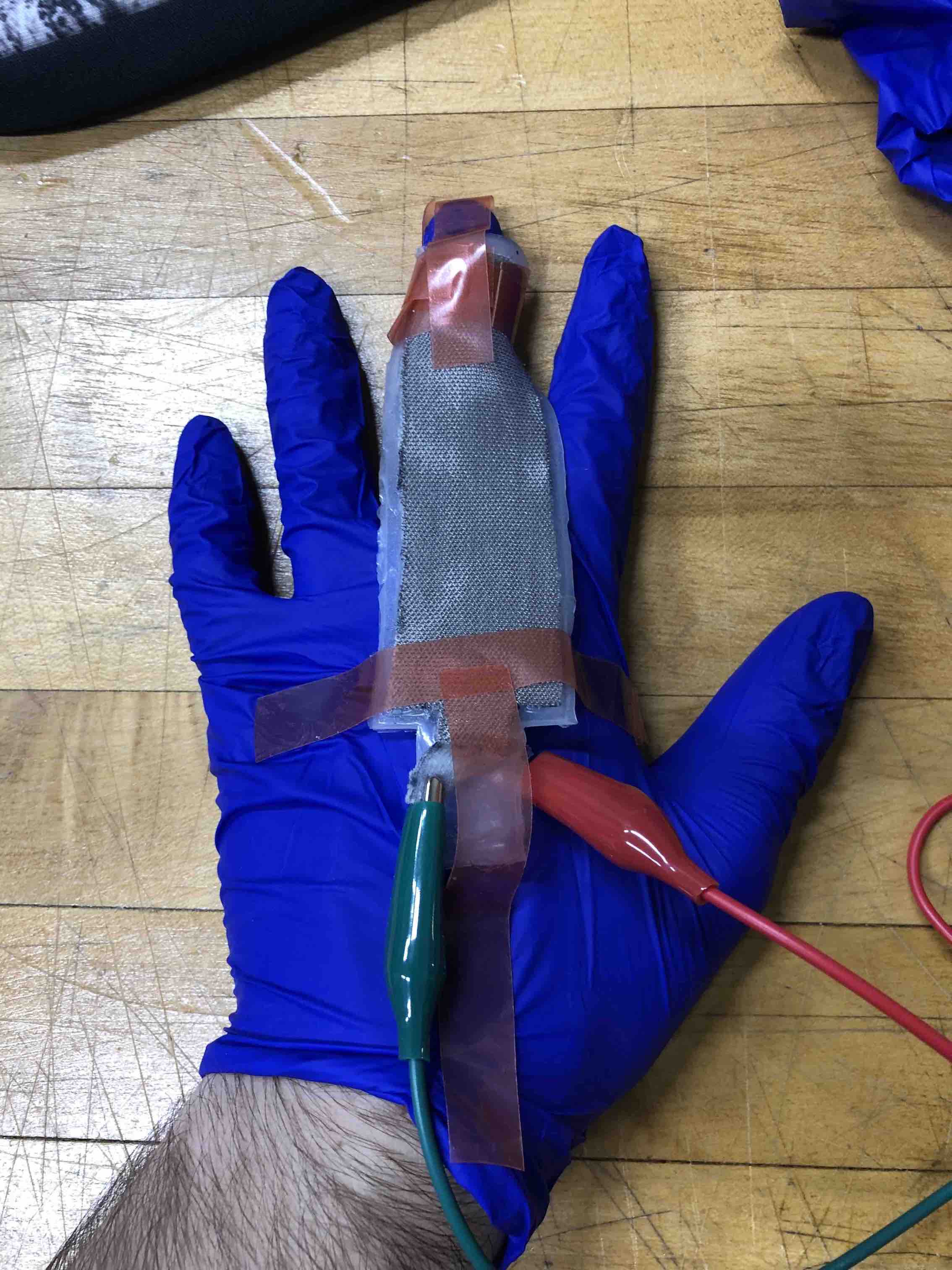
First, attach the Sensor. Cut out two 1cmx1cmx2cm pieces of purple foam. Use hot-glue to glue them to the index finger of the kitchen glove about 3 cm a ⅔ the way down the finger. Now, don the glove and straighten your index finger. Center the sensor over two pieces of purple foam and mark where the ends of the sensor touch the glove. Sew the ends of the sensor to the glove (the side of the sensor that attaches to the alligator clips should point towards the arm).
Second, integrate the velcro strap adjustment into the glove. Cut two slits in the glove on either side of the wrist. Thread a piece of velcro through these holes. The velcro should not be visible except for at the top of the wrist. Attach the ends of two alligator clips onto the loose portion of the fabric, one clip on each side.

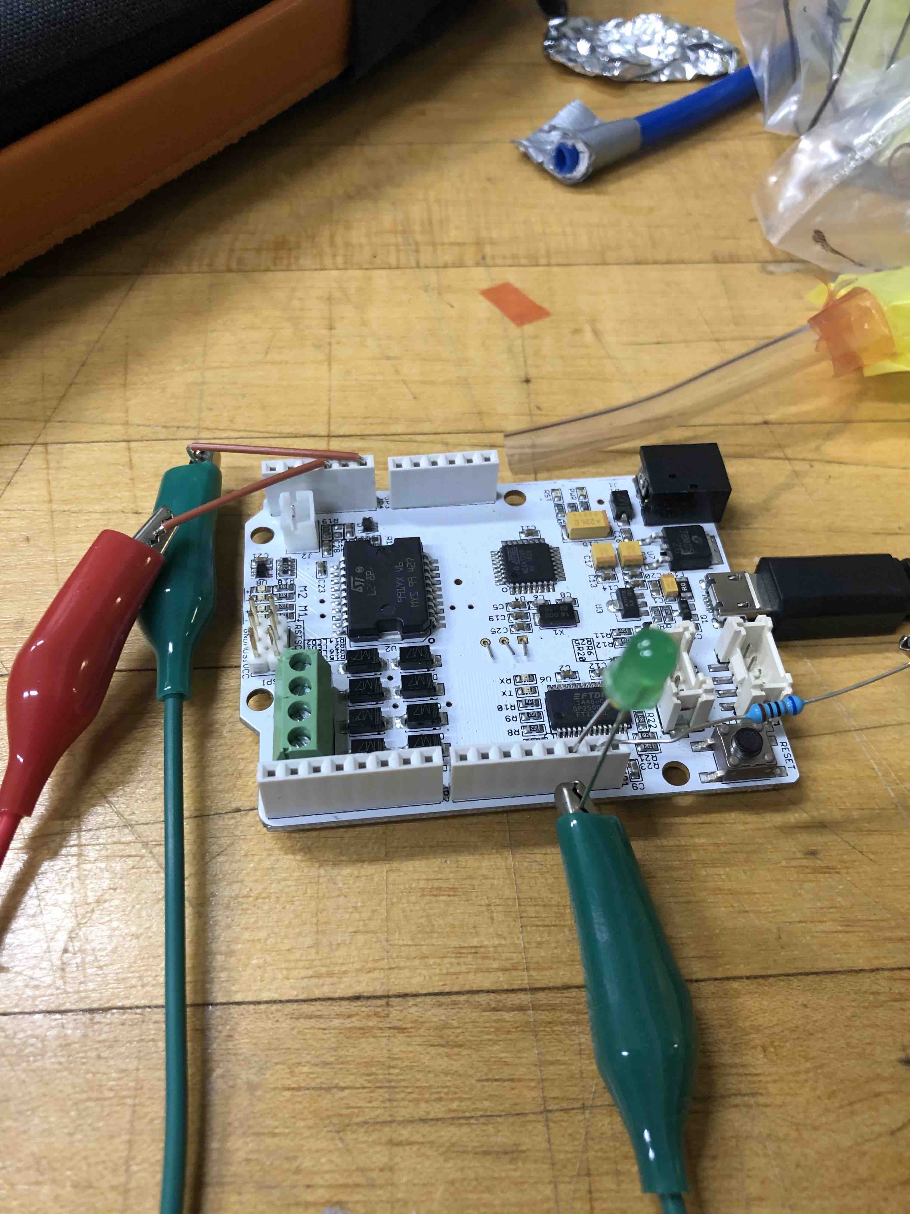
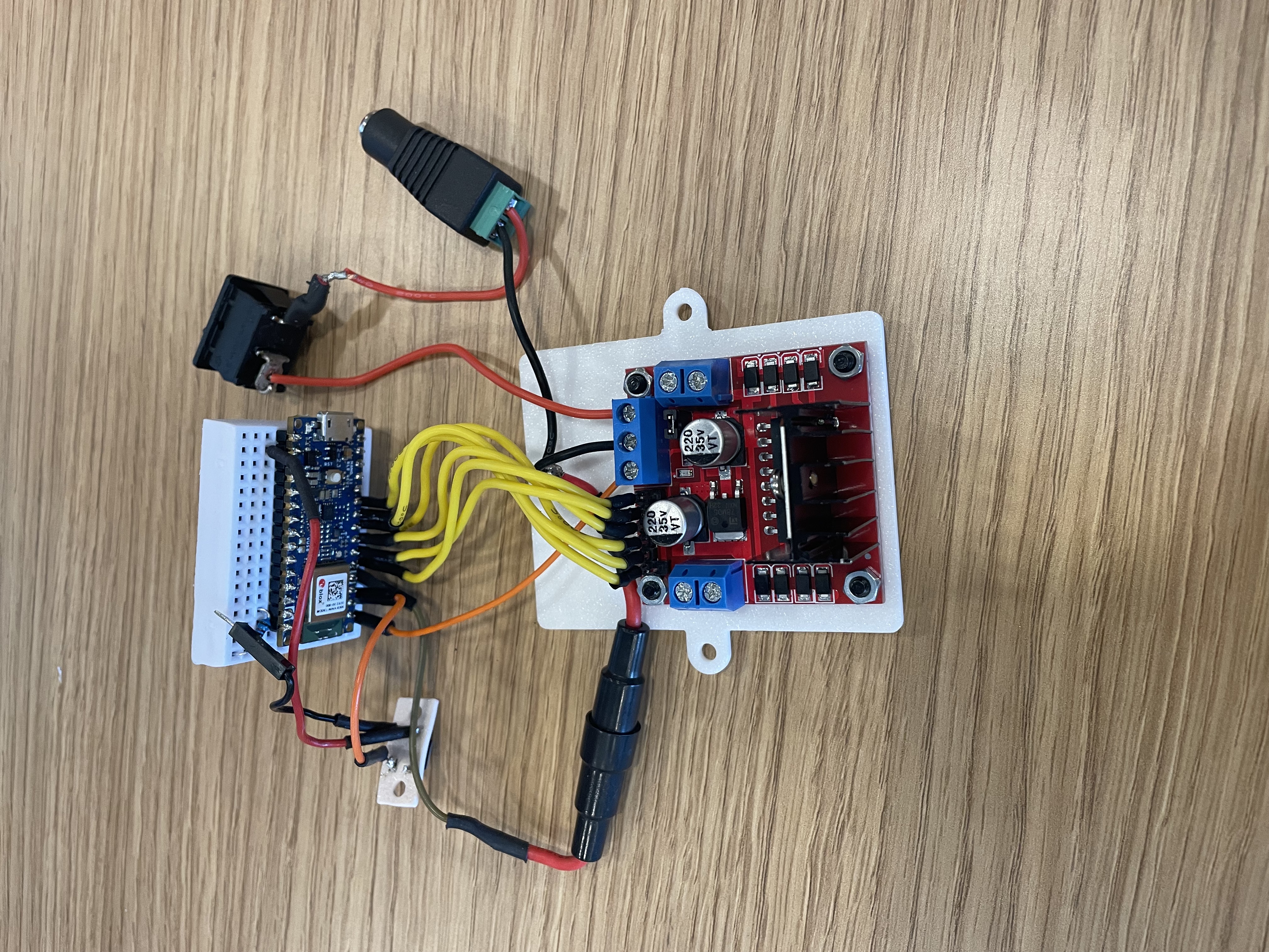
Put jumper wires in pins A0 and A2 and attach the other side of the alligator clips to each jumper wire. Using a breadboard, create a circuit where the long leg of the LED is connected to pin D13. Add a resistor and connect it to ground of the Arduino board with jumper wires.
Coding the Sensor Glove:
The code for the capacitance sensor is based heavily on the code given for Lab 6. This code used the input pins of the haptic board to calculate the capacitance. In order to turn on the led after a threshold capacitance was reached, we had to make some slight modifications. First, remove references and calculations including the length of the sensor and slope, as our project does not involve knowing the length of the sensor. The code is attached in Files. Add code to set up LED with output pin D13. Add code for determining the initial rest capacitance of the user. Finally, using the initial capacitance, set the threshold as initial + 0.5, the point at which LED turns on, else turn LED off. (See code for reference)
Results
Our soft robot had two components: a soft senor glove and a mobilizing glove.
The soft sensor integrated into the soft-sensor glove measured a change in capacitance. It is essentially a capacitor composed of a silicone dielectric placed in between two strips of conductive fabric. The sensor’s capacitance (C) is a function of the area of the plates (A), the thickness of the dielectric (d), and a property called the permittivity of the dielectric (e): C = EA/d. Because of how the sensor is attached to the glove when the user bends their finger, the sensor stretches. This stretch causes the surface area of the conductive fabric to increase, causing an increase in capacitance. The Arduino program measures this increase. To maximize this change in capacitance, we added foam pieces between the sensor and the glove. Consequently, when the finger bent, the conductive fabric stretched farther.
In order to calibrate the soft sensor glove to each user, our code recorded an initial resting capacitance for each user. Then, it calculated the appropriate capacitance threshold so that, when each user bent their finger, the consequent measured capacitance change would signal for the LED to turn on. To test our design, we opened and closed our hands ten times until the LED consistently turned on. We defined "consistent" as the LED illuminating 20 times in a row. Our mobilizing glove uses sPAM actuators to contract and open the user's hand. sPAMS are a class of actuator that uses air pressure to imitate the function of biological muscles. When air is pumped into the plastic tubing, the O-Rings prevent outward expansion at regular intervals. As a result, the tubing forms conical esque shapes as shown in the diagram. By the triangle inequality, the slant height of these cones is longer than their height. Since the tubing material is inelastic when inflated the tubes expand radially but contract axially.
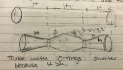
“Biologic muscle acts by contracting to produce force and movement. Muscles also often work in pairs since each muscle can only cause force in the contraction direction. These pairs are called antagonistic since they are arranged to “fight” each other. Pneumatic artificial muscles share these properties, acting in antagonistic contracting pairs or groups.” [5] Because the sPAM is attached to the glove and secured to the forearm, when the sPAM contracts, the hand is opened. The glove is constructed from a 2-way stretch fabric. Thus, it cannot stretch in the direction that the sPAM contracts. Consequently, the contraction force that the sPAM exerts is maximized. The foam pieces between the actuator and the glove increase the lever arm so that the torque on the fingers’ joints is sufficient to extend them. We also placed the foam prisms approximately in between each joint and then secured the O-Ring to these pieces in order to maximize the contraction of the pneumatic muscle between each of the finger joints.
With regard to our humanitarian goal, in the future, we could connect the actuator and soft sensor. This change would remove the need for a person to open the pressure valve when the LED illuminates. To accomplish this objective, a digitally controlled pressure valve would need to be added to the circuit. Similar to the LED prototype, when the finger is bent and the threshold capacitance is reached, the Arduino board would send an electric signal to the pressure valve. The pressure valve would open, inflating the sPAM. When the finger is straightened, the Arduino turns off the signal and the valve closes, allowing the sPAM to deflate and the fist to clench. We could not accomplish this due to the high cost of the equipment needed. Nevertheless, the LED serves as a great way of demonstrating how the soft sensor and sPAMs could be integrated in the future.
In terms of the application to our humanitarian aspect, our design serves as a useful proof of concept. When evaluating how valuable our robot would be for a stroke patient, the patient’s needs and abilities would have to satisfy possibly unrealistic requirements. For example, the patient would have to be able to slightly open their hand in order to don the glove. Additionally, although we managed to open our moderately clenched hands, some patients may be clenching very hard. Therefore, the force necessary to open their hands would require enough pressure to pop the plastic tubing. This limitation could be remedied by using stronger tubing. Another limitation was that the wrist of the patient hand to be kept straight for the actuation to function properly. A way of ensuring this in a future model could be to add a small brace that straightens the wrist. Moreover, despite these limitations, our current model satisfies our initial use case: automating the repetitive task of rehabilitation for patients who can slightly open their hands. The glove would effectively help these patients regain mobility. Similar to the actuator glove, the sensor glove serves as proof of concept. It is limited because, if the patient might have has two hands clenched hands, they could not use the sensor glove. However, since the sensor only needs to measure a change in length, it could be positioned on any other joints such as the elbow. Additionally, an ideal concept of the soft robot could also use one spam for each finger, maximizing the force.
Here are two videos of our robot in action!
Acknowledgments
We would like to thank Allison, Laura, Tita, and Ari for guiding and supporting us throughout the planning and construction of our project, helping us overcome obstacles and find the best materials.
Files
- Major Components and Approximate Costs: Attach:costs.pdf
- Arduino Code: Attach:code
References
[1] Yap, Hong Kai & Lim, Jeong & Goh, James & Yeow, Raye Chen-Hua. (2016). Design of a Soft Robotic Glove for Hand Rehabilitation of Stroke Patients with Clenched Fist Deformity using Inflatable Plastic Actuators. Journal of Medical Devices. 10. 10.1115/1.4033035.
[2] Shahid, Talha & Gouwanda, Darwin & Nurzaman, Surya & Gopalai, Alpha. (2018). Moving toward Soft Robotics: A Decade Review of the Design of Hand Exoskeletons. Biomimetics. 3. 10.3390/biomimetics3030017.
[3] T. Andreas, I. A. Anderson, "A numerical method for measuring capacitive soft sensors through one channel", Smart Materials and Structures, vol. 27, no. 3, pp. 035016, 2018.
[4] Soft Robotics Toolkit: https://softroboticstoolkit.com/resources-for-educators/tsh-sensor'
[5] Lab 3: Pneumatic Artificial Muscled: adapted from UC Santa Barbara course ME 125EH with the help of Prof. Elliot Hawkes
Checkpoint 1
For our first checkpoint, we wanted to create a prototype for an actuator that would open the user’s hand. We wanted to test the functionality and strength of glove on ourselves. The glove should be able to open our hand when slightly clenched. The glove should be easy to don and doff. Additionally, we wanted to test that the soft sensor measures a change in capacitance when the trigger finger is bent.
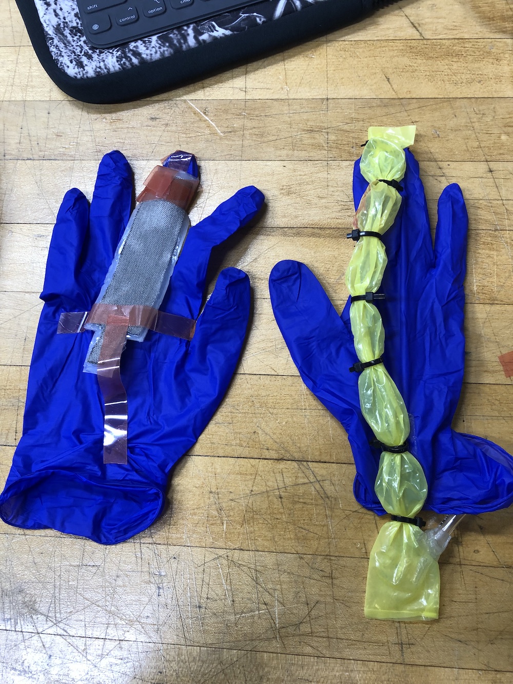
We attached a SPAM actuator to a latex glove. We managed to make the user's hand open slightly when we actuated the SPAM. We tried attaching the SPAM in different ways to maximize the force exerted on the hand. We found that it worked best when the SPAM was attached to the wrist, in between the second and third finger joints and at the tip of the finger. For the soft sensor, we checked that when it is attached to a finger that bends, a big enough change in capacitance is measured (So that we can actually see that the change is caused by a finger bending and not a slight movement of the hand) We recorded a change in capacitance from approximately 15 when unbent, to 25 when bent.
Improvements for next checkpoint:
Although we managed to slightly open the hand, we noticed that the force wasn’t strong enough to open a tightly clenched hand. To solve this, we thought of adding two SPAMS, having each one work on only two fingers instead of the whole hand. We also wanted to make the SPAM smaller so it doesn’t interfere with the user’s hand use. We also want to test attaching the SPAM with different materials so that when it contracts it doesn’t detach from the glove.
Checkpoint 2
- Finalize the design for the SPAM actuated glove and the sensor
- Create a prototype for connecting the actuator and sensor
- Maximize the force that the SPAM exerts to open the hand
- Decrease the bulkiness of the glove and SPAM
- Improve ease and robustness when don and doffing
- Strengthen the connection between the spam SPAM and glove and Sensor and glove
We developed a stronger actuator. To increase the force exerted on the hand, we added pieces of foam in between the SPAM and the hand. Consequently, the distance that the SPAM stretched when the hand was clenched increased. Consequently, when the [lever-arm] is longer so when the SPAM contracts it exerts more opening force on the hand. Additionally, we attached two actuators to the hand one to the index and middle fingers and one to the ring finger and pinky. As a result, the force exerted on the fingers increased.
To decrease the bulkiness of the actuator-glove system, we constructed SPAMs with smaller tubing and used finger sleeves instead of a whole glove. These changes helped streamline the design and increase the ease and robustness of donning and doffing. We tested different materials to attach the SPAM to the glove and found that sewing was the most robust. To attach the foam pieces to the glove however, hot glue was the strongest adhesive - we could not sew through the foam and the super glue melted the foam. We decided to sew the sensor to the glove.
To prototype the connection between the [actuator-glove] and the sensor, we decided to program an LED that illuminates when the capacitance surpasses a given threshold. certain threshold (when the finger of the user bends). In the future implementation, instead of an LED, a [digitally/electronically] controlled pressure valve could be added to the circuit. Then, when the capacitance threshold is surpassed, an electric signal would be sent to the pressure valve which would open to inflate the SPAM.
Finalize implementation and testing of donning and doffing


