

Josue Senkai
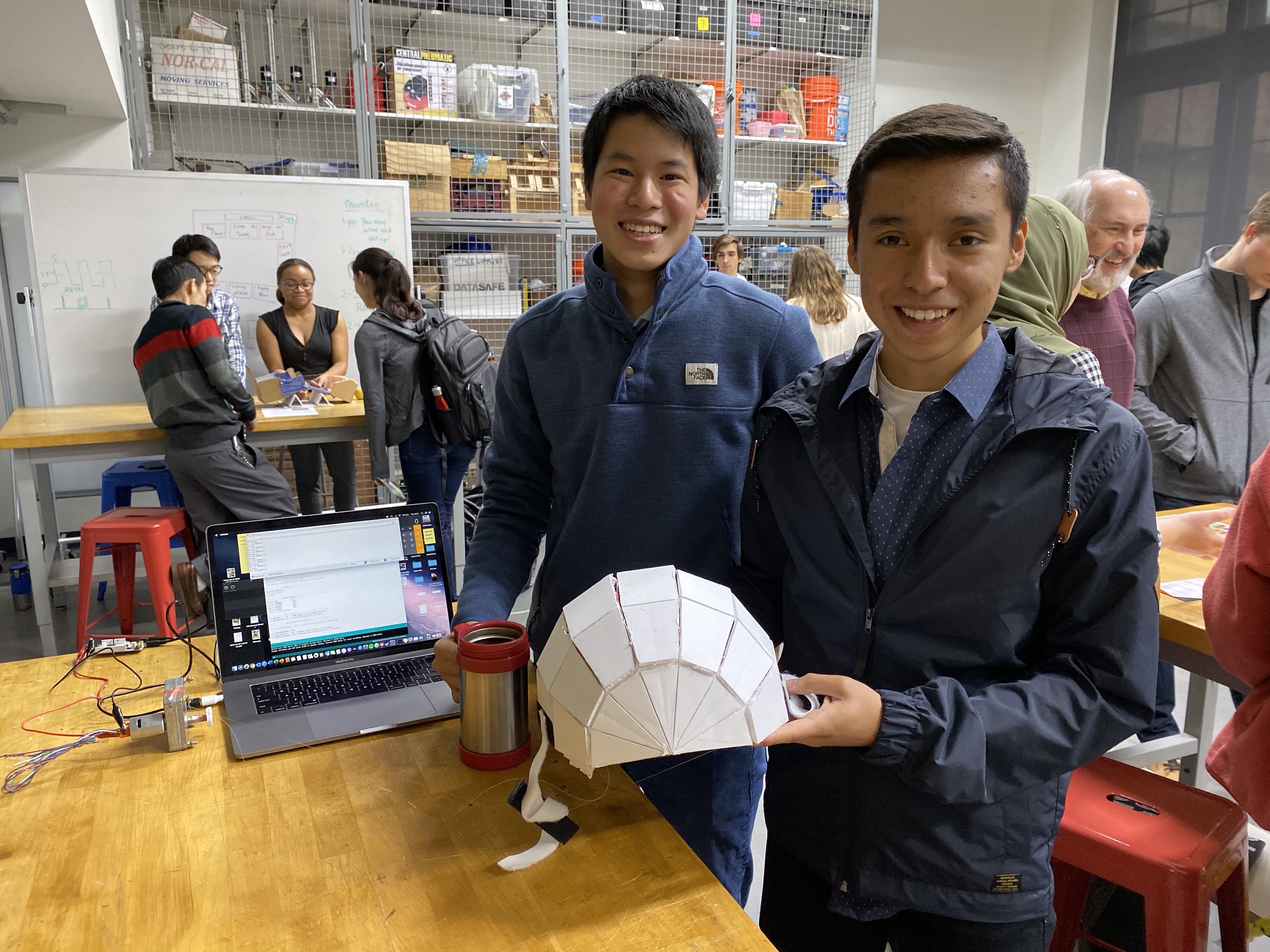
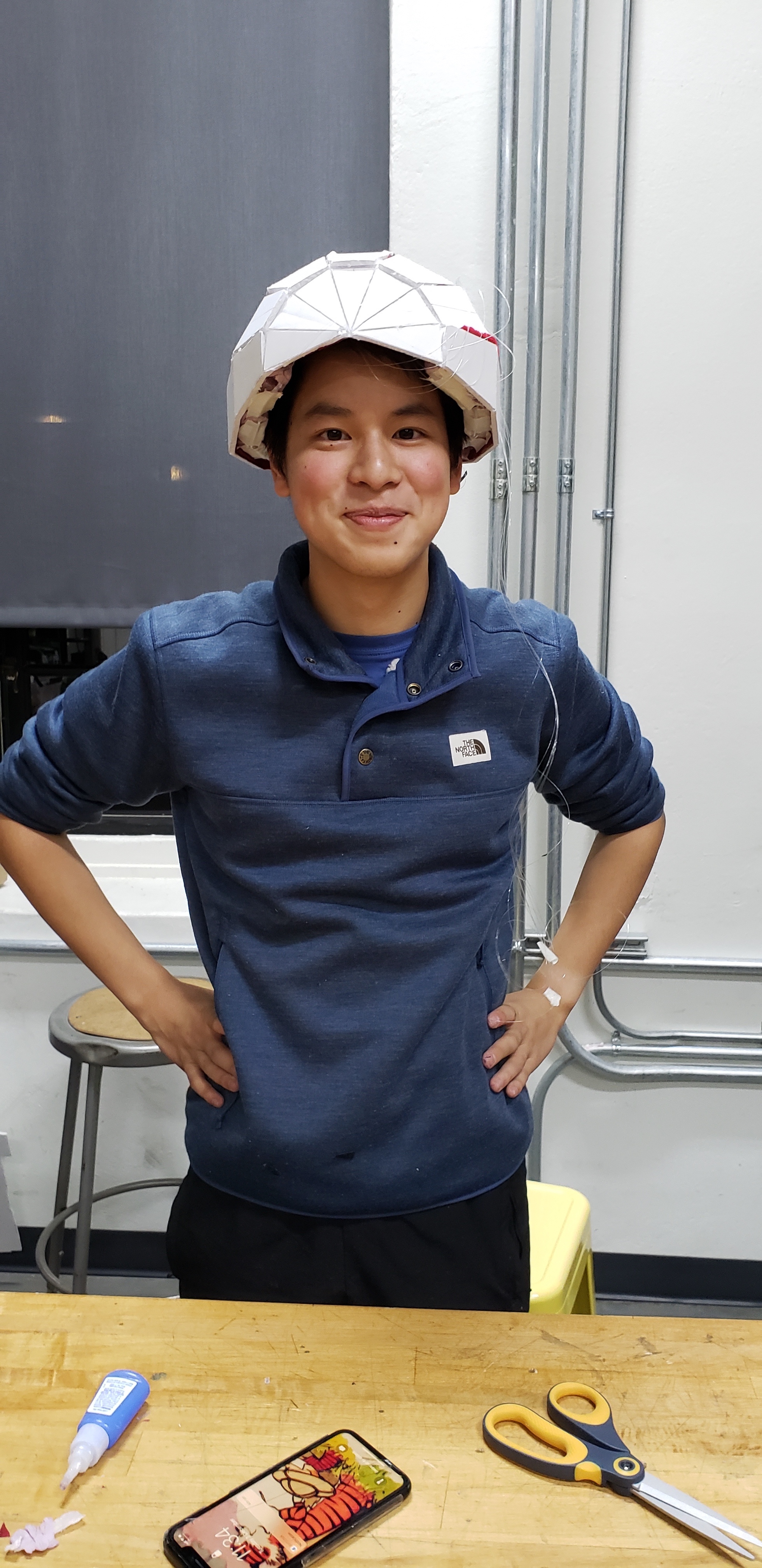
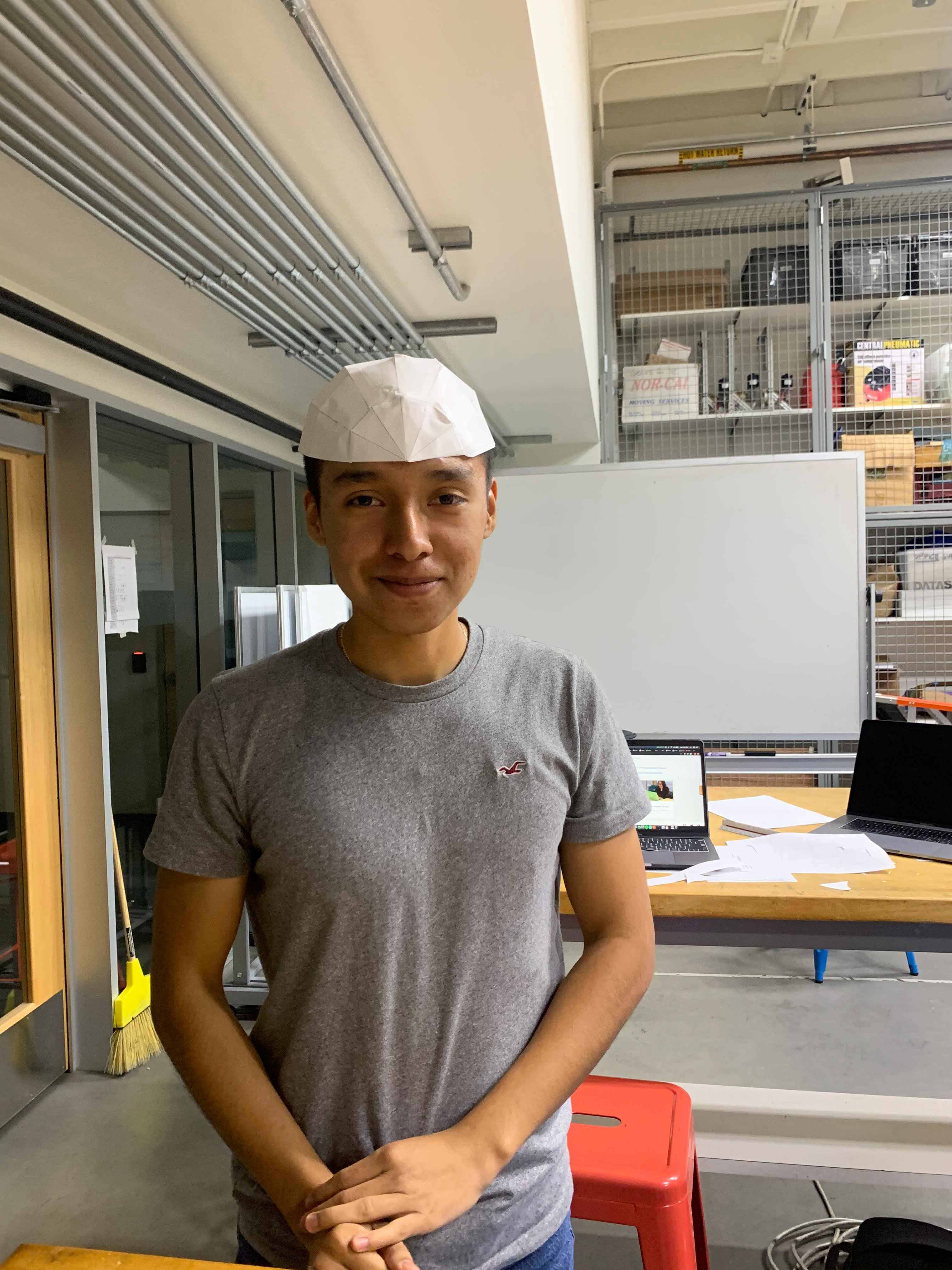
Caption:Senkai and Josue
with the Transformable Bicycle Helmet
Transformable Bike Helmet
Project team member(s): Josue Solano Romero and Senkai Hsia
Summary
The Transformable Bike Helmet seeks to increase the ease of using a bike helmet, and thus reduce injuries from higher usage by cyclists. The project uses soft robotics principles of localised compliance through flexures and motorised cable driven actuation to cause a 3D helmet to be formed from a 2D flat geometric net. When fastened, the helmet retains its 3D shape and provides crash safety. It can be easily be unfolded to enable easier storage as a flat surface. With future improvements to the geometric net and cable actuation system, this project could form the basis for a marketable collapsible helmet device.
Introduction
Most users of bicycles understand that wearing helmets are essential for safety, with studies showing it reduces the risk of serious head injury by up to 70%1. Yet despite advancements in accessibility - such that light and effective helmets are now available for under $302- bike helmets are still not being worn. In 2014, 60% of injuries in the United States on bicycles were by individuals not wearing helmets.
This has a particularly pernicious impact here on Stanford�s campus, where the main mode of transport is on two wheels. Students are notorious for flouting the rules of the road (especially on the roundabouts) and often do not wear helmets. These lax safety standards and the high volume of cyclists and pedestrians in rush hours leads to an estimated 300 serious accidents occurring each year3.

Stanford students without bike helmets
After one of the authors was nearly run over one evening, we decided to use our project to seek to increase the usage of bicycle helmets. Through personal experience and interviewing others, we realized that the problem stemmed not from a lack of access or knowledge, but rather that the form factor of traditional helmets discourages use. As a bulky, rigid, and curved ovoid structure, helmets take up a large volume and are impractical to store. This results in many cyclists believing, especially over short trips, that wearing a helmet is not worth the time or effort to carry around once they reach their destination, or that it might be stolen if left attached to their bike4. This perceived inconvenience combined with human propensity to systematically underestimate risk5 leads to helmets not being worn and worse injuries.
Thus the idea for the Transformable Bike Helmet emerged from whether it would be possible to create a helmet that could be transformed from a 2D surface to a 3D curved helmet. A flat surface would take up less volume and would be easier to store in a bag. This would encourage more users that bicycle helmets were less of an inconvenience but an easily carried device that is essential for their safety.
Soft robotics design principles represented a good approach to generate such a solution as soft robots utilize flexible materials and control mechanisms. Therefore, our project utilizes flat and folded origami-inspired geometric nets, with a motorized cable-driven actuation mechanism to pull the net into a cavity to hold the head. While the materials used are not strictly soft, the folds and cable drive mechanism enable the normally rigid foam to behave in a flexible manner suitable to be classed as a soft robot.
Background
Collapsible Helmets
The idea of a collapsible helmet has been gaining traction in recent years. The first was the Motorika Snapit introduced in 1997 (see below). However, technologies such as 3D printing and CAD software have only advanced in recent years to create lightweight structures that could be folded and provide sufficient crash safety. A number of startups have been working on helmets that can be reduced in size substantially, such as Morpher which collapses down to 3 inches, and FEND which collapses to ⅓ of its original size6.
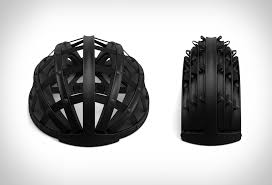
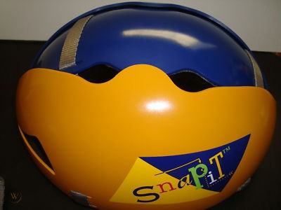
Left: Morpher Helmet, Right: Motorika Snapit
However, the most recent innovation in collapsible helmets has come from the EcoHelmet7, which won the James Dyson Award in 2016. This design is made from paper with a honeycomb structure that folds out from a center to cover a user's head and provides stiffness in collisions. The EcoHelmet captured our imagination with its portability, lightweight and soft material properties through the structural folds in the paper, a traditionally rigid material.
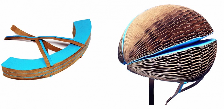
EcoHelmet
Going forward, we saw two things we could contribute. The first was a soft robotic actuation mechanism that could cause a helmet to transform from its collapsed state to its full 3D structure. The second was that many of these designs still occupied substantial 3D space and were not fully flat - we sought to create a structure that would be more akin to a flat sheet rather than a compressed version of the helmet.

Excerpt from Headkayse Ltd. Bike Helmet Patent, see references 14
Origami-Inspired Robots
Origami-inspired soft robots have been a major research area in the field of soft robotics. This is because the use of folds can modify a materials� compliance from rigid to flexible and thus be more adaptable to changing environmental conditions. This is through creating a flexure in a material (see below) that enables a joint to be locally compliant in a specified degree of freedom. Researchers at Harvard in 2008 investigated different crease patterns to achieve multiple degrees of folding8.

From Allison M. Okamura Week 2 ME23 Presentation
More recently, researchers at Harvard, MIT, and Caltech have utilized this concept to create a �self-folding robot� that utilizes localized compliance and temperate driven Liquid Crystal Elastomers9, with the benefit being it can be actuated passively with no external power source. Thus the use of flexures has been well understood in existing literature as a means of creating flexible properties from traditionally non-compliant materials.
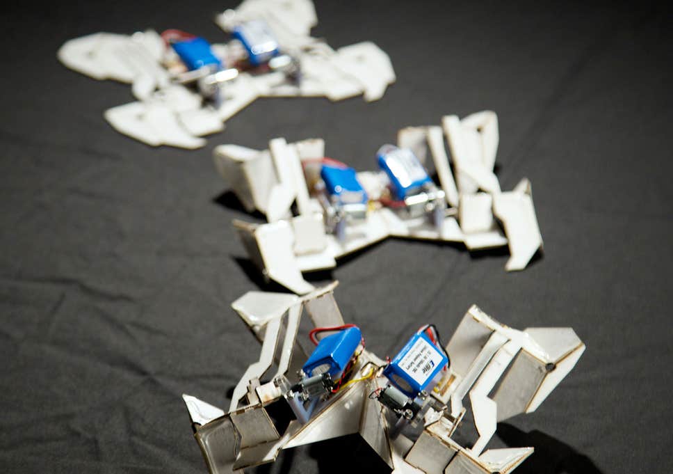
Self-folding robot 9
Cable Driven Actuation
Cable driven actuation has been a studied mechanism for controlling the degree of folding in flexures. More recent scholarly work has been focused on applications regarding surgical robotics10, but cable driven actuation mechanisms have been used to create robotic �fingers�11 since the early 2000s.
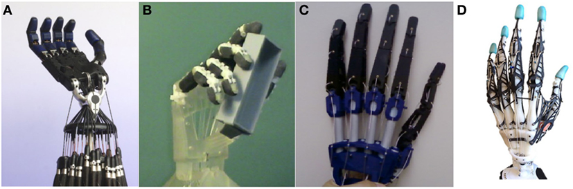
Finally, easily constructible designs for cable actuated soft robotic elements are available on Harvard and Trinity College Dublin�s open-source Soft Robotics Toolkit: https://softroboticstoolkit.com/. Their Shape Deposition Manufacturing finger uses soft materials actuated by a cable. It is based on work from Harvard (Dollar & Howe, 2006)12 and Stanford (Binnard & Cutosky, 2000)13 to form compliant fingers.

Shape Deposition Manufacturing Finger From Soft Robotic Toolkit
Going forward, we saw that we could use cable-driven actuation combined with flexures in foam or board to enable these materials to fold up into the desired shape from a flat surface. These would aid the construction of prototypes to model and refine our design.
Construction
Initial Designs
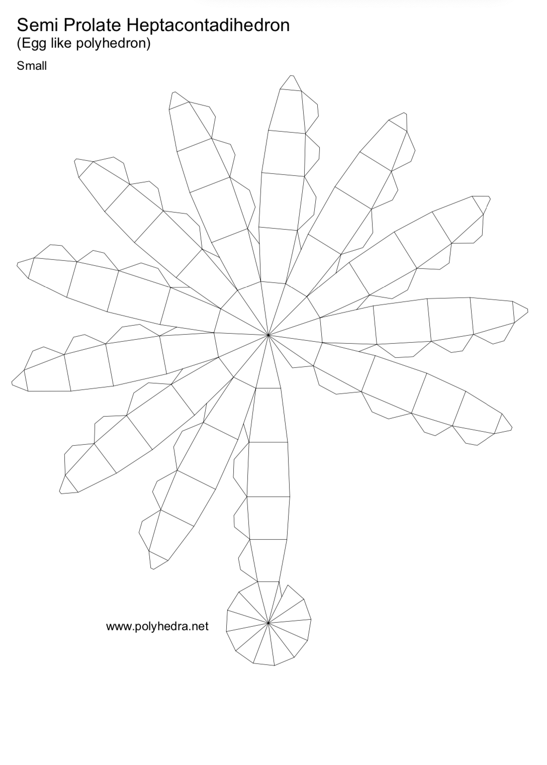
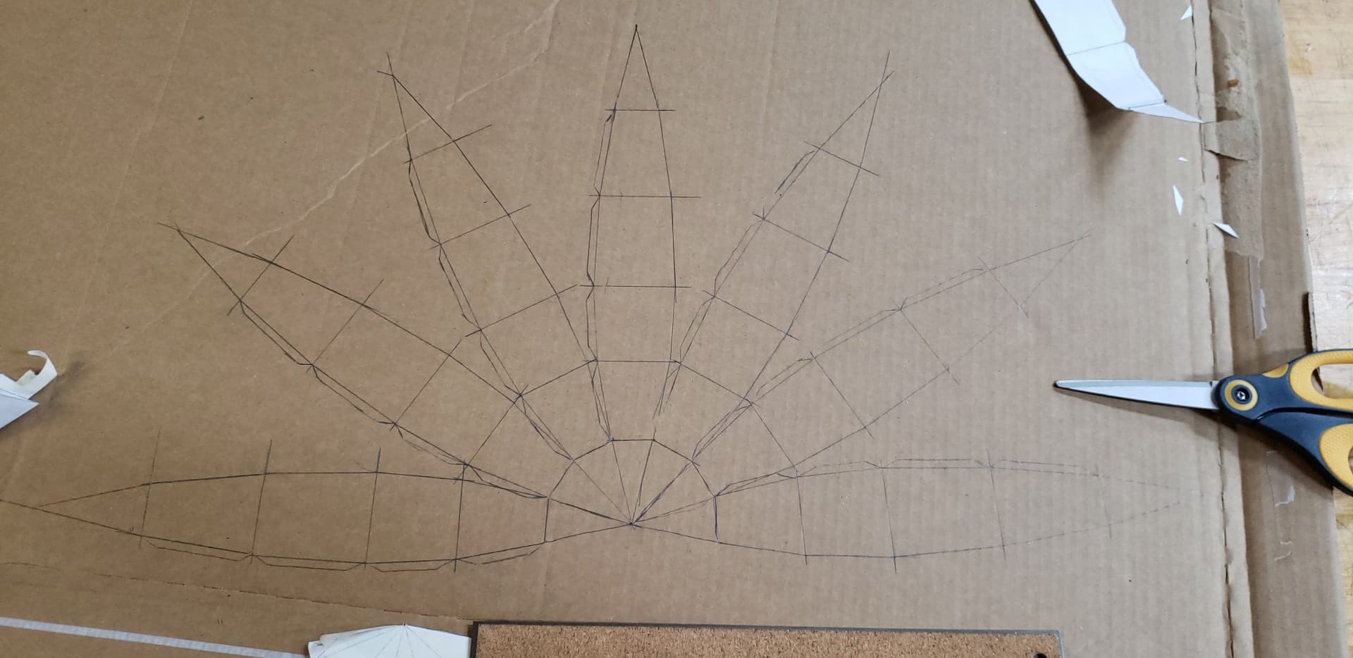
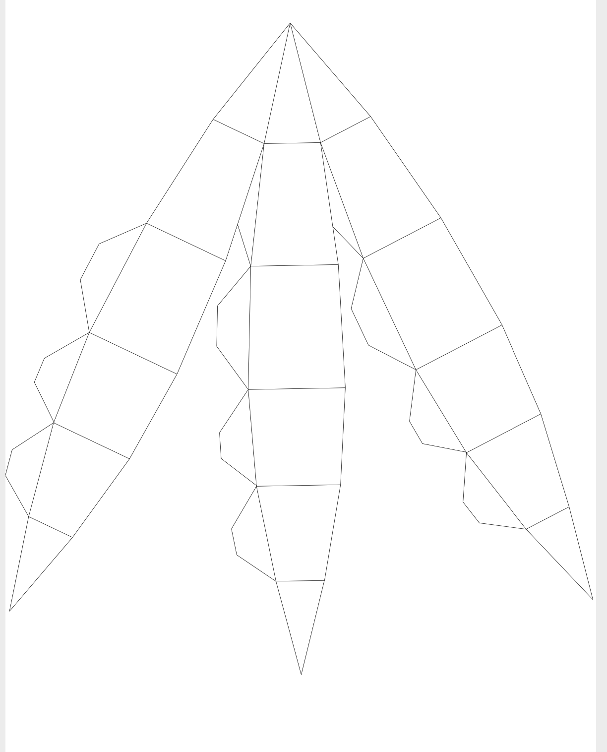
As described above, the characteristics of soft origami robots provided flexible structures, and through actuation, they can provide rigidity. These principles are essential for a compact transformable structure as they enable folding in multiple degrees of freedom. In origami, a 2D plane is folded into a rigid 3D object. With these principles in mind, the design of the Transformable helmet uses a 2D net, with specific flexures points, to create a Semi-Heptacontadihedron. This shape was chosen as the basic design for bicycle helmets is that they are half of an ovoid (i.e. like an egg), and a Heptacontadihedron represented the closest geometrical approximation for this shape.

This geometric net formed the initial basis for our design: see References section in first checkpoint.
To create the net of our Transformable structure, we referenced an existing 2D net designs of a Semi Prolate Heptacontadihedron (see Checkpoint 1). The original design creates a full Heptacontadihedron; for a helmet, we only need half of the design. Instead of using the original design, with Adobe Illustrator, we redesigned the net to contain seven finger-like structures. In addition, we removed unnecessary tabs along the sides of each section. See the scaled.ai adobe illustrator file and templet used in the design under the reference section.
Assembly
This redesign is made to allow for simple cable-driven actuation. Throughout each finger, there are specific marks and flexure points in the design. These folds are consistent throughout each finger to create a symmetrical Semi Heptacontadihedron structure. If one folding section is misaligned, it will affect the entire 3D structure as each section depends on the consistency and accuracy of adjacent finger structures.
After transferring the 2D net onto cardboard, we created flexure points in the material. A stiff plane is necessary for the backbone as it is simple to control the degrees of freedom through flexure points. In our final prototype, we used foam board and created creases by etching through half of the thickness of the material.
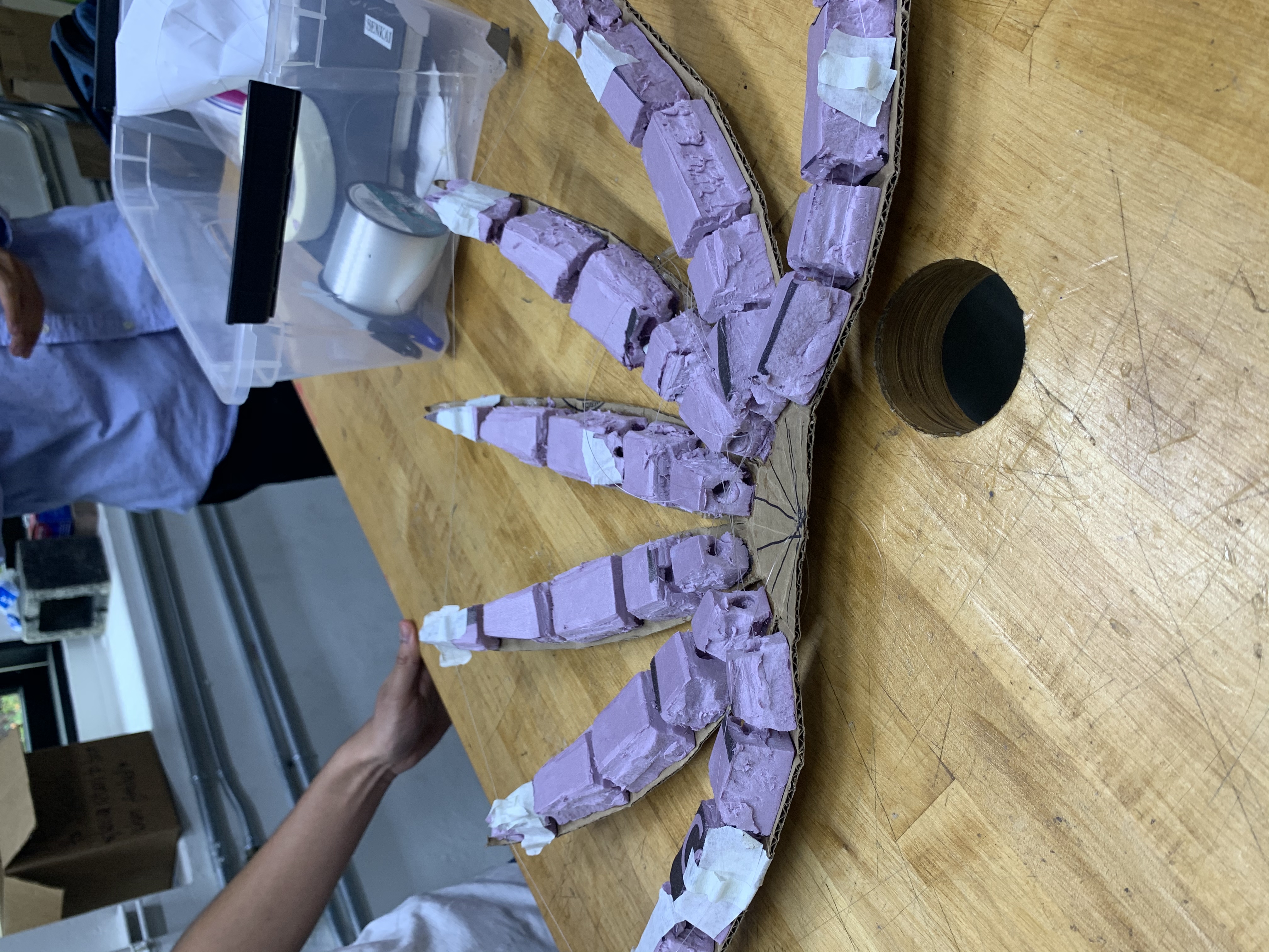
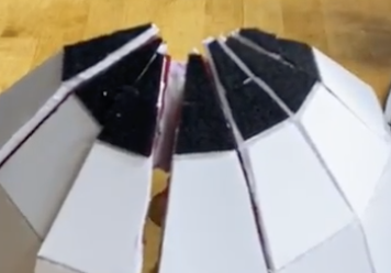
Our first prototype: see the foam pieces and cardboard backbone.
In order to provide protection, helmets consist of a layer of foam that increases the time of impact between a person�s head and a solid structure. To simulate the integrity of a functional helmet, we included individually cut out pieces of insulating foam between each folding section. In total, there are 35 foam pieces. These foam pieces can not overlap flexure points as it will intervene with the final actuation of each finger. Each foam piece is tailored to fit its specific section and super glued to the cardboard backbone.
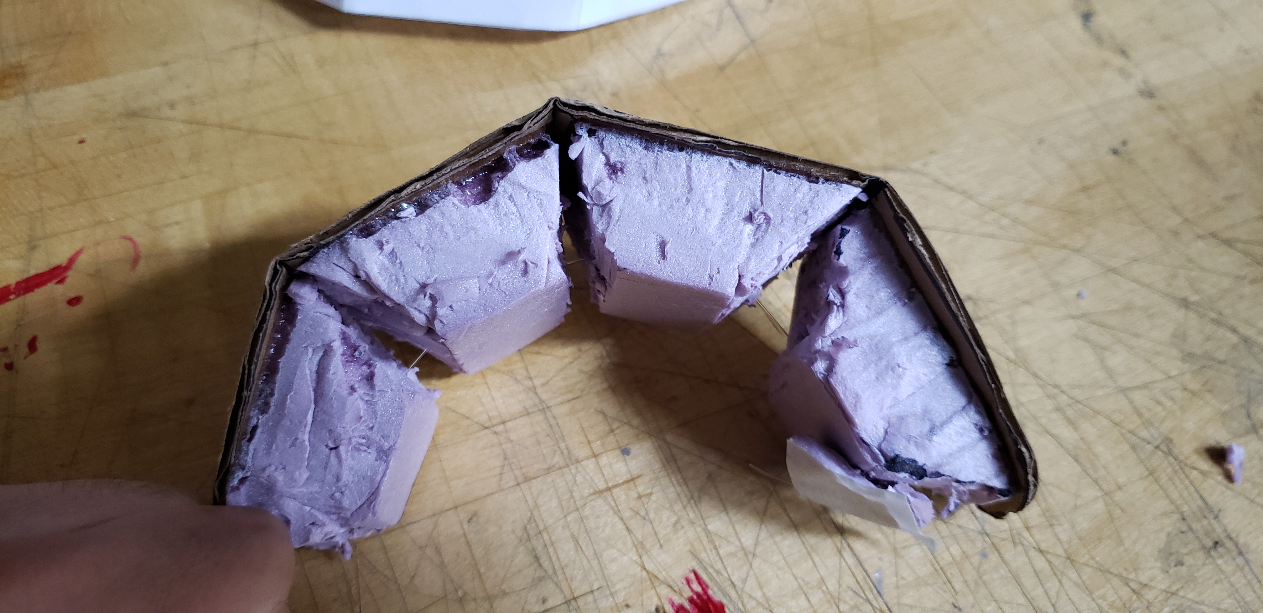
In addition to providing protection, each foam piece serves as a supporting structure to the final curvature of each finger. When actuated, the foam pieces increase the structure of each finger. The foam pieces are manufactured with an angle at each end to create a trapezoid; When the foam pieces coiled, they form an arch structure.
Prototypes and Testing
In our original design, each finger was threaded with cable along the center. The cable can be threaded through the trapezoid pieces, or they cable be threaded through plastic tubes. This actuation is directly inspired by robotic fingers found in scholarly work. When actuated, the folds along each section bend in the direction of the applied force. As there are seven fingers, each section is actuated independently of the actuation of adjacent sections. At first, this design proved to be promising because it provides precise control of each finger. However, later testing revealed that synchronizing the actuation between each finger is a difficult task.
Prototype 1: Hard to control folding up the fingers.
In order to actuate each finger, we combined each cable to one thread. By doing so, we can tighten one cable, and all seven fingers would actuate; this method is complicated and only works if all seven fingers are actuated at similar rates. In this project, each prototype is manufactured by hand, meaning that imperfections affect the overall performance. In a perfect environment, actuating each finger through one cable would create the perfect rigidity of the Transformable helmet. To compensate for imperfections in the manufacturing process, we threaded a cable along with the tips of each finger in a loop When the cable it tighten, all �fingertips� meet at a specific point. Having a cable across each finger creates a constant actuation rate (see Mechanism section for a more detailed explanation).
See the video below: https://youtu.be/CT1r2REyuTI
Final Design and Modifications
After discovering the effects of one uniting cable along each finger, we incorporated it into the final design, eliminating the independent cables on each finger. Although, we found that having a cable on each finger is useful in the assembly stage as a calibration tool. Depending on the structure of the trapezoid foam pieces, the curvature of each finger will vary. The foam pieces are tailored to match the curvature of the adjacent finger.
In the final design, we included a fabric sheet on the backbone of the Transformable board. The fabric serves as a backup hinge mechanism if the foam board where to rip. Fabric sheets have multiple degrees of freedom and are commonly used throughout soft robotics.
To maintain the actuated Semi Heptacontadihedron 3D structure, we added velcro along with the tips of each finger. This way, once the velcro is in place, there is no need for force on the cables. Velcro can also be used as straps to sustain the helmet on the user's head.
Actuation
To actuate the device, we used a motor connected to a 12V power supply. The motor was controlled by a Hapkit board and we used existing code taken from the CharmLab Vine robot project which was kindly provided by Laura. The code can be found in the files section below. For the demonstration, the motor control was manually inputted, but a future iteration would have a set time for actuation depending on the size of the helmet.
List of Components and Total Cost
Foam board 2 in x 2in = $3: Fishing string = $2.50: 1mm x 5ft plastic tubing = $1.10: Pink insulation foam = $27: Foam = $5: Fabric = $5: Velcro =$3: Arduino motor = $4: Total Cost: $50.60
Results
Mechanism
The mechanism for the soft robot utilized a combination of flexures and cable driven actuation to fold the flat geometric net into a cavity. The flexures were comprised of horizontal cuts into 2mm foam board and a fabric being laid over the joint. This allowed the foam board to rotate about each joint in one degree of freedom. The cable driven actuation mechanism was designed so that it went along the length of the two outermost fingers and then across the tips of all fingers to form a �loop� around the net (see below). A plastic tube glued to each tip allowed the cable length to be increased or decreased in length along its path.
See the black path for the path of the cable loop through the device.
When the two ends of the cable were attached to the motor assembly, this allowed the cable length to be contracted when the net was held in place and the fingers curved to form the desired shape.
The first step of the mechanism is that by holding the net stationary, this created a reaction force exerted by the net on the contracting fingers. This allowed the cable to contract along the length of the fingers rather than causing the net as a whole to move in the direction of the motor pulling the cable.
As the cable contracted through the tips of each finger, this caused the effective radius of the �loop� of cable through the helmet to decrease. This meant that the length of each finger from the base of the net to the tip needed to decrease and thus the forces acted inwardly along that length seeking to compress the finger. As the effective distance between each segment of finger needed to be smaller, this resulted in bending along the flexures which caused the fingers to curl upwards. The curvature of each finger was regulated by the geometry of the foam pieces for each segment because when foam pieces of two segments met, this created a reaction force to oppose any further bending along the flexure. As the flexures could not be bent any further, this prevented further curvature of each finger. Careful measurements and cutting ensured that the maximum curvature - where all the foam pieces met and were fully compressed - was consistent across all fingers. Upon maximum compression, the back attaching piece enabled the helmet to hold its shape even when no longer attached to the motor.
Note the decrease in radius of the �loop of wire as the cable is actuated
The �loop� arrangement of the wire was successful to ensure an even actuation between the fingers (compared with the unsuccessful lengthwise actuation attempted with the first prototype) for three reasons. The first reason is that by using the looped path, the starting distance between each finger was much more consistent, whereas the lengthwise actuators had different lengths of wire and hence needed to be individually adjusted. The second is that as the two ends of the wires are contracting at an even rate, the rate of decrease in radius and distance between each tip was more constant and consistent. Hence the rate of contraction and curving was much more even across the fingers. Finally, if a finger curved to its maximum faster than other fingers, it would be held in place by friction with the other fingers beside it. This allowed all the fingers to eventually curve to their maximum without being blocked by another finger overextending too rapidly.
The combination of the loop cable path and the flexures ensured an even convergence both along the length of the fingers but also simultaneously along the curvature of the loop. This enabled the single motor to drive the cable of the helmet and cause it to fold in an even manner.
Performance and Testing
The transformable helmet performed well during the demonstration day - it functioned repeatedly and successfully showed the concept of a 3D helmet being formed from a 2D surface. No numerical tests were conducted on the device due to a lack of time, however we found the motor needed to use in excess of 7 volts to generate enough force to actuate the device. Additionally, whilst no compression tests were able to be taken to ascertain the crash safety of the helmet, the foam pieces under compression enabled the fingers and the helmet to be rigid and hold it shape once the back pieces had been successfully attached.
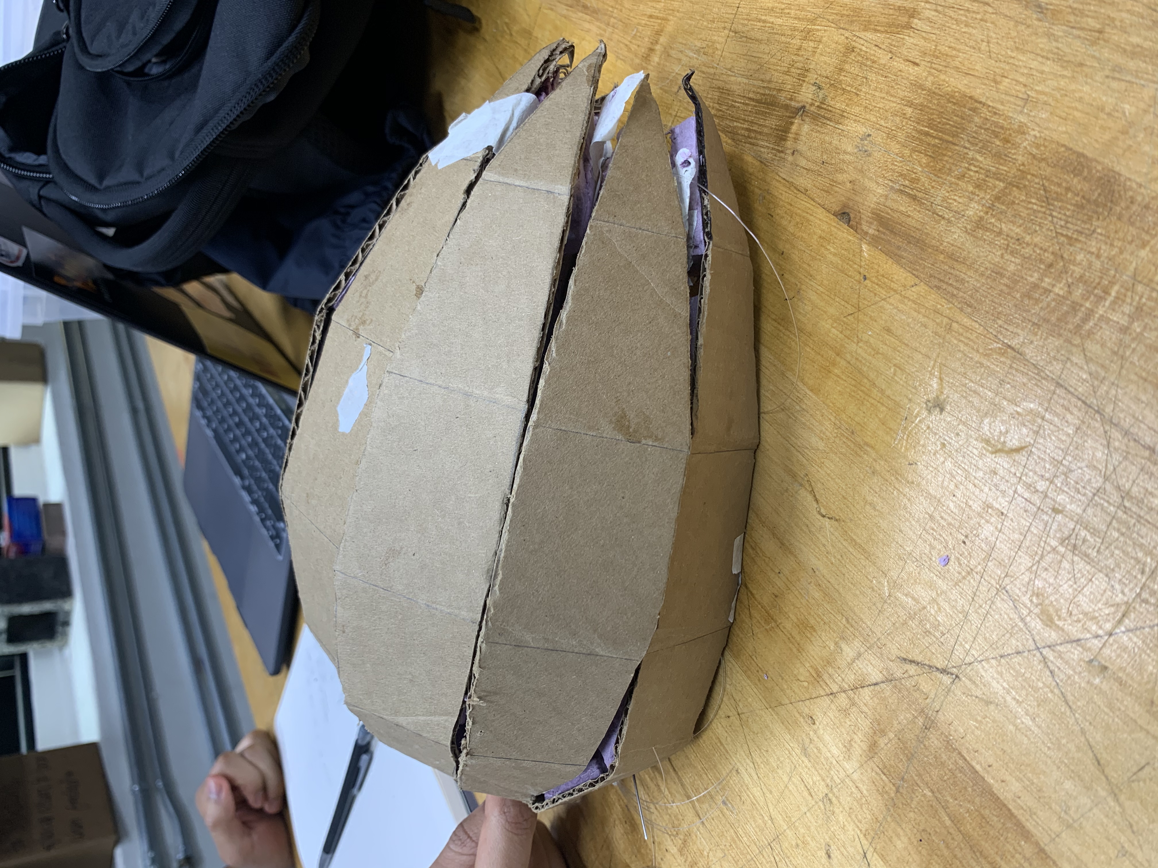
Qualitatively, the mechanism enabled the device to actuate evenly such that all the tips converged at almost the same time, and the curvature of each finger successfully formed the cavity required to fit a users head. The form factor of the resulting shape did resemble traditional bicycle helmets and was able to be secured by the strap.
The main shortfall was that the geometric net still took up a lot of space. We realized that this was something that could be later refined through future designs but that the second model had achieved its aim as a successful proof of concept.
Future Improvements
There are several improvements that could be made to our project.
The first area of improvement would be refinements to our geometric net. The most important would be to create a design that would use less space when flat so that it would be easier to store, and so that when folded would provide a better fit to the head. This could be done through using fewer fingers and shaping them to fit the geometry of the head more closely, such as the example shown below that has been patented. The design could also be customised for specific user head shapes with custom measurement in length to provide a closer fit. Future iterations could include a hard plastic shell in between flexures to provide a hard and waterproof outer coating, or be made of our a stiffer and durable fibre such as nylon.
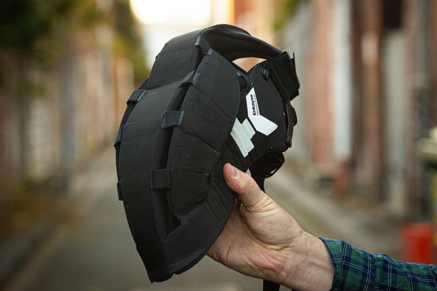
HeadKayse One Helmet from Headkayse ltd.
The second area of improvement would be increasing the speed and reliability of the actuation mechanism. A number of visitors asked about the high tension in the cable during winding - we would seek to reduce the tension acting on each individual cable by adding multiple cables in parallel. This would reduce the risk of fracture and could allow for an increased net force to fold the net. We would also look to increase the power to weight ratio of the motor used. Instead of an actuation system that was separated from the helmet, we would seek to add a lighter motor attached to the helmet that could actuate the cables. We would also seek to increase the rotation speed of the motor to reduce the time taken to actuate the helmet, and to measure a precise length of time required for different sizes of helmet to actuate fully.
A third area of improvement would be to make the user experience easier. We could create a back attaching piece that was directly tied to the helmet to prevent it being easily lost. We would also investigate how to incorporate an improved fastening mechanism more akin to traditional helmets which would be more easily adjustable to create a tighter fit for users.
Application
The ideal user experience would be for the robot to be taken out of a bag as a flat surface, then for the user to activate the motor which would cause the helmet to fold up. The user would then attach the back fastening piece, adjust the straps to provide a comfortable and secure fit, and be off on their way. To store the helmet, the user would then unclasp the back piece, unspool the motor and pull on the outer fingers to stretch the helmet into a flat piece. We envision that the process with improvements to our original design to enable easier storage and faster actuation would ideally take between 10-30 seconds.
This process would allow us to achieve our humanitarian objectives by providing a quick and efficient way to store bicycle helmets when not in use. Overcoming the excuse that helmets are impractical to wear and carry whilst providing a safe and lightweight design we hope would encourage more users to wear helmets on a regular basis and on rides of shorter distances. Similar to how retractable umbrellas are easily carried inside bags and are not seen as inconveniences on rainy days, we envision our helmet as being an essential and readily available tool for cyclists to carry and prevent injury to themselves and others.
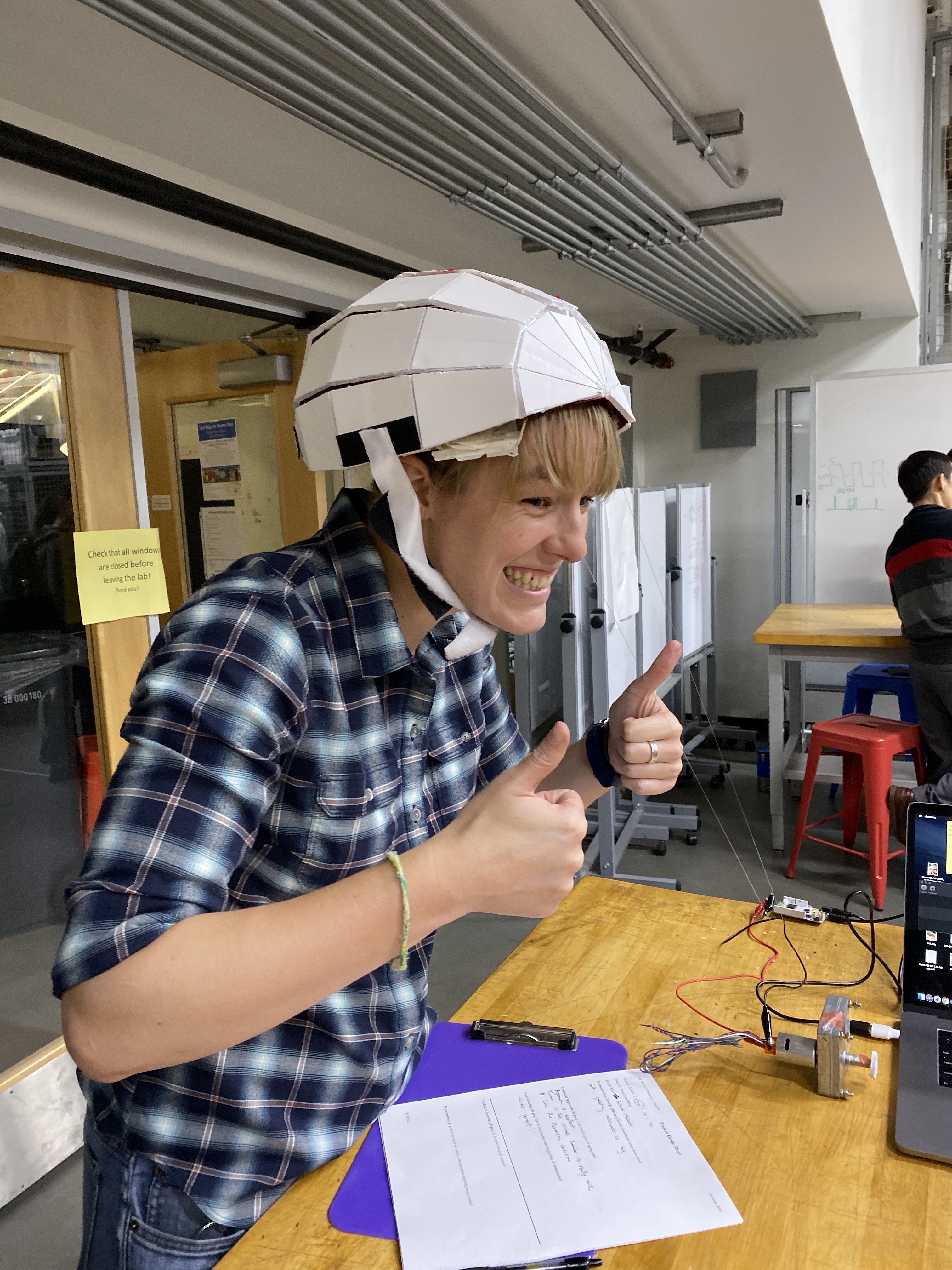
An enthused Laura modelling the project at the demo day!
Acknowledgments
We would like to thank Professor Okamura, Laura Blumenschein, Tita and Ali for all their support and encouragement. From spending hours going over the motor code to getting our supplies, completing this project and enjoying this course would not have been possible without all your help.
Files
- File 1 Arduino Code for Motor: Attach:Motor.ino.zip
- File 2 Adobe Illustrator File: Attach:scale.ai
- File 3 Templates used to cut out foam: Attach:Scale3.pdf: Attach:Scale 2.pdf: Attach:Scale1.pdf
References
1] Jake Olivier, Prudence Creighton, Bicycle injuries and helmet use: a systematic review and meta-analysis, International Journal of Epidemiology, Volume 46, Issue 1, February 2017, Pages 278�292, https://doi.org/10.1093/ije/dyw153
2] https://bicycleuniverse.com/five-bicycle-helmets-under-100/
3] Sam Kurland, SUPDS warns of biking dangers, The Stanford Daily October 2013 https://www.stanforddaily.com/2013/10/11/sudps-warns-of-biking-dangers/
4] Ruben Carbonero, Quora https://www.quora.com/Why-do-some-people-not-wear-a-helmet-when-they-bike
5] Tara Baker-Pope, Wrong About Risk? Blame your Brain, The New York Times, January 2008 https://well.blogs.nytimes.com/2008/01/16/wrong-about-risk-blame-your-brain/
6] Josh Palmer, Folding Bike Helmets, Bikeroar http://www.bikeroar.com/articles/folding-bike-helmets-are-they-safe-practical
7] Ecohelmet by Isis Shaffer https://www.ecohelmet.com/
8] E. Hawkes, B. An, N. M. Benbernou, H. Tanaka, S. Kim, E. D. Demaine, D. Rus, R. J. Wood, Programmable matter by folding, Proceedings of the National Academy of Sciences Jun 2010, DOI: 10.1073/pnas.0914069107
9] ARDA KOTIKIAN, CONNOR MCMAHAN, EMILY C. DAVIDSON, JALILAH M. MUHAMMAD, ROBERT D. WEEKS, CHIARA DARAIO, JENNIFER A. LEWIS, Untethered soft robotic matter with passive control of shape morphing and propulsion, Science Robotics, August 2019
10] Mark Runciman, Ara Darzi, and George P. Mylonas, Soft Robotics in Minimally Invasive Surgery, Soft Robotics 2019 6:4, 423-443
11] Tian L, Magnenat Thalmann N, Thalmann D and Zheng J, The Making of a 3D-Printed, Cable-Driven, Single-Model, Lightweight Humanoid Robotic Hand, Front. Robotics 2017 AI 4:65. doi: 10.3389/frobt.2017.00065
12] A. M. Dollar and R. D. Howe, �A robust compliant grasper via shape deposition manufacturing,� IEEE/ASME Transactions on Mechatronics, vol. 11, pp. 154�161, 2006.
13] M. Binnard and M. R. Cutkosky, �Design by Composition for Layered Manufacturing,� Journal of Mechanical Design, vol. 122, pp. 91�101, 2000.
14] Creak, A. Walker, T. Redman, A. George, F. ''United States Patent No. US2018/0192730 A1.
Checkpoint 1
A) Find and create a model of the bike helmet from a geometric net. B) Demonstrate that the model can be formed from a 2D plane into a 3D object. C) Create a prototype of the actuation mechanism that transforms the plane into a 3D structure.
For checkpoint 1, our group found a working design for a helmet-like structure and we created a working prototype of a single robotic strip.
A) and B) : Hemi - Semi Prolate Heptacontadihedron Net?
The design of our helmet resembles the net layout of a Semi Prolate Heptacontadihedron1. When the pieces are folded they form an ovoid. Using half of the net layout, we created the design for our helmet.
Semi Prolate Heptacontadihedron
C) Cable Actuated Fingers
Next, we created a foldable cable actuated "finger." When one end is held down, Eventually, the helmet will be composed of several fingers that wrap around to form an ovoid Using a design from Soft Robotic Toolkit2, we replicated a design out of foam and cardboard.

Here is a video of our prototypes:
For SoftRoboticsToolkit SDM Finger Fabrication Guide and the geometric net see references.
References
1) Paper Models of Polyhedra website: https://www.polyhedra.net/en/model.php?name-en=hebdomicontadissaedron
2) SoftRoboticsToolkit https://softroboticstoolkit.com/resources-for-educators/sdm-finger?fbclid=IwAR12CLQk1CMPxdt_0uoHe1uk1XyWSGa-TTOBbtxrsA1Mrv_xCasFlE0k_zk
Checkpoint 2
For Checkpoint 2, our goal was to build a prototype with a functioning model of the folding mechanism.
A) Design
Using Adobe Illustrator, we created a 2D template for the Heptacontadihedron. We then traced this out on cardboard to cut out the "backbone" for the prototype. We increased the number of "segments" from 5 to 7 compared with the original model as we realised we needed more to cover the entire head sufficiently.
B) Construction
Using our first cable actuated model, we cut out and drilled foam pieces for the entire prototype.
In order to create the curvature of the helmet, we wired each segment of the design. Each wire is attached to the end of a pice and when tightened, the segment curls. The goal is to tighten each wire so that all of the segments curl at the same angle. In addition, each segment needs to bend at the same time so that they all meet at the same spot.
C) Calibration
One of the challenges with folding each segment into a Heptacontadihedron is celebrating the length and tensions of each wire. Each segment is built with different imperfections and this affects the synchronous of each fold. To compensate for the imperfections, we added wire along the tips of each section. When tightened this wire ensures that all pieces meet at the same spot.

Therefore, when the strings are tightened, the horizontally wired tips cause the helmet to curve into the 3-D shape, and the vertical strings cause the tips to fold in and the segments to contract and thus form the shape of a bicycle helmet.
In this prototype, we found that the wire along the tips improves the final Heptacontadihedron structure. Finally, we added velcro to the ends of the backbone to allow the user to adjust and to hold the structure of the helmet.
