

Nadin Sochima
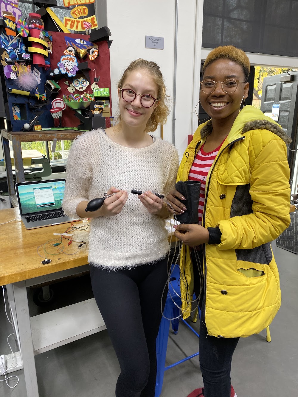
Nadin and Sochima
with their Pneumatic
Leg Band.
Pneumatic Leg Band for Navigation to Assist the Visually Impaired
Project team member(s): Nadin Tamer and Sochima Ezema

Summary
Our soft robot is a pneumatic leg band designed to assist visually impaired people with day-to-day navigation by giving them haptic feedback about their surroundings by putting pressure on different parts of their leg. It receives data regarding nearby obstacles from a proximity sensor and has three separate pneumatic bladders that can be individually inflated with a hand pump to give users guidance on which directions to avoid (left, front, or right). In testing, the leg band performed quite well: the proximity sensor was able to detect obstacles accurately and people who tried on the leg band stated that they could easily distinguish which direction the pressure was coming from. Some areas for further improvement include automating the feedback process, adding more pneumatic bladders for more precise feedback, and adjusting the Velcro positioning to ensure a better fit.
Introduction
We designed our robot with the goal of making day-to-day navigation easier for visually impaired people by providing haptic feedback about nearby obstacles, thus telling the user which directions to avoid. Haptic feedback is a good approach to this since it allows for more precise and reliable feedback. Imagine, for example, that auditory feedback was used instead: It would be much more difficult to provide precise feedback beyond “left” or “right”, while with haptic feedback we can get more precise by applying pressure to different parts of the leg (think front and right, back and left, etc.). Also, auditory feedback would be unreliable in loud situations whereas haptic feedback would be unaffected. Using a soft robotics approach to provide haptic feedback is especially effective since it can rely on the human skeletal structure as part of the robot (as we do when deflating the pneumatic bladders, see Results section), as well as providing a more comfortable experience for the user.
Background
While researching for our project, we examined several sources that considered the issue of designing a navigation system to assist the visually impaired. One paper that we found, called “Review Paper on Navigation System for Visually Impaired People” (by Chaitali K. Lakde et al.) discussed the advantages and disadvantages of several different such systems. One type of system Lakde et al. studied was similar to ours, in that it used an ultrasonic sensor to detect obstacles and provided mobility support instructions in “vibro-tactile form” (haptic feedback). They stated this form of feedback reduces navigation difficulties; however, ultrasound can result in less accurate localization if “walls ... reflect or block ultrasound signals”. Another paper (by the same authors) also focused on the potential haptic feedback holds: In “Navigation system for visually impaired people”, Lakde et al. proposed a new navigation system that combined auditory and haptic feedback. They stated that vibration is a “perfect indicator” for users with less hearing capacity, or in situations where the auditory feedback may be difficult to hear. Similarly, in "A Comprehensive Survey of Navigation Systems for the Visual Impaired", Kandalan et al. concluded that haptic feedback is "fast and familiar for visually impaired users", though it is limited in the amount of information can provide (it cannot, for example, provide information about street names/nearby buildings like auditory feedback might). That being said, the information that we found corroborated the idea that haptic feedback could be an effective way to warn the user about nearby obstacles.
However, none of the papers above discussed the possibility of using a soft robotics approach to creating a navigation system. On this topic, we found a paper by Skorina et al. which examined a “soft robotic wearable wrist device for kinesthetic haptic feedback”. They reported that “soft wearable haptics can conform to the user's body and apply feedback forces and torques while still remaining flexible to user motion and easily adapting to variations in user body dimensions”, confirming our hypothesis that haptic feedback remains a good option for our project. However, they did also find that in some situations, “the haptic feedback was not precise enough”. (The precision of the feedback given by the leg band would be an interesting avenue to explore as a possible improvement to our project.)
Construction
Our project involved constructing two separate systems: the pneumatic leg band and the proximity sensor system.
Components and Approximate Costs
Pneumatic Leg Band
- Heat-weldable Ripstop nylon $7.99
- Pneumatic tubing (different sizes - 4.5/32’’ and Ľ’’) $10
- Parchment paper $.50
- Push-to-connect adapter + splitter $5
- Zip ties (3) $.15
- Superglue $.50
- Pneumatic clamps $.50
- Hand pump $7.50
Proximity Sensor System
- Hapkit board $35
- Micro-USB cable $5
- Alligator clips $5.50
- U-shaped jumper wires $.20
- LED $.30
- Resistor (1 kΩ) $.10
- Proximity sensor $10.95
Pneumatic Leg Band
While making the pneumatic leg band that provides feedback to the user, we used techniques that we learned in Lab 4 (pneumatic wrist brace). To begin with, we sketched out a design for our leg band, which uses three separate pneumatic bladders rather than just one, as seen below.

We used our sketch to trace out the separate parts of the design onto paper to create the templates we would use to trace and cut our actual materials. The inner parts of the design (solid lines), which would eventually become the pneumatic bladders, were cut out from parchment paper while the outer part (dashed line) was cut out from heat-weldable Ripstop Nylon fabric. For the outer design, we traced two mirrored copies (by flipping the paper template over after tracing it out once) so that they would align when we welded them together.
Once we had all our pieces cut out, we stacked the two layers of fabric with the parchment paper placed between them as seen in our sketch and used a hot iron to weld the layers together. The parchment paper prevented the fabric from welding together, creating three “pockets” in the fabric that formed the pneumatic bladders. Finally, we stuck a piece of Velcro on each side of the leg band to allow users to easily put it on or take it off. (This was a recent development—we initially punched holes at the sides and used elastic cord, but found that Velcro made the process of putting the band on a lot easier.)
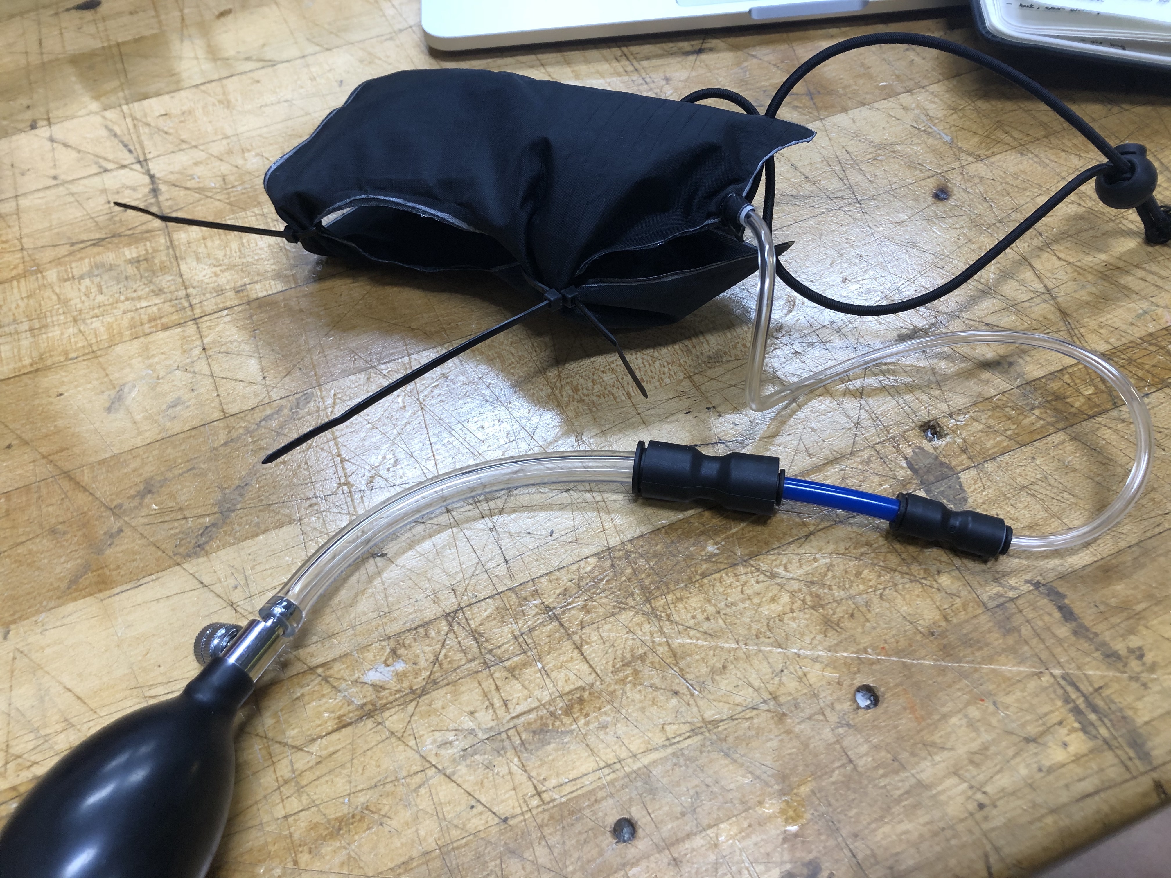
The next step after constructing the leg band was connecting it to a way to inflate the three pneumatic bladders (we used a hand pump for this purpose). For each of the three inlets on the leg band, we took around 3 feet of 4.5/32’’ pneumatic tubing, placed a drop of superglue on the outside of the tube near one end, and inserted it into the inlet. We also secured each of the inlets with a zip tie. Next, we attached a clamp to each of the three tubes so that we would be able to control the airflow into each bladder. Each of these three tubes was inserted into a larger, Ľ’’ tube. The three larger tubes converged in a four-way splitter, and the fourth tube was connected to a hand pump using a converter. We used this hand pump, along with the clamps, to individually inflate the three pneumatic bladders.

Proximity Sensor System
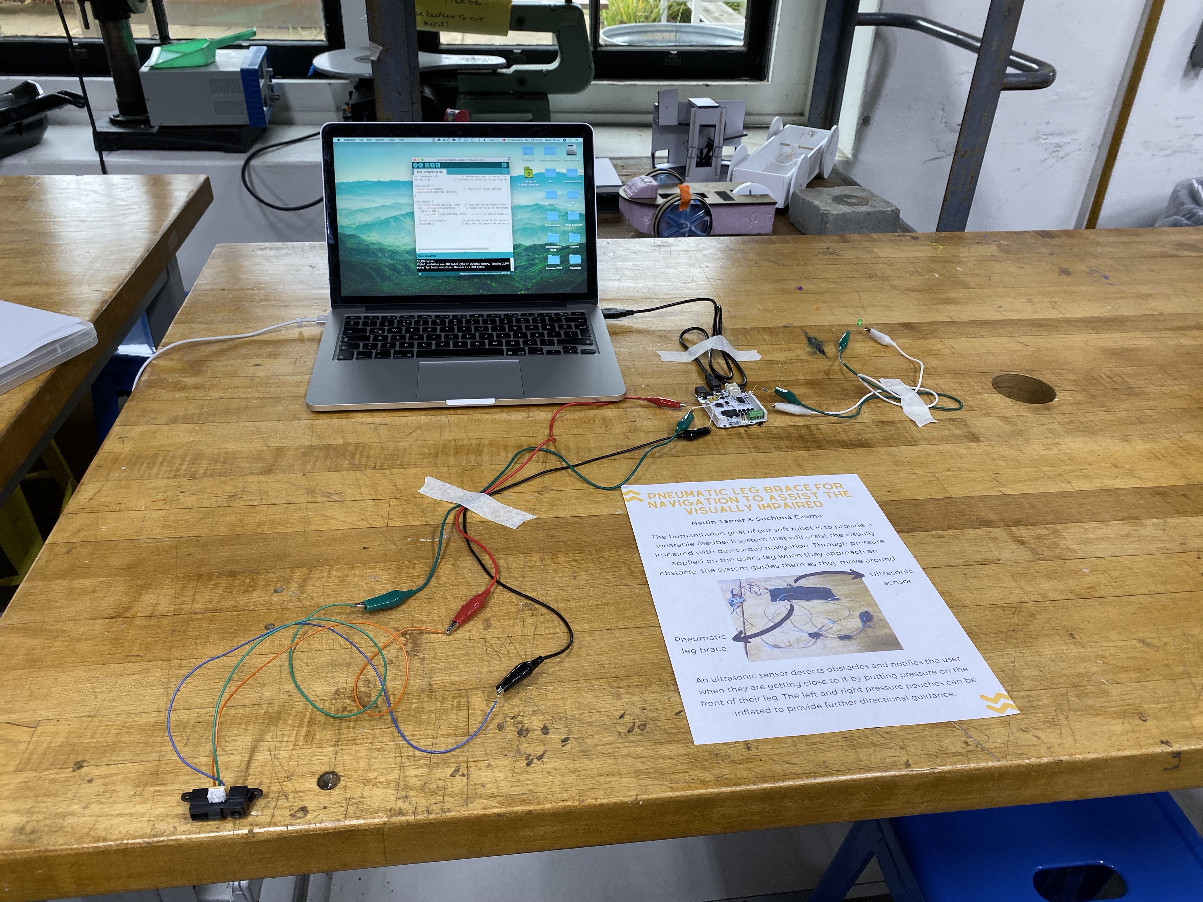
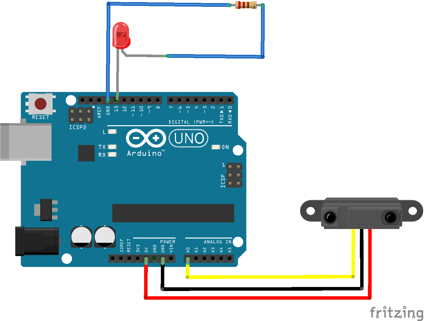
In addition to the pneumatic leg band, we also built the proximity sensor system from which it receives data. We used an analog distance sensor from Sharp which can detect distances between 10-80cm. In order to connect the sensor to our Hapkit board, we first had to solder three wires to it (a task the course assistants helped with--thank you!). Then, we used alligator clips and U-shaped jumper wires to connect the sensor to the Hapkit board as follows: When looking at the sensor from the back, the left connected to power (5V), the middle to ground, and the right to an analog input pin (A0). We also connected an LED with a resistor to give information about the sensor’s current input: The long leg (cathode) connected to digital pin 13, while the short leg (anode) connected to ground. Below, you can find a photo of the finished proximity sensor system as well as a diagram of the electronic circuit (although the diagram uses an Arduino board rather than a Hapkit one, the pins are still the same).
For the software side of the system, we wrote a piece of Arduino code that turns on the LED when the reading from the proximity sensor is below a certain threshold (attached in the Files section).
Results
Our project has two different mechanisms that work together to provide the user with feedback about their surroundings and possible obstacles.
The first of these mechanisms is the proximity sensor, which measures the distance of the sensor to the nearest object. The sensor we used is an infrared (IR) proximity sensor, which means it works by emitting infrared light. When this light hits an object, it is reflected back to the sensor (at different strengths depending on how far away the object is from the sensor). The sensor uses the strength of the reflected light to determine how far away the object is and uses the output voltage wire to communicate this information. We connected this wire to pin A0 on our Hapkit board, from which we read the values the sensor returned. The sensor doesn’t return distance values, but rather values that increase as distance decreases. Thus, the threshold in our code is a “larger than” threshold, rather than “smaller than” as it is with distance. When this threshold value is exceeded, the LED lights up, which signals to us that we should use the hand pump to inflate the pneumatic bladders.
We used the information from the proximity sensor to determine when to inflate and deflate the bladder at the front of the user’s leg (as a signal that there is an obstacle in front of them). The left and right bladders are also functional and could be used for more directional guidance.
To inflate the individual pneumatic bladders, we opened the corresponding clamp on the air tubing and used the hand pump to pump air into the bladder. This quickly caused the bladder to inflate and place pressure on the user’s leg. To deflate the bladder, we simply opened the valve on the hand pump. The inside pressure from the user’s leg helped the bladder deflate quickly.
Overall, we found that our project worked very well through the qualitative tests we performed: The infrared sensor system worked consistently and the LED lit up when the user got close to the sensor beyond a certain threshold (which we set at approximately 50cm). We also tried the pneumatic leg band on many people, including ourselves, and found that it was easy to tell which direction the pressure was coming from. They also commented that the leg band and the pressure it applied was very comfortable. Hence the concept of applying to different parts of the user’s leg to communicate information worked well in execution. We also conducted a poll over Thanksgiving break on some students in our dorms about what the feedback should mean, and 16 out of 20 participants responded that pressure on the left side of their leg would intuitively make them want to go right (and vice versa). This is also consistent with the results of another company’s testing on a similar topic. When testing their haptic wristband that helps guide visually impaired users, WearWorks found that “something like 80 percent of users preferred the haptic feedback to where they shouldn't go”. Thus, we decided that the leg band should indicate in which direction not to go and thus help guide visually impaired users away from obstacles.
The most obvious way in which our design could be improved is automating the feedback process, which would make the robot actually viable for use. One point to consider is how this would affect the wearability of the system, since pneumatic components would be difficult to carry around. Another way to possibly improve the design would be to add more pneumatic bladders to provide more precise feedback. It would be interesting to study at what point (how many bladders?) the bladders become too hard to distinguish from one another. Finally, one point of improvement is the fit of our leg band: since we added the Velcro at the last minute, it made the fit of the band a little awkward. A possible improvement would be to add wider strips of Velcro to ensure a good fit for different leg sizes.
Acknowledgments
We’d like to thank Allison, Laura, Ari, and Tita for supporting us throughout the brainstorming and construction process of our project and helping us gather materials. Thanks for such an amazing quarter!
Files
- Arduino code for proximity sensor system: Attach:proximity_sensor_code.ino.zip
- Components and approximate costs: Attach:components-costs.pdf
References
Lakde, Chaitali K., and Dr. Prakash S. Prasad. “Review Paper on Navigation System for Visually Impaired People.” International Journal of Advanced Research in Computer and Communication Engineering, 2015, pp. 166–168., doi:10.17148/ijarcce.2015.4134.
Lakde, Chaitali Kishor, and Prakash S. Prasad. “Navigation System for Visually Impaired People.” 2015 International Conference on Computation of Power, Energy, Information and Communication (ICCPEIC), 2015, doi:10.1109/iccpeic.2015.7259447.
Kandalan, Roya Nourouzi, and Kamesh Namuduri. A Comprehensive Survey of Navigation Systems for the Visual Impaired. https://arxiv.org/abs/1906.05917v1.
Skorina, Erik H., et al. “A Soft Robotic Wearable Wrist Device for Kinesthetic Haptic Feedback.” Frontiers in Robotics and AI, vol. 5, 2018, doi:10.3389/frobt.2018.00083.
Checkpoint 1
Our goal for Checkpoint 1 was to prototype some potential mechanisms that would provide feedback to the user about the obstacles around them, as well as do some research on sensors and sketch out a broad idea of how an Arduino program could incorporate these different segments.
After brainstorming some different ideas for the feedback mechanism, we decided the best mechanism would be one that indicates to the user the direction in which the obstacles are located (that is, provides feedback on where NOT to go). After this, we decided it would be better to have the feedback mechanism on the leg rather than the arm (since it indicates direction, and legs are less prone to rotation than arms, especially when walking). We want to have a mechanism that applies pressure to the user’s leg depending on which direction the obstacle is in. To do this, we made two different prototypes: one which used sPAMs, and another which used the inflatable wrist brace we made in lab.
In the first prototype, we used multiple sPAMs wrapped around the user’s arm but found that they didn’t apply a lot of pressure.
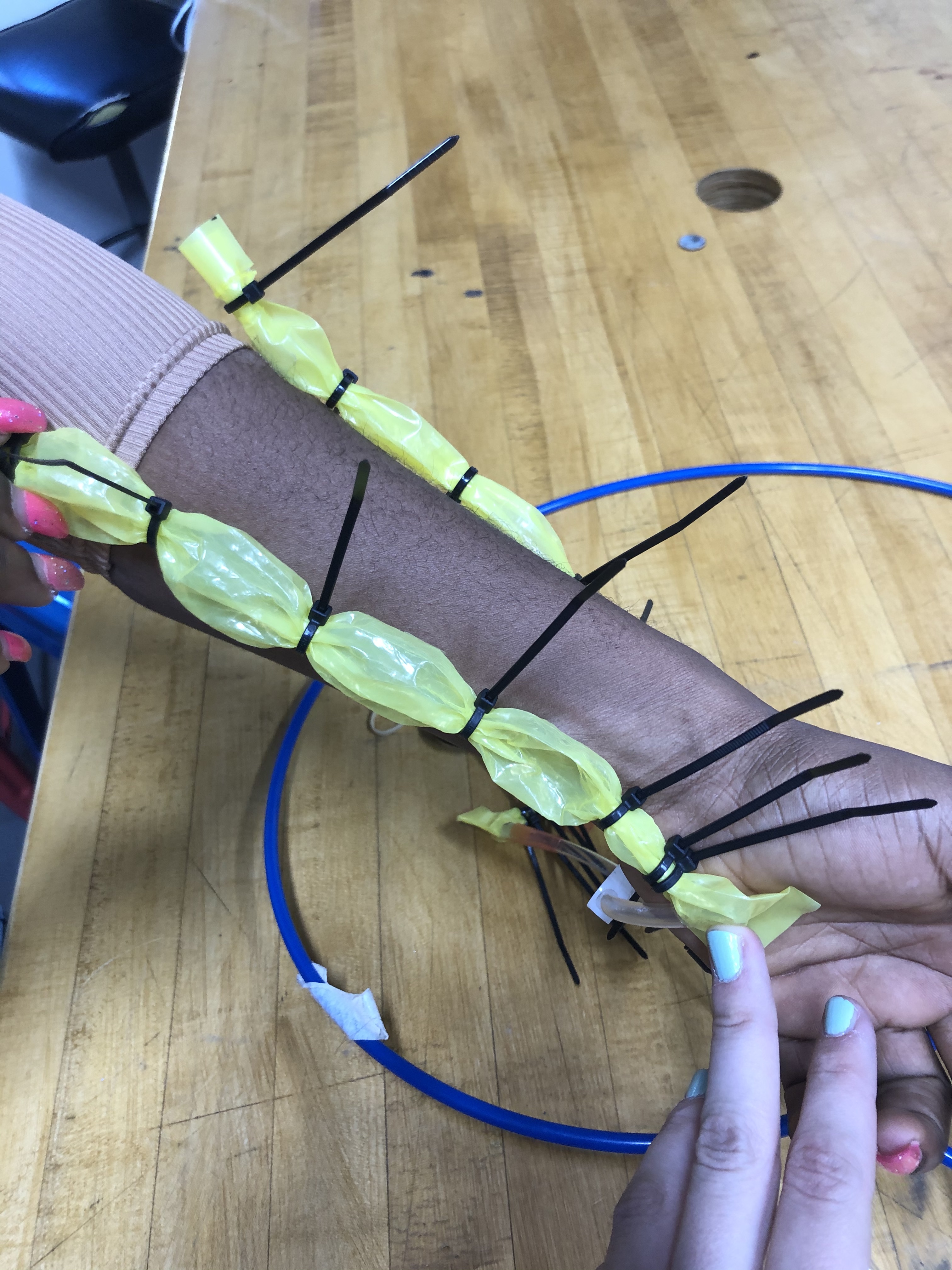
Next, we tried separating the inflatable wrist brace into two partitions using zip ties and found that in this prototype, it was a lot easier to tell which direction the pressure was coming from. We also sketched out a rough draft of what the stencil for the leg “brace” (feedback mechanism) could look like.
As a sensor, we will likely be using a proximity sensor that can sense the physical distance between itself and nearby obstacles. Our Arduino program will get input from this sensor and output to the feedback mechanism. When the input from the sensor gets below a certain threshold, it will cause the appropriate partition of the leg "brace" to inflate and apply pressure to the user's leg to inform them of the obstacle. We will likely use solenoids that we can control the flow of air by applying (or not applying) an electrical current.
Some questions that we will be working on next are:
- We will need to remove the pressure when the obstacle is no longer there. How can we deflate the brace in this case?
- Will we be able to sense obstacles in different directions with just one sensor?
Checkpoint 2
Our goal for Checkpoint 2 was to get the separate components of the system working (that is, the sensor and the soft wearable feedback system), which we achieved. We used the sketch that we created during our work for Checkpoint 1 to create a wearable leg "brace" with three separate inflatable pouches that can be used to provide feedback to the user about which direction to go in by putting pressure on different parts of the leg.
Regarding the nature of this feedback, we conducted a poll with people within our dorms to see what people would think intuitively about the pressure. This was mainly for the pressure on the left and right sides of the leg (as the pressure on the front of the leg will indicate an obstacle in front, telling the user to stop). Out of the 20 people polled, 16 responded that a pressure on the left side of their leg would make them want to go right (and vice versa). Some reasoning supplied was that "it's pushing you the opposite way" and "you put pressure on the left side of a steering wheel to go right".
In terms of the sensor, we connected our proximity sensor to the Hapkit board and wrote an Arduino program that turns on an LED when the proximity drops below a certain threshold. Attach:navigation_sensor.ino.zip