

2023-Group 10

Row Row Row Your Hapkit Setup
Row Row Row Your Hapkit
Project team members: Jose Amador, Emily Wang, Shyan Shokrzadeh, Miyu Kojima
The goal of our project was to simulate the experience of rowing a boat. Using force feedback and a velocity-based dynamics control loop, the user will feel the haptic response that mimics oars pushing through the water based on the input velocity as well as the virtual relative velocities of the water and the boat. Their input will also accurately affect the visual graphics of the boat in the virtual environment.
The resulting product allows the user to control both the speed and direction of a boat via two oars. For both linear movement and rotation, water drag has been simplified to a damping constant to represent viscosity of the water on an object.
On this page... (hide)
Introduction
Since the dawn of time, the traversal of water has been integral to the evolution of women and man. However, in the modern era, society has slowly lost access to this critical physical exercise. The main concern is that the resources required for rowing usually includes a boat, water, or some very large physical contraption. This greatly limits the accessibility of rowing to the growing human population around the world. Sustainability. In order to reawaken the core instincts of humanity, our team has decided to create a new rowing experience for the modern day human. By creating a haptic based virtual rowing environment, we can greatly reduce the physical components required for a revolutionary rowing experience, accurately simulating the experience that our ancestors had when rowing upstream in the historic days.
Background
For our project to feel good, an accurate representation of fluid dynamics needs to be rendered as traditional solid mechanics methods are no longer applicable. Haptic interaction with fluid media needs to account for the fluid motion as forces and torques are applied. Baxter & Lin proposes a series of numerical methods that may be used to compute forces and torques generated by a user�s interaction with an incompressible fluid so that they can be used for haptic feedback [1]. Using a discretized version of the Navier-Stokes equations, viscous drag was calculated while maintaining a low computation cost. This paper provides a framework for computing the feedback torque that should be exerted by our �oars� (the hapkit). While the level of complexity presented in this paper is likely not necessary for our application, it provides useful approximations of fundamental equations as well as methods for force filtering and evaluation of performance.
In order to determine a good dynamics model of the boat, it is necessary to understand the critical forces being applied during rowing, and how that affects the overall movement of the boat. Labb� et al's study showcase have the relative velocities of the boat, oar, and water can be used to derive the pressure drag force and mass forces on the oar during rowing [2]. This allows us to translate the velocity oar or the equivalent user input velocity to a force. From the force, we can then derive an acceleration and velocity as well as a moment that will indicate the boat's movement.
Methods
Hardware design and implementation
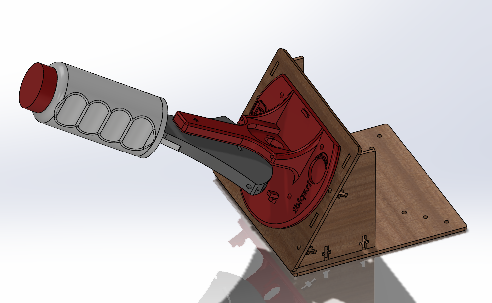
To create our system, we utilized two hapkits, one for each oar. In order to make it more similar to actual rowing motion despite only having one degree of motion, we mounted the hapkit on an angled surface. The handle of the hapkit was also replaced with one that more closely resembled an oar, and included an arcade button that would be used to simulate putting the oar in the water. Below is an image of the CAD for the additional components.
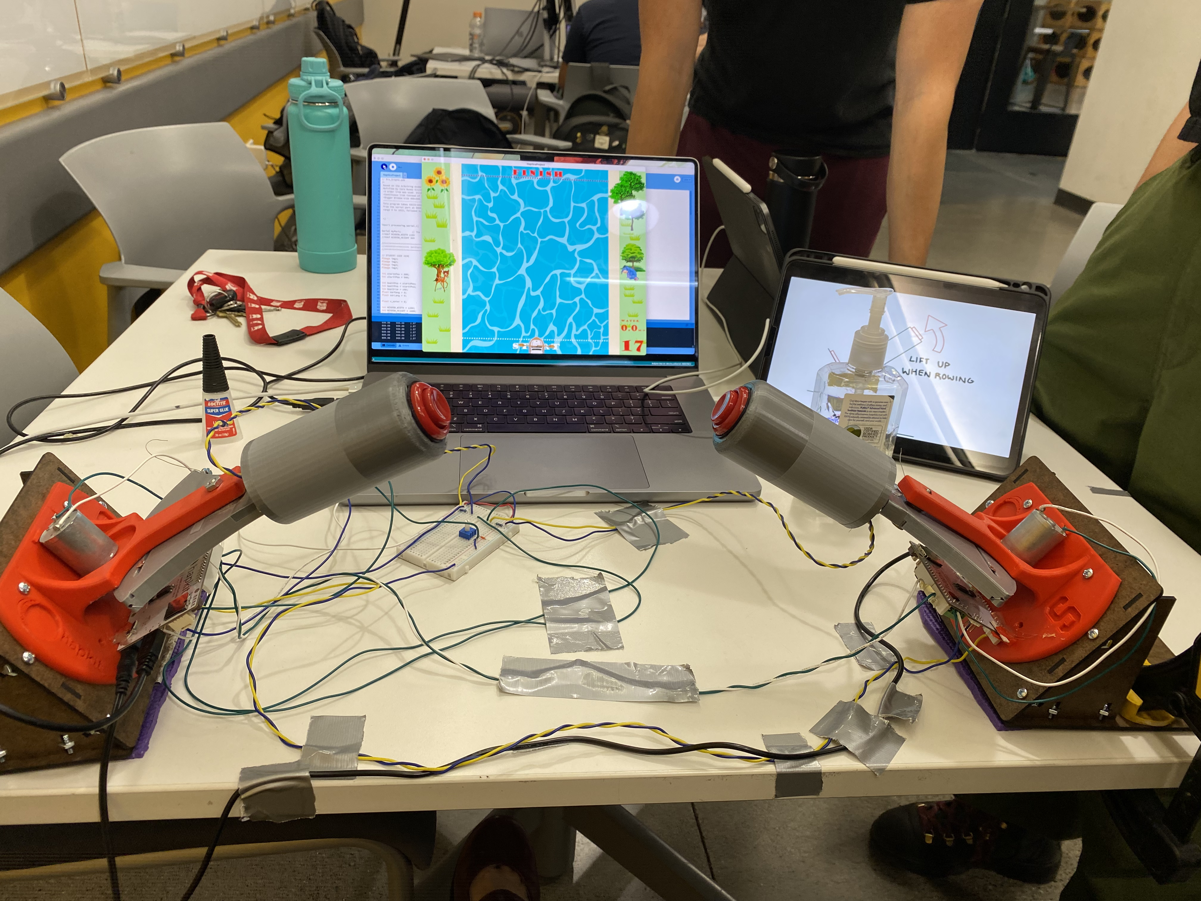
All processing and calculations were done on one Arduino board (left side). The sensor output pin of the right Arduino board was directly connected to the left such that the signal could be read and used in the same program. The pulse-width-modulated (PWM) and directional control signals were also output from the left Arduino board and wired directly into the H-bridge on the right. As such, the microcontroller on the right Arduino is left unused and is bypassed. This method eliminated the latency associated with serial communication and also kept the serial line available for real-time graphical rendering in Processing.
The final result can be seen below:
System analysis and control
Dynamics Model
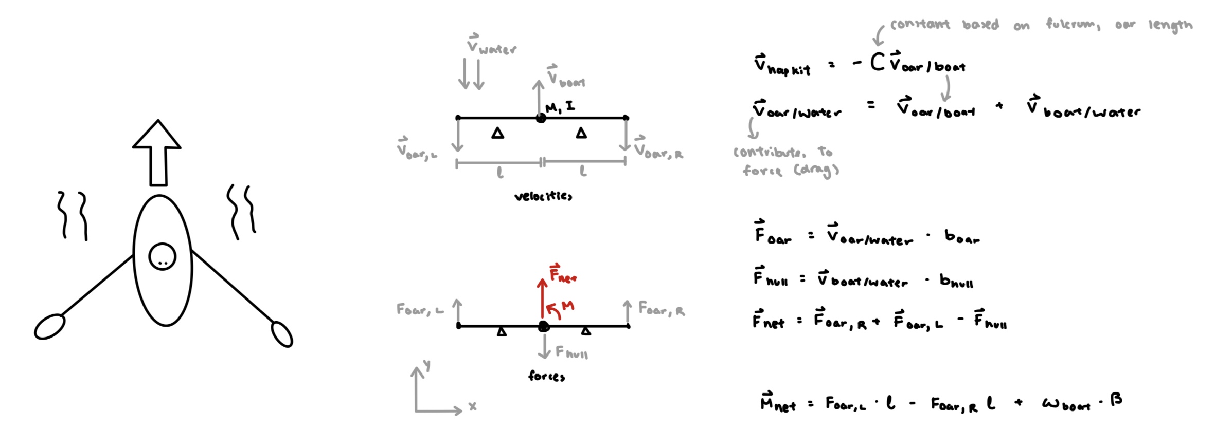
In order to simulate a boat going through the water, we simplified the oar and boat motions, focusing on utilizing damping (water viscosity) as our main force between the user and the virtual environment. We treated the boat as three key points, the oars and the center of mass. As such, we have three potential loads that are applied on the boat that affect it's movement in the global coordinate system. The two oar forces is determined by the user's input velocity to the hapkit, and affect the boats primary linear and rotational movement. In the virtual environment, the water also applies a load on the hull when the user is not moving the oars, which would move the boat as long as there is water velocity.
Arduino Control Loop Logic
The entire control loop can be seen below with step by step descriptions of implementation following.
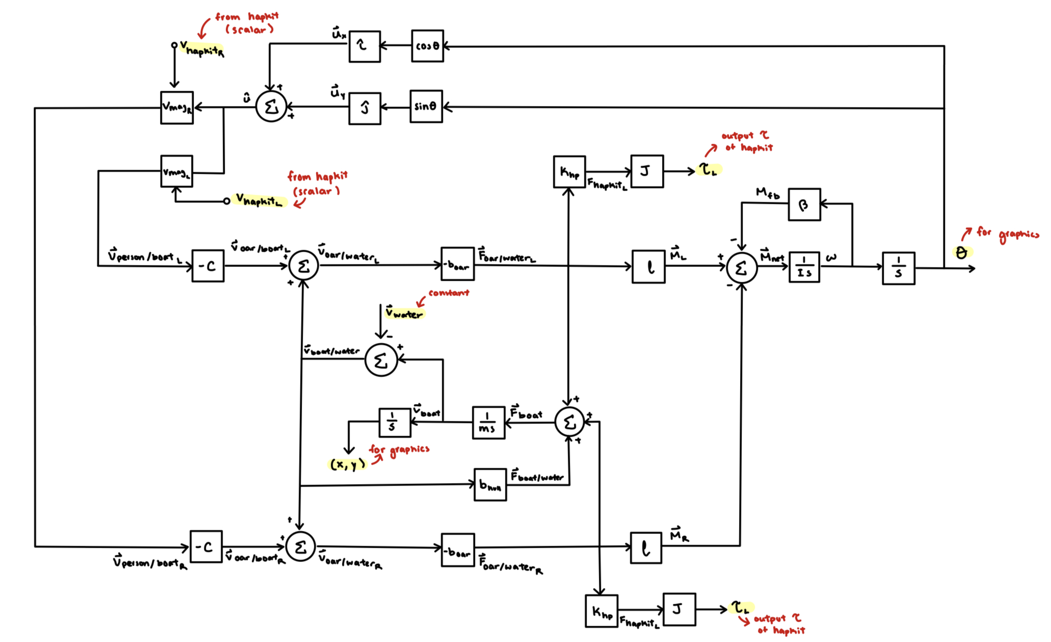
Our control system starts with the user input via the hapkit. This is our input velocity. We vectorize the direction of this speed by utilzing the angle of the virtual boat, in order to calculate the velocity of the person's motion with respect to the boat. For the sake of simplification, we assume the oars is always moving in parallel with the boat.
The velocity of the person with respect to the boat is then scaled by a constant that's supposed to mimic the ratio of the oar length with respect to the fulcrum length. By reversing the direction, this then gives us the velocity of the oar with respect to the boat.
In order to get the velocity of the oar with respect to the water, we add the velocity of the boat with respect to the water to the velocity of the oar with respect to the boat. Since the velocity of the boat is dependent on prior loops, this turns our system into a feedback loop.
The force of the oar on the water can then be calculated by multiplying the velocity of the oar with respect to the water with a damping constant that simplifies the drag forces on the oar.
This force is than translate to the hapkit using the Jacobian. In order to stabilize and improve the realism our system, we had to add another scaling factor to get the actual Force and Torque for the hapkit.
This is done for both the left and right hapkits.
The passive force of the water on the boat is then also calculated from the velocity of the boat with respect to the water. Like for the oars, we use another damping constant to represent drag forces.
The forces from the oars and the hull are then summed top get the net force from the boat on the water in order to calculate an acceleration in the global frame.
The acceleration is then integrated to find the velocity of the boat with respect to the water using a discrete trapezoidal integration. As mentioned before, this is then fed back in to the next loop.
In order to determine the actual new position, the velocity is once again integrated (using the discrete trapezoidal method).
For rotation, moments are required to calculate the angular movement of the boat. To calculate the moment on the boat, we multiply the Force on each oar by a constant representing the length of the oar, and then sum it to get a total moment. The drag force moment on the boat is also subtracted to create another feedback loop.
This moment is then used to calculate the angular acceleration on the boat and integrated to find the angular velocity. In order to have more realistic rotation, rotational damping is used to simulate water viscosity when turning.
Finally, the angular velocity of the boat can be used to find the angular position of the boat which is used for the next loop.
Validation and Tuning
For implementation there were a few key parameters that we had to tune in order to create a stable and realistic system.
The final parameters are as follows:
Virtual physical property parameters such as mboat and Iboat had the most effect on the actual physical movement of the boat in the virtual environment. These were tuned by targeting a specific realistic virtual velocity that we wanted with normal player behavior.
The various damping coefficients had the most affect on the stability of the system itself, but had to be adjusted in parallel with the aforementioned constants. Specifically bwater,oar and bwater,hull had the most effect on the system. We found when the damping was really large, it was easy for the system to go unstable, most likely due to noise amplification of the magnetic sensors. However, if b was too small we wouldn't get realistic values for our boat movements in the virtual environment.
Additionally, we used an Infinite Impulse Response Filter to try to smooth out the input velocity and added a lower and upper deadband.
Overall, we were able to tune our system relatively well. However, the mechanical robustness of the hapkits and magnetic sensor prevented us from getting extremely fluid haptic response. The drifting of the magnetoresistive sensor led to the oar to drift in the graphics and the mechanical imperfections in the mounting led to noise and vibrations that we were unable to completely filter out.
Demonstration / application
Here is a link to our project during demo day: Demo Day Video
Results
Overall, we created a fun simulation with realistic dynamics. During the open house, the transportation of our project to the demo space did lead to some mechanical problems as we later found out that the hapkit mount was extremely loose leading to a lot of the vibration getting translated to chatter that felt extremely unstable (specifically more on one side). However, we were later able to fix this by replacing the mount with a nut for the second portion of the open house.
On demonstration day, most people could "beat" the game in their second or third try as they had gotten used to the rhythm required to move the oars (training effect). The motion of the oars was a bit confusing to some because it was reversed from the normal motion (because usually, people sit backward), but we wanted the user to be able to see the visuals and have the motion match. It also seemed like a lot of people seemed to turn left consistently. At first, we thought this might be a tuning or sensor issue, but later realized it was due to most people being right-handed and have higher overall velocity/control over the right oar since the force is highly sensitive to input velocity. Many people commented that the haptic response made it feel more difficult but also more realistic, which makes sense because rowing is supposed to be physically strenuous.
Most people who were somewhat familiar with hapkits did a lot more exploration regarding the details of our dynamics system, such as noticing that you could still feel the water when the boat was drifting/braking, or how the movement of one oar affected the motion of the boat, which thereby affected the forces felt on the other oar.
Conclusively, we are pleased with the performance of the device (particularly with the simulation realism) but would like to make mechanical and electrical improvements to reduce the vibrational instability. This would clarify the haptic response and improve the overall experience for the user.
Future Work
The main improvement that can be done to our project is likely to make it more mechanically robust. A lot of our instabilities were actually a result of fatigue and failure in the hapkits, as well as noise and drift in the magnetic sensor. By improving the hapkit design with better tolerances and material selection, and by using better sensors/motors, we could create a more realistic and stable experience for the user. By departing from the hapkits, we would also be able to potentially add another degree of freedom, such that the user could actually physically remove their oar from the "water," as the button did seem to make the timing rhythm difficult for some users. Additionally, this would make the act of dipping the oar more continuous (variation in force output) as opposed to the oar suddenly appearing underwater in a discrete manner.
For the dynamics model, the next steps would be to make our environment more complex, adding features such as collisions and circular water flow (i.e. whirlpools), and have this reflect haptically. For collisions, we could simulate how the oars would interact with riverbanks and rocks, as well as the impulse generated from the boat colliding with an object. We could also work to make our drag force more complex through a more realistic fluid flow simulation about the oar. This is also the case for the hull, since that is currently modeled as a point mass. Notably, the water is currently unaffected by the forces applied by the hull and oars but would, in reality, have complex dynamic behavior. However, it is questionable how much of a notable impact this would have on the haptic experience and may be a purely visual phenomenon.
We are predominantly interested in testing our device's realism with respect to the true experience of rowing in water. This would first require the aforementioned updates to add realism and maintain consistent/stable results. Quantitatively, we would track the rowing motion (specifically that of the arms) that users are inclined to use with our device and analyze its deviation from real rowing (forces applied, velocity of various body parts, posture and motion path). Qualitatively, we can evaluate the haptic quality and experience via Likert scale questionnaires and other surveying methods. It would be reasonable to have both experienced and novice rowers conduct the comparison.
For even further expansion, it may be of value to evaluate the rowing simulator as a means to help people improve their rowing capabilities. This would require further improvements to further align the simulation with the real experience and then long term studies in comparison with existing training methods over a long period of time.
Files
All file links can be found below:
References
Baxter, W., & Lin, M. C. (2004, January). Haptic interaction with Fluid Media. http://gamma.cs.unc.edu/hapticfluid/Baxter-FluidHaptics-GI04.pdf
Labb�, R., Boucher, J.-P., Clanet, C., & Benzaquen, M. (2019). Physics of rowing oars. New Journal of Physics, 21(9), 093050. https://doi.org/10.1088/1367-2630/ab4226
Appendix: Project Checkpoints
Checkpoint 1
Dear Diary,
For the first checkpoint, our team met to determine the physics model we would be using to create the virtual environment with the row boat to derive the corresponding haptics response. To do so, we simplified the rowboat as a point mass with 2 point masses connected perpendicular to the axis of movement to represent the oars. By doing this we can simplify the velocity vector of the oar and ignore additional complications from angular positioning.
We then utilized the relationship between the relative velocities of the person (hapkit), oars, boat, and water to determine the simulated force on the oars. This force is found using a damping constant to simulate the drag force. The two oars are then summed into a net force of which the acceleration and velocity of the both with respect to the water can be found and fed back into the loop for the subsequent calculations.
For visual graphics, the boat requires an x, y, and angle to be fully defined. Position coordinates can be found by integrating the already known velocity vector, while angle is defined by calculating a moment from the independent oar forces and integrated. For additional realism, an angular damping coefficient is added into another feedback loop for rotation. We have also assumed that the water flow is unaffected by the presence of the boat (i.e., the force on the water by the boat is zero, thus its velocity is constant).
Below is the complete block diagram showing how to derive components for both haptic feedback and visual representation.
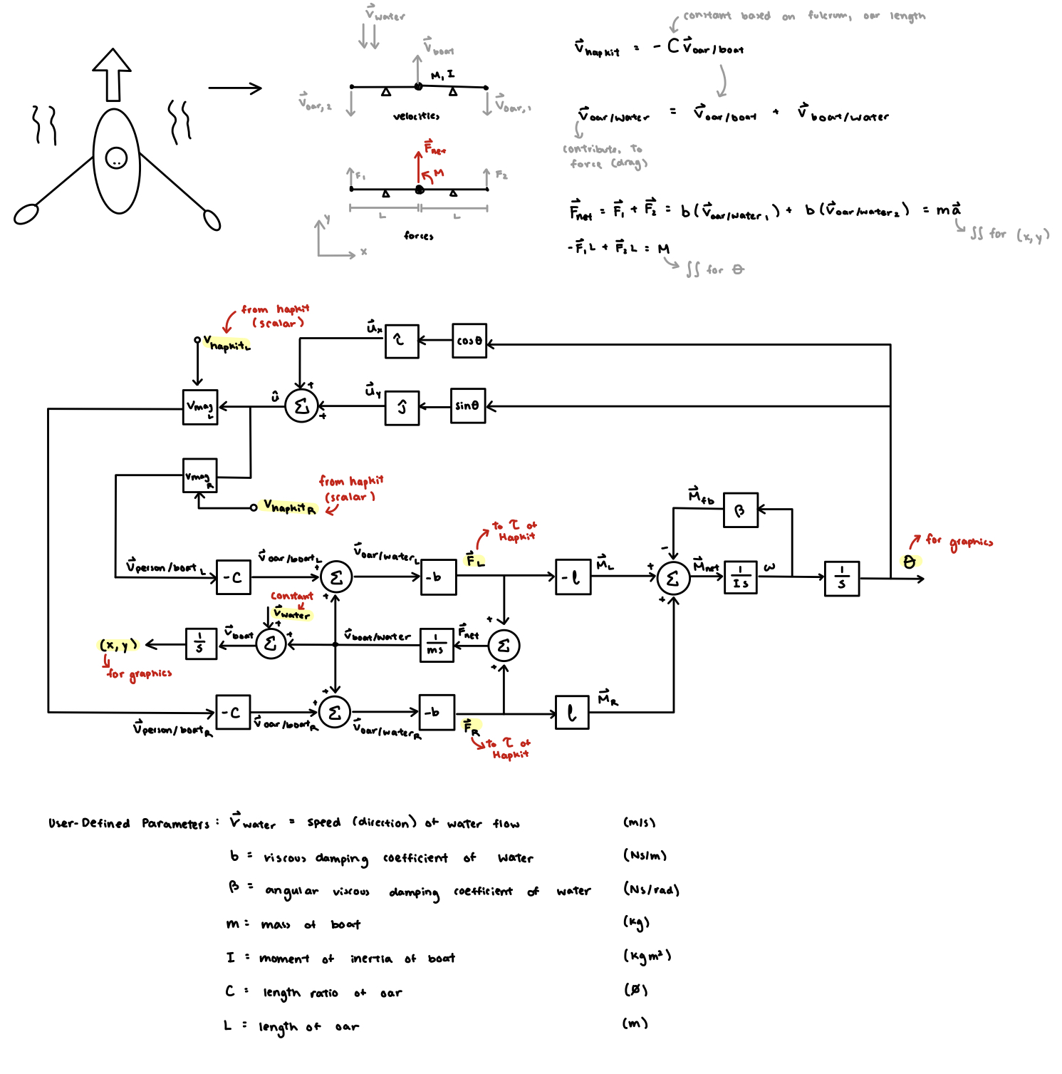
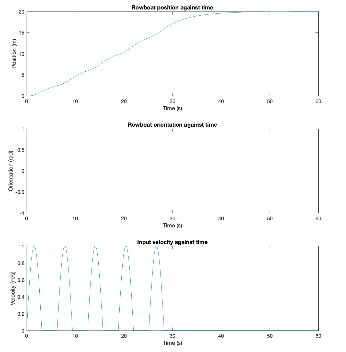
From this block diagram, we created a rudimentary Simulink model to sanity check our system within a single axis and a saturated sinusoidal input.
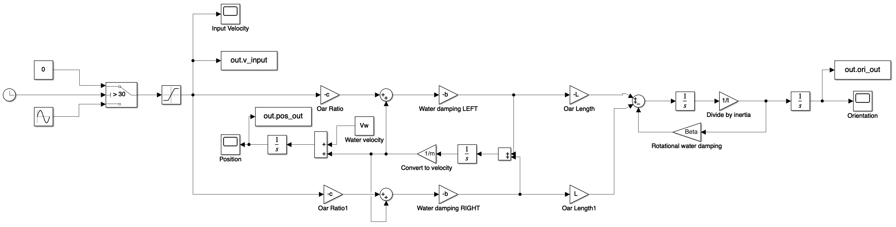
The results generated by the model helped us debug sign issues. We believe the final results to be reasonable within a single axis, as the boat starts/stops with the presence/absence of rowing velocity. Additionally, orientation remains at zero due to the equal left and right oar velocities.
From the model, we then wrote some initial code for a single Hapkit (left), simplifying the logic temporarily to only the y-axis.
The file can be found here: Left Oar (Leader) Arduino Code, checkpoint 1
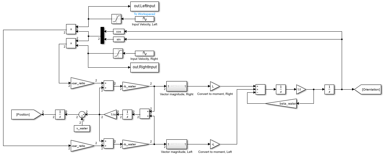
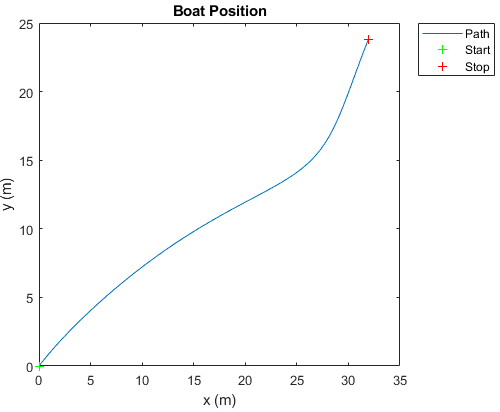
Additionally, the Simulink model was later expanded to vector form to completely simulate the system in x-y-theta coordinates.
This result shows the boat path when the left stroke is slightly stronger than the right at the same rowing frequency (~1.59 Hz):
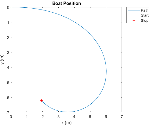
This result shows the boat path when the left stroke is slightly stronger than the right at the same rowing frequency but with a 45 degree river current.
These results have given us confidence in our model. Thus we can proceed with a complete version of the code in 2-D space.
Checkpoint 2
Dear Diary,
For checkpoint 2, our teams goal was to start transitioning to the actual hapkits and processing. We were able to get our initial model into one hapkit with relatively good response. This required some modifications to our initial code and a lot of tuning of the many parameters that are shown in our checkpoint 1 block diagram, in order to ensure stability and realism. We noticed that our angle feedback loop led to a lot of instabilities for some reason, so it is temporarily removed as we got y position working with the boat.
In addition, we also added the button feature, that would allow the user to determine when their oar is in the water depending on if the button is being pressed. This arduino code was then connected with processing code so that we would have graphic visuals where the boat move forward as you row!
The new arduino code can be found here: Left Oar (Leader) Arduino Code, checkpoint 2
And the processing code can be found here:Processing Code, checkpoint 2