

2023-Group 4
2 Degree of Freedom Assistive Drawing Device
Project team member(s): Lisa Gunnarsson, Rio Hall-Zazueta, Sydney Richardson, & Xander Sahin

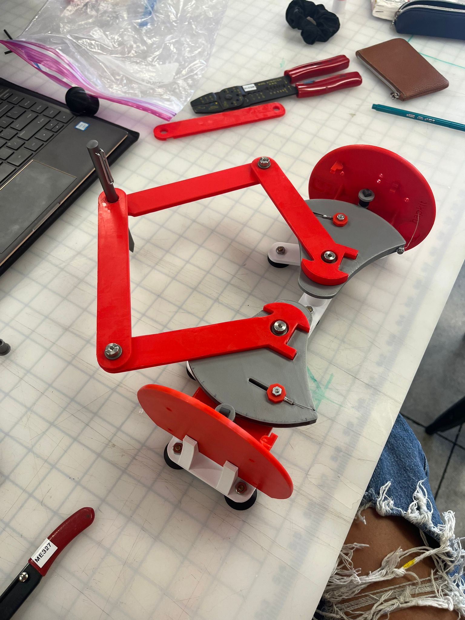
Caption:
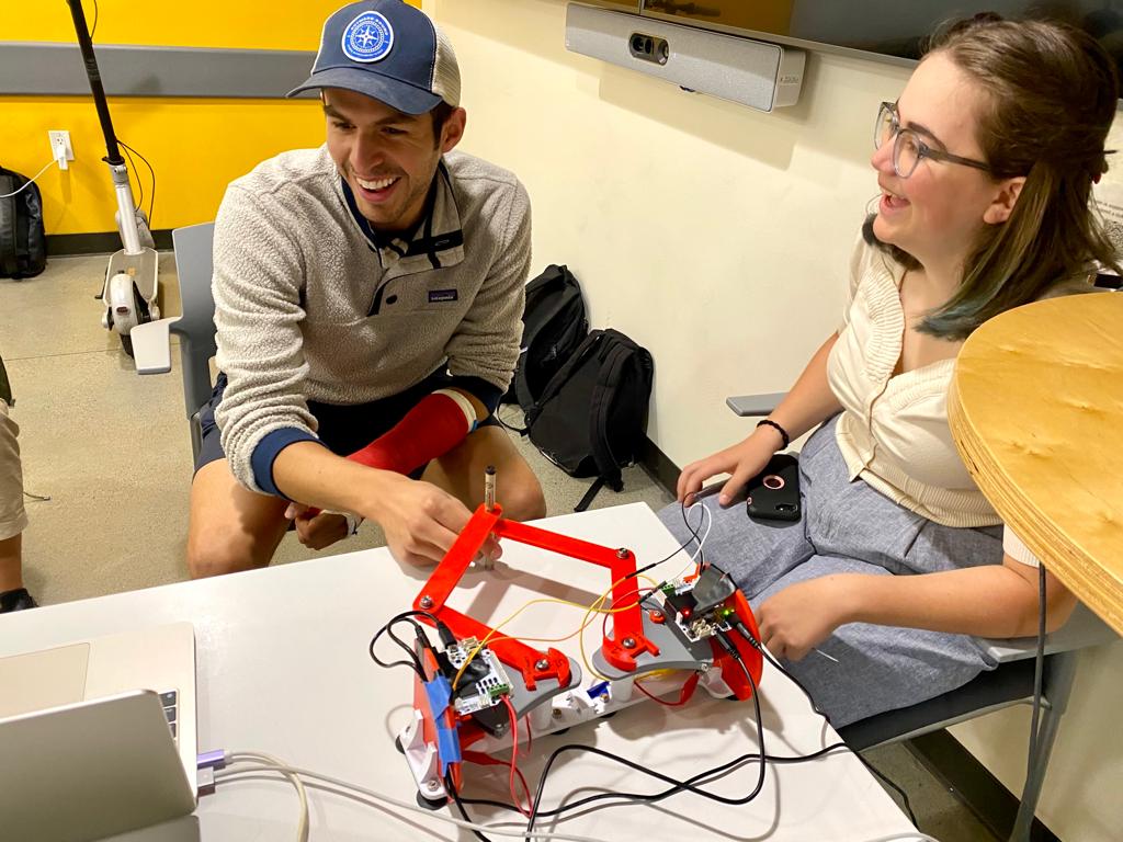
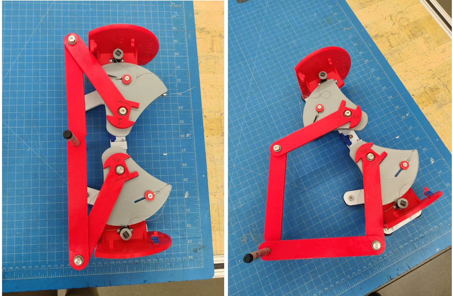
Team with the final assistive drawing device at the
Haptics Open House
We implemented a 2 degree-of-freedom haptic device (pantograph) with the goal of drawing/writing assistance. This pantograph will serve as a virtual �outline� of a drawing/specific pattern we want the user to follow. This project sought to implement the initial goal of creating the physical device and designing the necessary algorithms to give haptic force feedback alongside visual feedback to the user when trying to outline a specific pattern (in our case a circle). Our device aims to help anyone who may face difficulty in drawing/writing in a stable and controlled manner such as children or physically disabled persons. With the force feedback individuals can better learn to trace objects as a form of motor skill development. The study performed comparing user performance tracing a circle with only visual feedback in comparison with haptic and visual feedback showed the average position error from the true circle is 2.24 times higher without force feedback than with force feedback.
On this page... (hide)
Introduction
The motivation for this project is to assist individual�s learning their motor control skills applied to drawing. A challenge for children, disabled people, or anyone learning to write/draw consistently is the control that comes with drawing say a line. The educational objectives for our project is to assist in drawing controlled lines (in our case a circle). We have chosen a two degree-of-freedom haptic device (a pantograph) to apply forces to a user trying to draw a circle to encourage precise drawing strokes.
Background
Previous studies [1,2,3] have examined the efficacy of a visuo-haptic device as a teaching method to improve the fluency of handwriting of kindergarten students. The control group of study [1] was instructed with classical methods, while the experimental group used the Telemaque visuo-haptic device. The Telemaque is a �force-feedback programmable pen.� They found that the Telemaque-based intervention produced greater improvement in the recorded metrics. Study [2] saw that when tested on able bodied users, the haptic writing aid device (they developed a control algorithm and graphic user interface) successfully controlled the user hand motion through the writing process. The outcomes of these studies show that a functioning and robust design of a writing assisting device can be developed, and our team will take inspiration from the work of these papers. We will draw inspiration from the error study performed in study [3]. This study used the omni touch device alongside a pantograph device in order to assist in drawing/hatching/cutting tasks. The study performed would have the haptic device turned �off� (draw a circle 50 cm in diameter) then �on� (draw a circle 25 cm in diameter that mapped to a circle 50 cm in diameter), then analyzed the error of the drawing by the distance of the drawn line from the actual circle guide. Our own project can take heavy inspiration from the study performed.
Methods
Hardware design and implementation
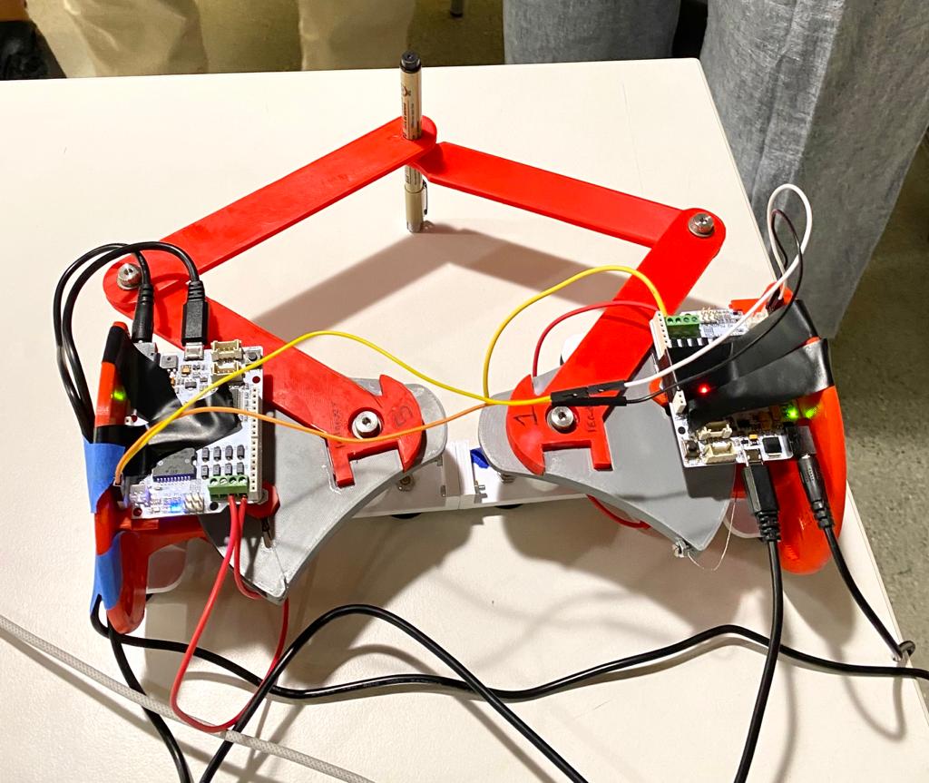
We referenced the Two-Degree-of-Freedom Devices page (https://hapkit.stanford.edu/twoDOF.html) on the Hapkit resources and selected to use the Graphkit design as it closely matches the requirements and use-case of our design. We 3D printed and purchased the additional necessary components (beyond two Hapkits) in Room 36 and assembled the links according to the instructions to form a pantograph device. One modification we made was to cutting away part of the Hapkit bases to increase the size of the workspace; the interference between the Hapkit bases and the links connected to the handles put a restriction on the movement of the stylus.
Two Hapkit boards and motors were attached to the original Hapkits. The boards were used to compute the stylus location using MR sensors, and the motors were used to output the rendered force felt by the user.
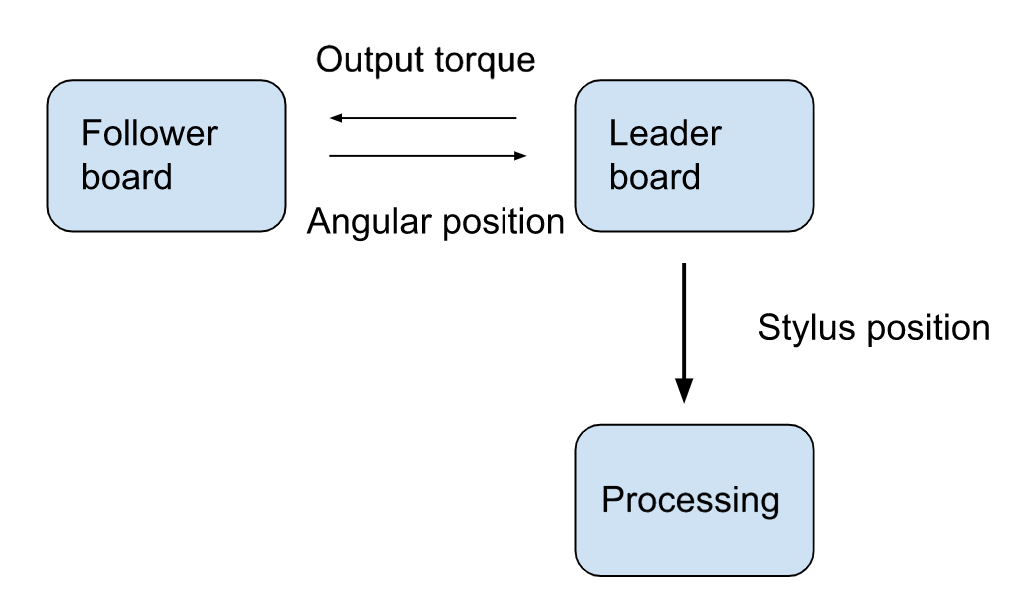
System communication, control and rendering:
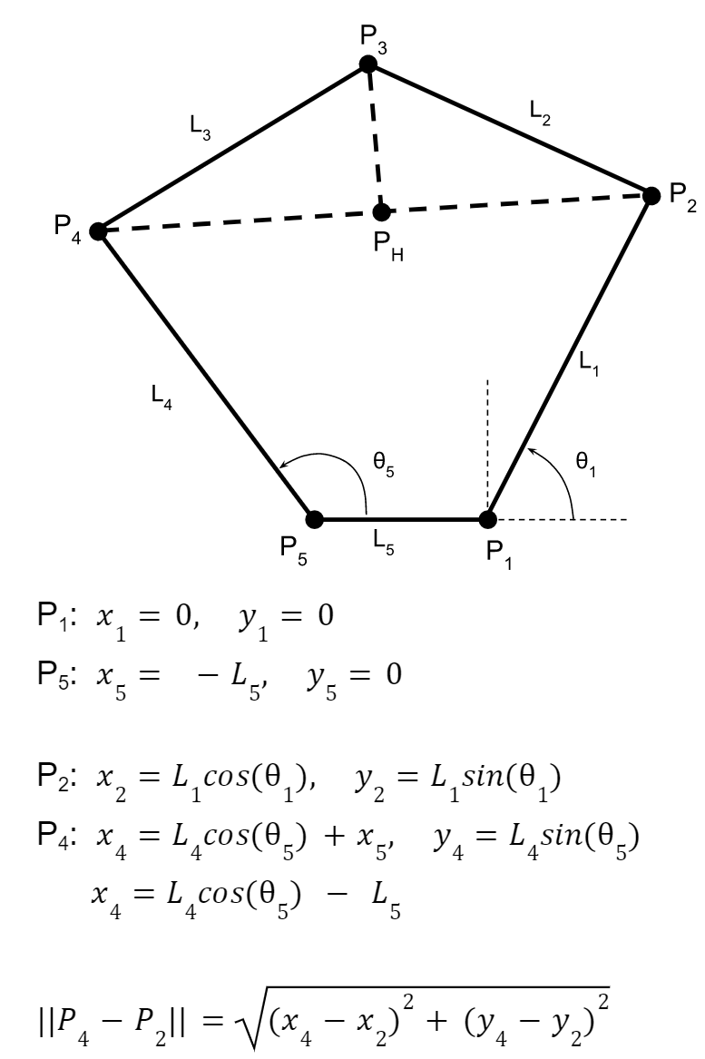
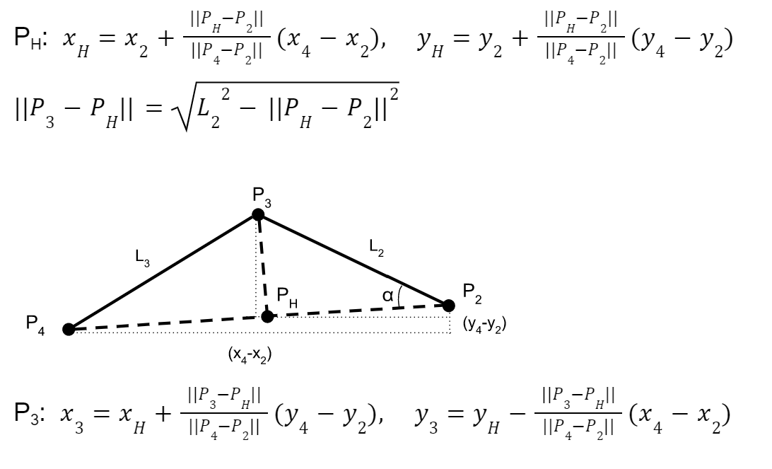
The leader board computes the stylus location with the equations described in the appendix (checkpoint 2), and renders the torques for haptic feedback for the user to follow a circle. The stylus position is computed with the forward kinematics of the pantograph [4] [see appendix for additional detail]. Forces were applied to the user if they left the circle by calculating the distance and direction to the nearest point on the circle and applying a proportional force. The radius for applying a force was set slightly inside the circle, so that the user feels the force feedback before they are significantly outside the circle. These desired Cartesian force magnitudes are converted to motor torques using the dynamics of the device and a Jacobian matrix with key constants to appropriately scale the forces to find the required torques using the relationship tau = JTF. We used the Jacobian function from 2012 ME 327 Project: A Planar 2-DOF Haptic Device for Exploring Gravitational Fields (http://charm.stanford.edu/ME327/JaredAndSam).
In order to allow communication of the stylus location to Processing via Arduino�s Serial communication, I2C communication channel had to be set up to exchange information between the two boards. The leader requests the handle angle from the follower board, and sends back the torque value for the follower motor output. Since these values are both floats, the values had to be converted to strings and sent byte by byte, then reconverted into a float value.
Demonstration / application
We demonstrated this device at the ME327 open house on June 6th. The device performed as expected providing its virtual stencil and we enjoyed seeing user's surprised responses when they could notice the forces being applied. The demo ended up being quick as wanted as users could simply sit down and start using the device. Many users would draw a few circles and get familiar with the space then proceed to color in the circle.
Study and evaluation process
In our study we compared user performance tracing a circle with only visual feedback in comparison with haptic and visual feedback. Participants were asked to trace the circle pattern we rendered on the device with their non-dominant hand. We chose to have participants use their non-dominant hand to simulate a user still learning to accurately trace or draw. We first asked participants to trace the circle to the best of their ability with the motors disconnected from the device, referencing only the graphics for visual feedback. We then asked participants to trace the circle again, this time with force feedback from the device. In each trial we recorded the distance between the user and the closest point on the circle for each time step.
Results
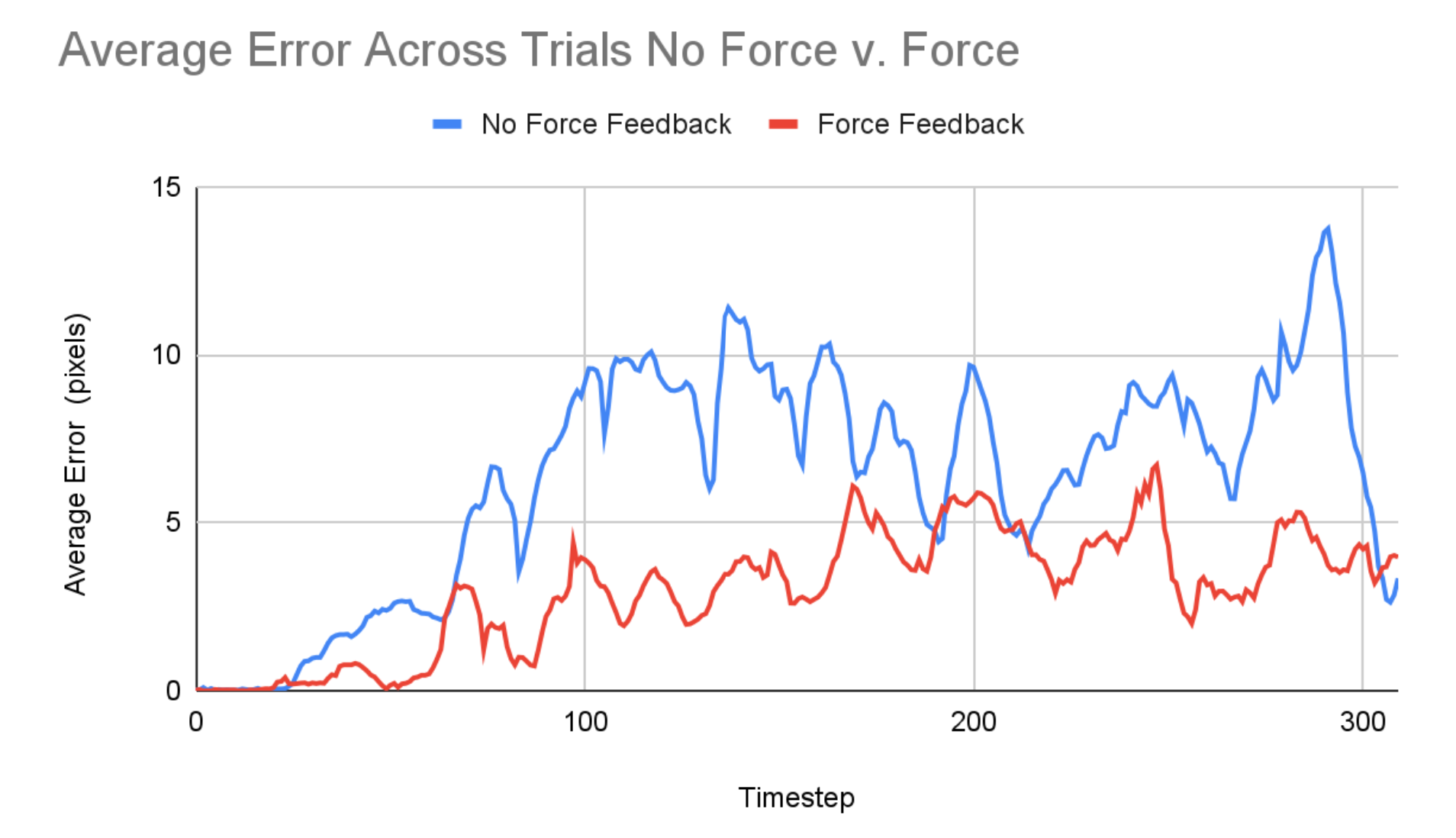
Based on trials of our experiment with five different participants, we found that the average position error from the true circle is 2.24 times higher without force feedback compared with the average position error with force feedback. The plot below shows the average performance with and without force feedback across the five trials. This provides some evidence that force feedback results in less error in the shape drawn; although to confirm this result we would want to run the experiment on a larger group with double reversal and randomized condition order to mitigate impacts of learning.
One other piece of feedback we received was that the force feedback allowed users to draw more quickly and effortlessly, as opposed to slowly and meticulously tracing the shape based on visual feedback. This is especially promising qualitative feedback for the use of this device to improve drawing or writing ability because, as noted in Palluel-Germain et al., it is important that one masters the ability to recreate the dynamic feeling of a pattern, not just the ability to recreate the positions, in order to recreate it efficiently without guidance.
Future Work
Our device is a low fidelity implementation of the drawing aid concept and could be improved for more effective use by those learning or relearning to draw. Adjusting the linkages and housing to increase the workspace would provide more freedom for diverse drawing or handwriting exercises which do not need to be recentered for each new shape or trial. Additionally, the tolerances between joints and support between the drive motors and the drawing tool could be improved to achieve a smoother user experience. Higher torque, better resolution motors would also allow for more rigid and smooth virtual boundaries without instabilities. Next, the training algorithms could also be further developed and diversified beyond tracing a circle. More complex shapes, lines, and handwriting tasks could be implemented. Finally, to make more concrete conclusions about the effectiveness of haptic force devices as a teaching tool, more data should be collected for unassisted drawing after training to see if there is long-term motor coordination improvement as a result of the drawing aid.
Acknowledgments
Thank you to all the CAs (especially Dane and Connor for lots of troubleshooting!) and Allison for all the help on the project!
Files
Arduino Leader code: Attach:ArduinoCodeFollowerGraphkit2023.txt
Arduino Follower code: Attach:ArduinoCodeLeaderGraphkit2023.txt
Processing code: Attach:ProcessingCodeGraphkit2023.txt
References
1) R. Palluel-Germain, F. Bara, A. H. de Boisferon, B. Hennion, P. Gouagout and E. Gentaz, "A Visuo-Haptic Device - Telemaque - Increases Kindergarten Children's Handwriting Acquisition," Second Joint EuroHaptics Conference and Symposium on Haptic Interfaces for Virtual Environment and Teleoperator Systems (WHC'07), Tsukuba, Japan, 2007, pp. 72-77, doi: 10.1109/WHC.2007.13. https://ieeexplore.ieee.org/abstract/document/4145154
2) J. Mullins, C. Mawson and S. Nahavandi, "Haptic handwriting aid for training and rehabilitation," 2005 IEEE International Conference on Systems, Man and Cybernetics, Waikoloa, HI, USA, 2005, pp. 2690-2694 Vol. 3, doi: 10.1109/ICSMC.2005.1571556.
3) Covarrubias et al., �Pantograph Mechanism for Increasing the Working Area in a Haptic Guidance Device for Sketching, Hatching and Cutting Tasks.� pp. 1377-1384. ASME. 2012. https://doi.org/10.1115/DETC2012-70800
4) �Design and Control of a Pantograph Robot.� Design and Control of a Pantograph Robot - Northwestern Mechatronics Wiki, hades.mech.northwestern.edu/index.php/Design_and_Control_of_a_Pantograph_Robot
Appendix: Project Checkpoints
Checkpoint 1
Our main goal for the first checkpoint was to manufacture and assemble all the necessary hardware for our device. We referenced the Two-Degree-of-Freedom Devices page on the Hapkit resources and selected to use the Graphkit design as it closely matches the requirements and use-case of our design. We 3D printed and purchased the additional necessary components (beyond two Hapkits) in Room 36 and assembled the links according to the instructions to form a pantograph device. One modification we may make is to cut away part of the Hapkit base to give a larger workspace. Currently the interference between the Hapkit bases and the links connected to the handles puts a restriction on the movement of the stylus, creating a small, wedge-shaped workspace.
In addition to assembling our hardware we set up a GitHub repository to easily share code between team members. We also examined the code of past projects using similar devices to verify our understanding of determining the position and force outputs for the pantograph layout. We generated a list of functions to implement (see below) in order to carry out our study and plan to use the teleoperation template code as a reference for implementing the sensor reading, motor control, and board-to-board communication.
Functions:
// compute the angle of the first 2 link arms (attached to the base) from the raw encoder value
encoder_to_angle(upddatedPos) → theta
// compute the 2D position of the stylus from the 2 base link angles
kinematics(theta1, theta2) → x, y
// Render force vector from the position of the stylus according to the shape of the drawing
render(x, y) → vec(force)
// Compute torque of the 2 motors from the force vector
force_to_torques(vec(force) → torque1, torque2
Checkpoint 2
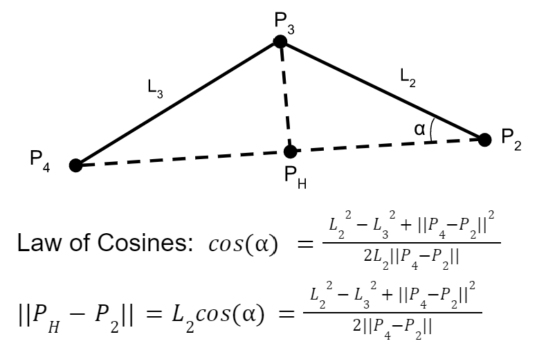
Forward Kinematics:
Control scheme:
The leader board computes the stylus location with the equation described in the section above and renders the forces and torques for haptic feedback for the user to follow a circle. In order to communicate the stylus location to Processing, another communication channel had to be set up to exchange information between the two boards. The leader requests the handle angle from the follower board and sends back its torque value for the motor output. The force rendering has been coded up but not tested yet; we will work on that in the next few days.
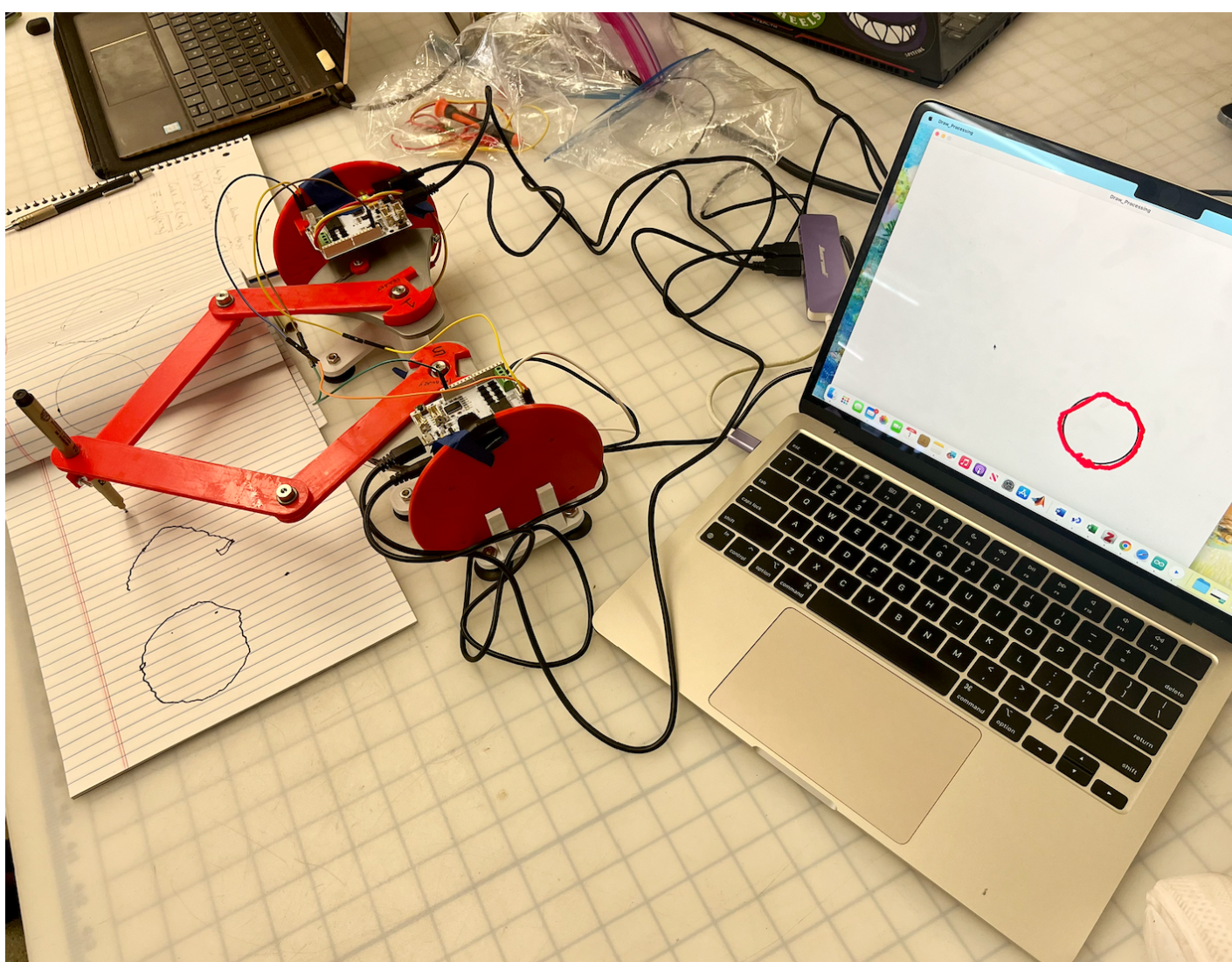
Processing graphics:
We were able to achieve an okay amount of traceability from the pantograph to processing. The structure of the processing code is correct in its ability to display an input x and y position, however, this position needs tuning. Once we start applying forces the processing graphics will be fine tuned for the final result. As seen in the picture attached, the processing rather accurately displays the drawn circle, albeit shaky. Our goal is to reduce this shakiness by addressing the mechanical issues described below.
Increased workspace:
The workspace for the device was increased by cutting a part of the bases of the original hapkits.
The accuracy of the stylus location tracking is not as high as we wished for, most likely due to the mechanics of the pantograph (friction) and due to hapkit angle measurement drift.
What to do next:
Focus on achieving the necessary forces to be applied to the user to trace circle shape accurately and attempt to get the mechanics of the device as smooth as possible.