

Agharese Townshend Gruebele
Camille, Alex, Nathaniel [left to right]
Team Re-SWOLE with device
Re-SWOLE: Rehabilitation via Skin-stretch Wearable Operating on Lower Extremity
Project team member(s): Nathaniel Agharese, Alex Gruebele, and Camille Townshend
Summary
To recover from physical injury, a consistent rehabilitation exercise regime is necessary. Rehabilitation exercises often require precise movements to function as intended, and without the live guidance of a physical therapist, form can suffer. Our goal is to use skin-stretch and vibration haptic feedback to guide rehabilitation form in patients with knee injuries, to improve their recovery outcomes.
On this page... (hide)
Introduction
To recover from physical injury, a consistent rehabilitation exercise regime is necessary [1]. Physical therapists are crucial in formulating specific exercise routines for patients and keeping patients on track. In addition to sessions with physical therapists, patients usually need to perform many of the exercises on their own time. Rehabilitation exercises often require precise movements to function as intended [2], and without the live guidance of a therapist, form can suffer [3]. Our goal is to use skin-stretch and vibration haptic feedback to guide rehabilitation form in patients with knee injuries, to improve recovery outcome. We aim to learn how the combination of the two haptic feedback modalities affects users’ accuracy in reaching a set target angle.
Background
In the case of rehabilitation exercises for posterior cruciate injuries, isokinetic extension of the knee to less than 70 degrees (110 degrees when a fully extended knee is defined as 180 degrees) is considered to be safe, however “deep squats should be avoided until healing is well-advanced.” [4] This motivates the purpose of Re-SWOLE as a device for safely guiding a user through their rehabilitation exercises. In addition, for our experiments we will choose the clinically relevant 110 degree knee angle as the target for squatting.
With regards to haptics, skin-stretch has been shown to be effective in guiding and even altering proprioception as it activates both slow-acting and fast-acting mechanoreceptors [5]. Another study found that skin stretch provides a better proprioceptive sensory experience than vibration due to its higher analog resolution and due to its intuitive mapping for position information [6]. Few studies have been done on analog skin-stretch feedback in lower extremities, however one has looked into a binary skin-stretch feedback on the lower extremity to improve balance in lower-limb amputees by indicating foot position throughout a user’s gait [7]. In Re-SWOLE, skin-stretch is used to guide a user’s knee flexion angle throughout a squat. In addition to its directional guidance, skin-stretch has the potential to simulate proprioception of a slightly more or less flexed knee angle to the user. A study similarly found that skin-stretch on the wrist and forearm had the potential to simulate wrist proprioception for hand amputees [8]. This alteration of proprioception for knee angle may encourage a corrective reaction by the user in the desired direction.
Since vibration has been shown to have lower resolution than skin-stretch feedback [6], it is better suited for event-based, binary cues. In one study, vibration feedback was used to communicate varying levels of hand opening [9]. Correct hand positioning was only achieved 30-50% of the time. This proves that using vibration in an analog manner to communicate a signal range does not result in a high resolution haptic feedback. Vibration feedback is also widely used in alerting phone users to notifications, which are inherently event-based. In Re-SWOLE, vibration is used to cue the user when they have reached the full intended range of motion.
Methods
Hardware design and implementation
The device we designed is worn on the left knee, and gives the user two modalities of haptic cues as they perform a squat to a prescribed angle. To don it, the user puts their foot through the compression sleeve and pulls it up to their knee, where it is secured with a strap. The user starts the exercise standing (Figure X), and feels a skin stretch cue on their thigh pointing downwards, urging them to bend their knee and initiate a squat. They follow this cue (the magnitude of which starts to decrease as they approach the target angle) until they have reached the target angle. At this point, they no longer feel skin stretch, and receive a vibration cue (Figure X: b). If they go any further than the target (Figure X: C), the vibration cue is lost, but a skin stretch cue in the opposite (upward) direction is felt, urging them to extend their knee and move upward. This extra stretch also simulates proprioceptive feedback felt during a deeper squat.
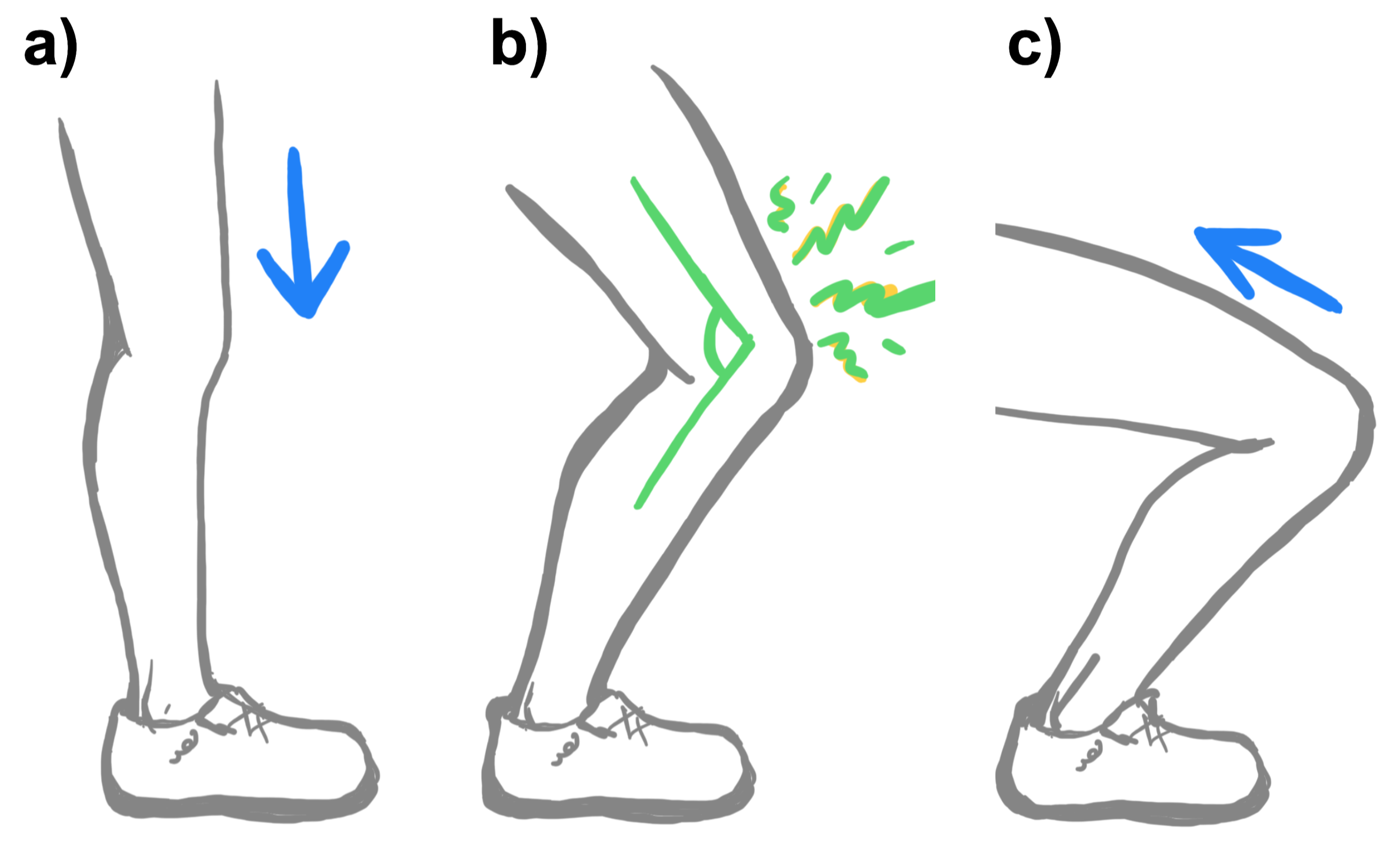
Figure 1: This shows how the modalities of haptic feedback that a user feels at various points in a squat exercise.
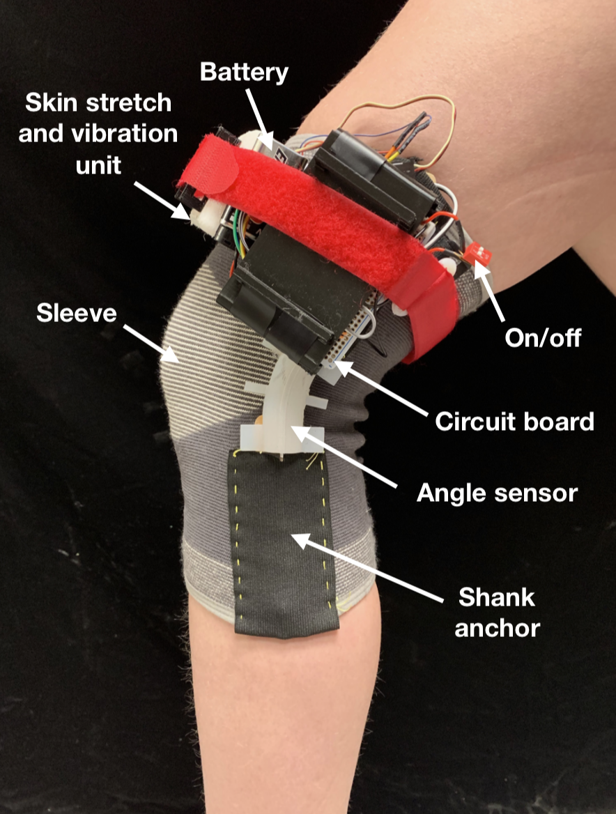
Figure 2: User wearing the final prototype and flexing knee
There are four key subsystems in the device, pictured in Figure 2. All subsystems are attached to the compression sleeve via sewn thread and/or small zip ties to allow for flexibility and conformability. These are (1) sensing (2) skin stretch (3) vibrotactile (4) power and microcontroller, and are described further in the following section (Figure 3).
Demonstration of Re-SWOLE
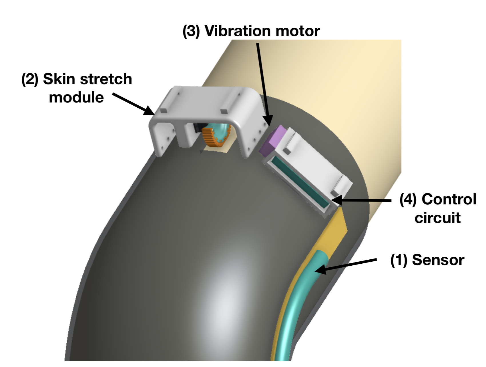
Figure 3: CAD model showing labeled subsystems on the device
(1) Sensing: measurement of the knee angle is achieved by a 2.5” long flexible resistor with a nominal resistance of approx. 25kOhm. As the sensor bends, the resistance changes and can be measured by the arduino using a 10kOhm resistor in a voltage divider. The sensor’s output value was mapped to an angle between 180deg and 90deg (Figure 4 A). The sensor was embedded in Dragonskin 10NV elastomer in order to give a larger attachment area and maintain the correct orientation with respect to the knee, without impeding its movement or the user’s (Figure 4 B, C).
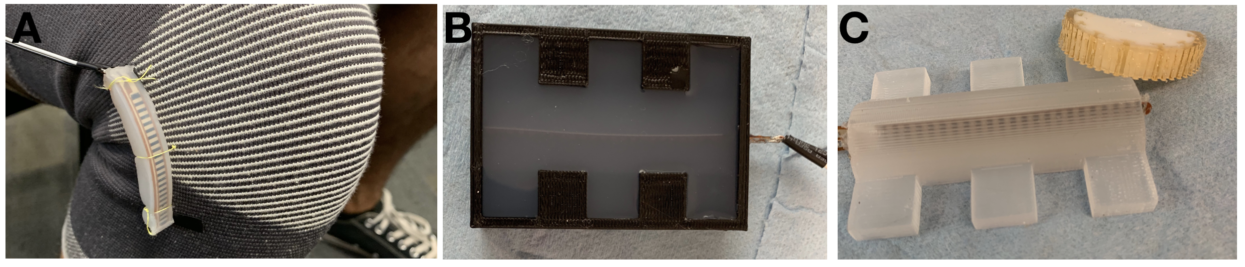
Figure 4: (A) Shows the flex sensor bending with the knee (B) shoes the mold embedding process for the FSR in elastomer (C) completed flex sensor
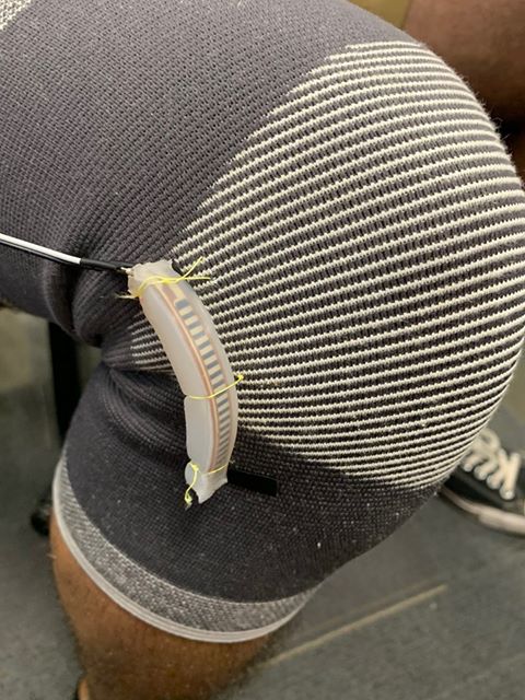
(2) Skin stretch Skin stretch is achieved using a 3D printed tactor attached to a Futaba S3114 servo. In order to get adequate friction with skin, shape deposition manufacture is used to embed a urethane surface into the tactor with a 3D printed mold shown in Fig 4. The tactor is placed against the skin in a neutral position when donned, and then rotates in either direction to stretch skin. The red strap shown in Figure 5 is used to tighten the assembly onto the user’s leg to ensure good contact with the tactor. A small window was cut in the compression sleeve to expose the skin to the tactor. The overall housing is printed out of Ultimaker 95A durometer TPU so that it it can bend and conform to different leg curvatures
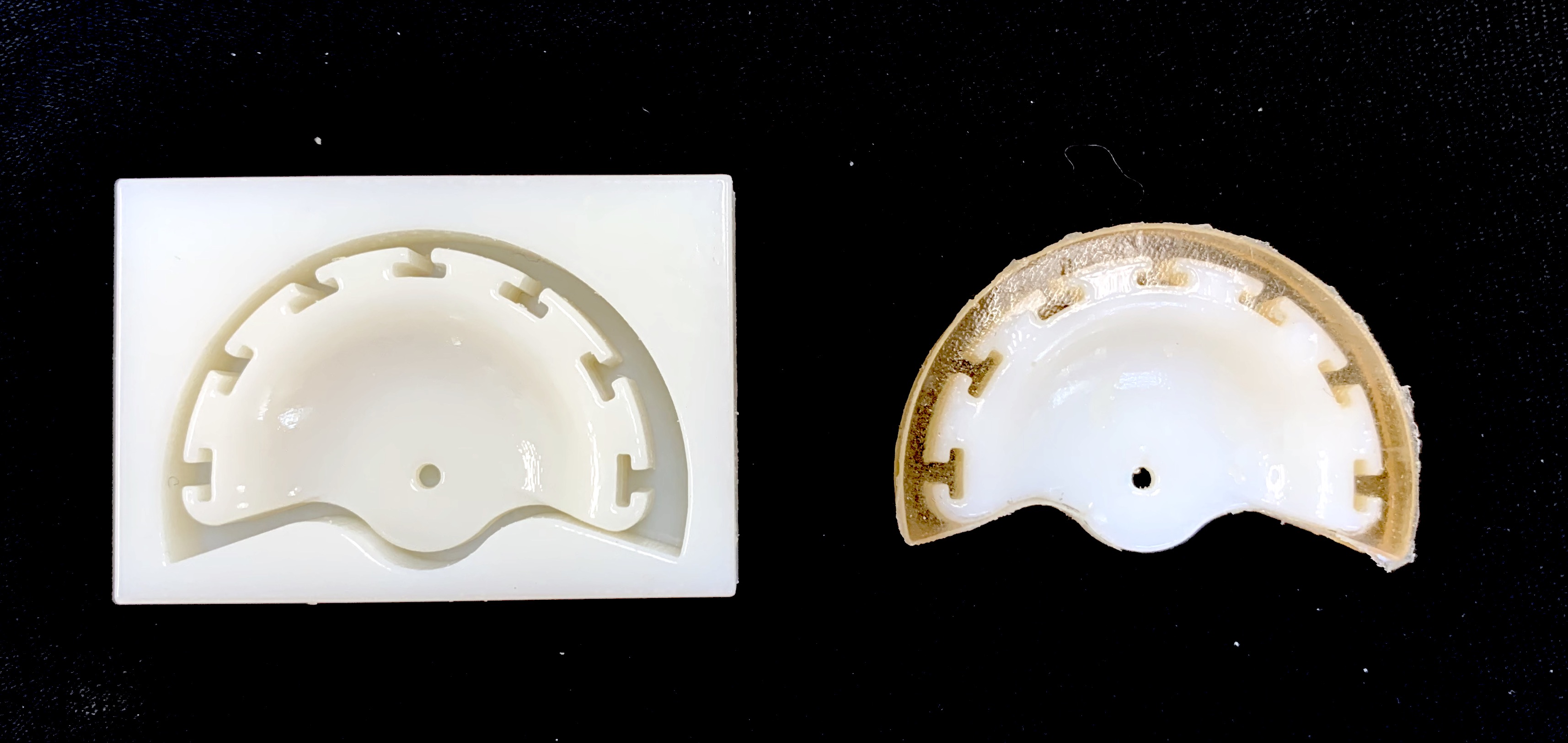
Figure 5: mold used as well as completed tactor
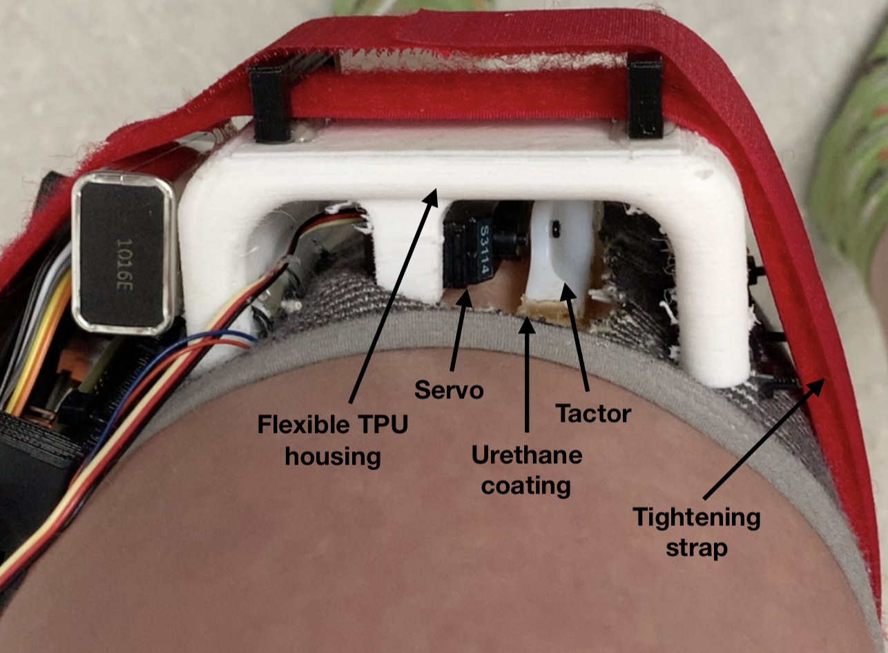
Figure 6: the fully assembled skin stretch module on a user
(3) Vibrotactile feedback A BestTong 3V vibration motor is run using a TB6612 motor driver from Adafruit. It is sewn on the inside of the fabric sleeve to reduce damping, beneath the skin stretch housing. The motor driver circuit is wired as described in its datasheet, and with three 3.3kOhm pull up/down resistors (Figure 7).

Figure 7: vibration motor used for vibrotactile feedback
(4) Power and microcontroller An Arduino Nano microcontroller was chosen for its size and ease of programming. It was soldered to a permaboard along with the vibration motor driver (Figure 7). Everything is powered off of a 9V battery. Connectors for all of the sensors and actuators are soldered in for ease of assembly.
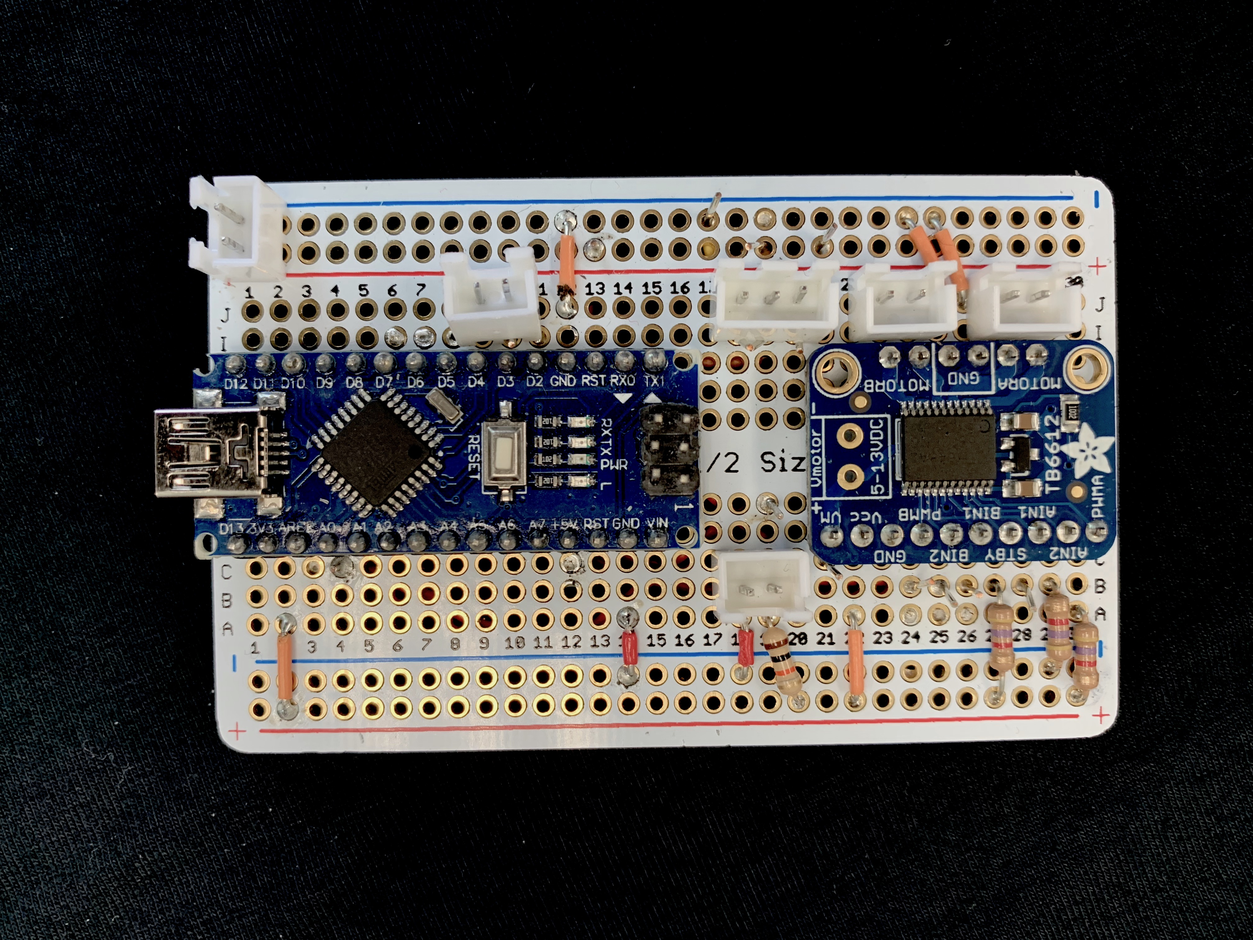
Figure 8: circuit including microcontroller, motor driver, and connectors for power, the servo, vibration motor, and sensor.
System analysis and control
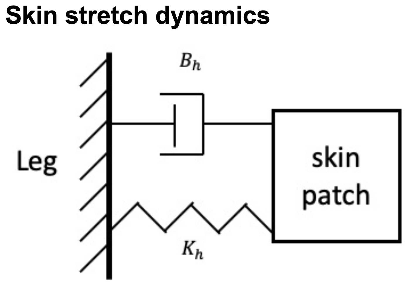
Figure 9
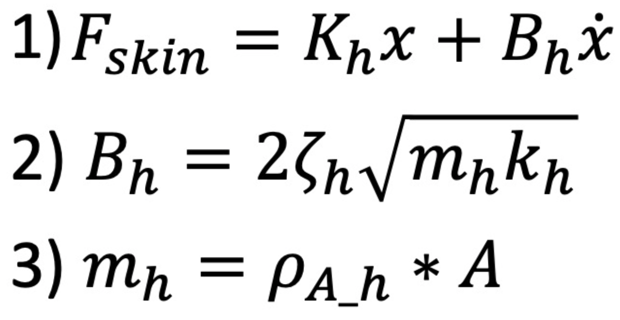
We model the patch of skin in contact with the tactor as a one degree of freedom mass spring damper system as shown by figure 9 and equation 1. Since the tactor is in contact with hairy skin on the leg, we use values for the spring constant (300N/m) and damping ratio (0.6) of hairy skin on the forearm found in literature [10], assuming that they share similar characteristics. Using equations 2 and 3, along with a characterization of the area density of skin [11], we are able to calculate the damping constant (0.66Ns/m) for the patch of skin in contact with the tactor.
Using this model, we chose a servo that would be able to exert the required force for skin stretch at the limits of its operation, with the goal being to stretch the skin at most 2 cm in either direction. We settled on the Futaba S3114 servo, which has a maximum no load speed of 670 degrees per second at 6V and a minimum stall torque of 14.7 N*cm at 4.8V. By combining the maximum rotation speed with our maximum desired skin stretch, we found that the force required to achieve this would be about 6.6N. Knowing that this is an exaggerated value because the tactor would never move at no load speeds when in contact with the skin, we compared this with the minimum force output of our tactor; 8.65N at 4.8V. This meant that our servo-tactor unit would be able to output over 1.3 times the required force on the skin in a worst case scenario.
Controls
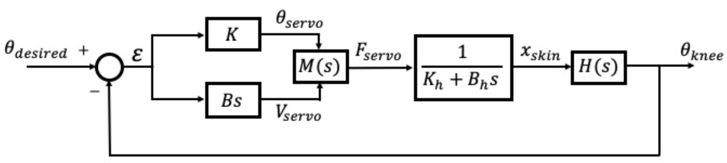
Figure 10:
We decided to control the force feedback in two ways. We send a tactor position command to the servo that is proportional to the error in knee angle. For this we use a gain of K equal to 5. Having a gain greater than 1 improves the resolution of feedback at lower values of error. We also modulate the voltage across the servo relative to the change in error with respect to time; a faster change in error would result in a higher voltage to increase the force and speed of the tactor as it moved to its target position. For this we use a gain of B equal to 10. Through pilot trial testing of the device, we found that this gain allowed for smoother rotation of the tactor and smaller rates of error.
Our system uses negative feedback with a unity gain, shown by block diagram of this system can be seen in figure 10. M(s) is the internal controller for the system coupled with the mapping of servo torque output to tactor force. H(s) is the controller internal to the human user, where they use the skin stretch feedback to adjust their knee angle. The block between M and H is the plant that represents the dynamics of the patch of skin in contact with the tactor. The gains for the control law implemented in software are shown prior to block M.
Experiment
The device was pilot tested on four users, with a target angle of 110 degrees, identified as a useful exercise in [4]. Each user performed three trials with either skin stretch and vibrotactile feedback, or skin stretch alone, for a total of 6 trials. The order was randomized for each user. The purpose of the device was explained, and the users donned the device on their left leg. Experimenters tethered the device by usb to a computer to control which experiment would be played and to record data. They assisted in placing the device on the user properly by checking the neutral angle read by the sensor. Before starting, the two forms of feedback were explained to the user, and they did a practice squat with each type of feedback. After completing the 6 trials the users doffed the device, and filled out a feedback form rating various metrics and providing optional additional comments.
Results
Performance with device
The results of these trials are shown in figure 11, where we map the knee angle over time for each subject with both forms of haptic feedback along with the target angle that we set for them. For a given subject, the trajectory towards the target angle is fairly similar, although the steepness of this trajectory appears to vary between subjects. This variation could be due to the personal choices in approaching the task, but more trials and analyses would have to be done to determine the true cause. It is unclear whether the similarities in trajectory are because of the skin stretch feedback. Running experiments without this feedback modality in addition to recording the angle commands to the servo throughout the squat would allow us to determine if this is the case. Overshoot magnitude and patterns varies greatly between subjects. Two subjects showed almost no difference in overshoot between vibration and no vibration cases, one subject showed consistent but small differences in magnitude, and one subject showed very noticable differences in magnitude. In all cases, as shown in table 1, the amount of overshoot with the vibration cue was less than that of the skin-stretch only. The width and flatness of overshoot varies between subjects.
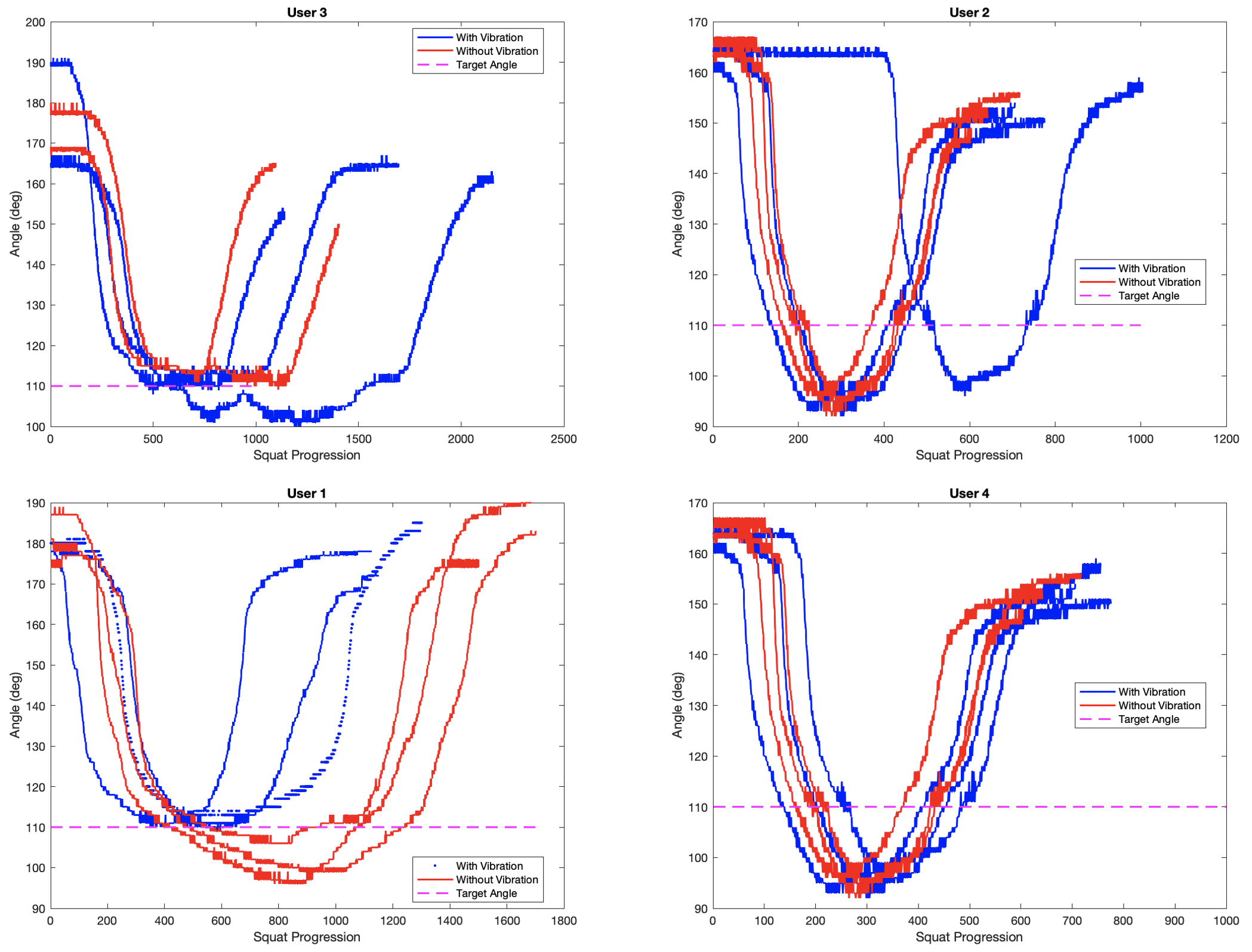
Figure 11
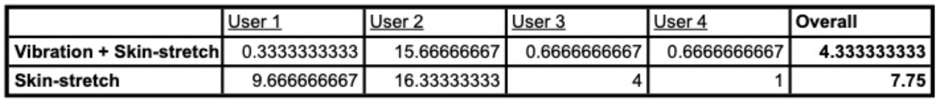
Table 1
User feedback
Five users rated the device on a scale from 1 to 5 in Comfort (“Uncomfortable” to “Comfortable”), Intuitiveness (“Device useless and does not guide you” to “Perfectly guides you to target”), and Ease of learning (“Hard to learn to use” to “easy to learn to use”). Out of a score of 5 users gave Comfort an average of 3.6, Intuitiveness 3.8, Ease of learning 4. Subjects reported a higher cognitive load resulting from interpreting the skin-stretch feedback. This could be addressed by changing the mapping of the skin-stretch feedback to provide changes in stretch direction at the beginning of each trial as well as when the subject reaches the target.
Future Work
Based on the results from our user testing, there are a few opportunities for future work.
Controlled study - we have compared target accuracy of skin stretch with vibrotactile feedback, and just skin stretch. However, in order to evaluate the efficacy of either mode of feedback, future work should involve a control case, in which measurements are taken on a user attempting to hit a target angle they are taught at the start, but without any form of haptic feedback. Furthermore, another study that could be performed is using vibrotactile feedback alone. The study could also test users at multiple angles to ensure they are not learning to hit a specific angle after a few trials. This new study would give clearer results on the efficacy of (1) no feedback (2) vibrotactile feedback (3) skin stretch.
New control schemes - some feedback we received in our user studies was that overshoot occured because it was difficult to differentiate small and no stretch around the target. A new mapping in our controller could rectify this by providing an upward stretch cue when the user has hit the target position, rather than no stretch. This way, they would be indicated to start rising already, rather than squatting further until the upward cue is large enough to feel.
Real form data - future studies could be run with physical therapists in order to more accurately measure proper form on professionals, and use the angles they choose for a full exercise routine, rather than just one squat. Furthermore, software could be setup so that physical therapists could conveniently receive the data from their patients wearing our brace, and draw conclusions or give recommendations based on what they observe.
Files
Arduino code, STL files, and Bill of Materials can be downloaded using the attachment link below:
References
- J. Nyland, E. Brand, and B. Fisher. Update on rehabilitation following ACL reconstruction. Open Access J Sports Med. 1:151–166, 2010.
- S. W. Arms, M. H. Pope, R. J. Johnson, R. A. Fischer, I. Arvidsson, and E. Eriksson. The biomechanics of anterior cruciate ligament rehabilitation and reconstruction. Am J Sports Med. 12(1):8-18, 1984.
- B. W. Brewer, J.L Van Raalte, A. E. Cornelius, and A. J. Petitpas. Psychological factors, rehabilitation adherence, and rehabilitation outcome after anterior cruciate ligament reconstruction. Rehabilitation Psychology 45(1):20-37. 2000.
- D.E. Toutoungi, T.W. Lu, A. Leardini, F. Catani, J.J. O Connor. Cruciate ligament forces in the human knee during rehabilitation exercises. Clinical Biomechanics. 15:176-187, 2000.
- M. Husman, H. F. Maqbool, M. I. Awad, A. Abouhossein, and A.A. Dehghani-Sanjj. A wearable skin stretch haptic feedback device: Towards improving balance control in lower limb amputees. EMBC. 2120-23, 2016
- J. W. Bark, P. S. Wheeler, and M. R. Cutkosky. Comparison of skin stretch and vibrotactile stimulation for feedback of proprioceptive information, 71–78, 2008.
- M. A. B. Husman, H. F. Maqbool, M. I. Awad, A. Abouhossein, and A. A. Dehghani-Sanij. A wearable skin stretch haptic feedback device: Towards improving balance control in lower limb amputees. 2120–2123, 2016.
- O. Kayhan, A. K. Nennioglu, and E. Samur. A skin stretch tactor for sensory substitution of wrist proprioception. 26–31, 2018
- H. J. Witteveen, E. A. Droog, J. S. Rietman, and P. H. Veltink. Vibro- and electrotactile user feedback on hand opening for myoelectric forearm prostheses. IEEE transactions on biomedical engineering. 59(8):2219–2226, 2012.
- E. Sandford, Y. Chen, I. Hunter, G. Hillebrand, and L. Jones. Capturing skin properties from dynamic mechanical analyses. Skin Research and Technology 19:339-348, 2013.
- X. Liang and S. A. Boppart. Biomechanical properties of In Vivo human skin from dynamic optical coherence elastography. IEEE Trans Biomed Eng. 57(4):953-959, 2010.
Appendix: Project Checkpoints
Checkpoint 1
- Goal 1: all hardware components and circuitry selected and ordered
Mostly Complete: We currently have an MPU-9250 for tracking the motion of the knee. We are currently working on processing the data from the IMU for interfacing with our skin-stretch mechanism. We have decided to use Dycem for our first iteration of the skin stretch device. We have not yet decided on a motor for the skin stretch, but we plan to use the Hapkit motor for testing until we characterize the skin stretch dynamics. We have a flex sensor, wifi enabled microcontroller, and vibration motors in the event that we have time to add vibration cues for squat depth feedback.
- Goal 2: CAD of all custom components to mount hardware into brace
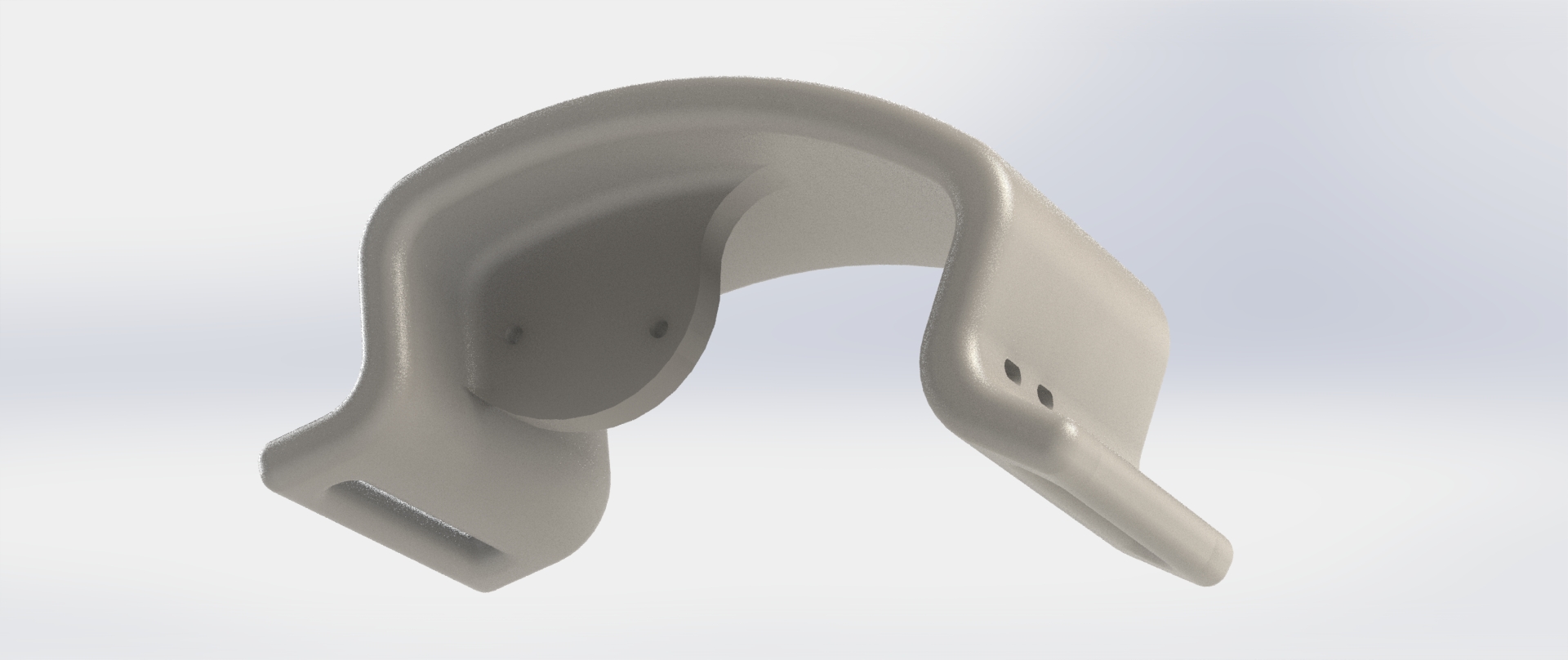
Complete: We have completed the CAD for the rigid arch that will house our skin-stretch system. This custom part provides a mount for the motor and for the spring, as well as a slot to slide the velcro straps through for secure attachment around the shank. We plan to print our custom part using a Form 2 and “flexible” resin to create a more comfortable fit for the wearer. Here is a rendered view of the CAD model:
- Goal 3: brace purchased and modified for easy wear and to accommodate electronics
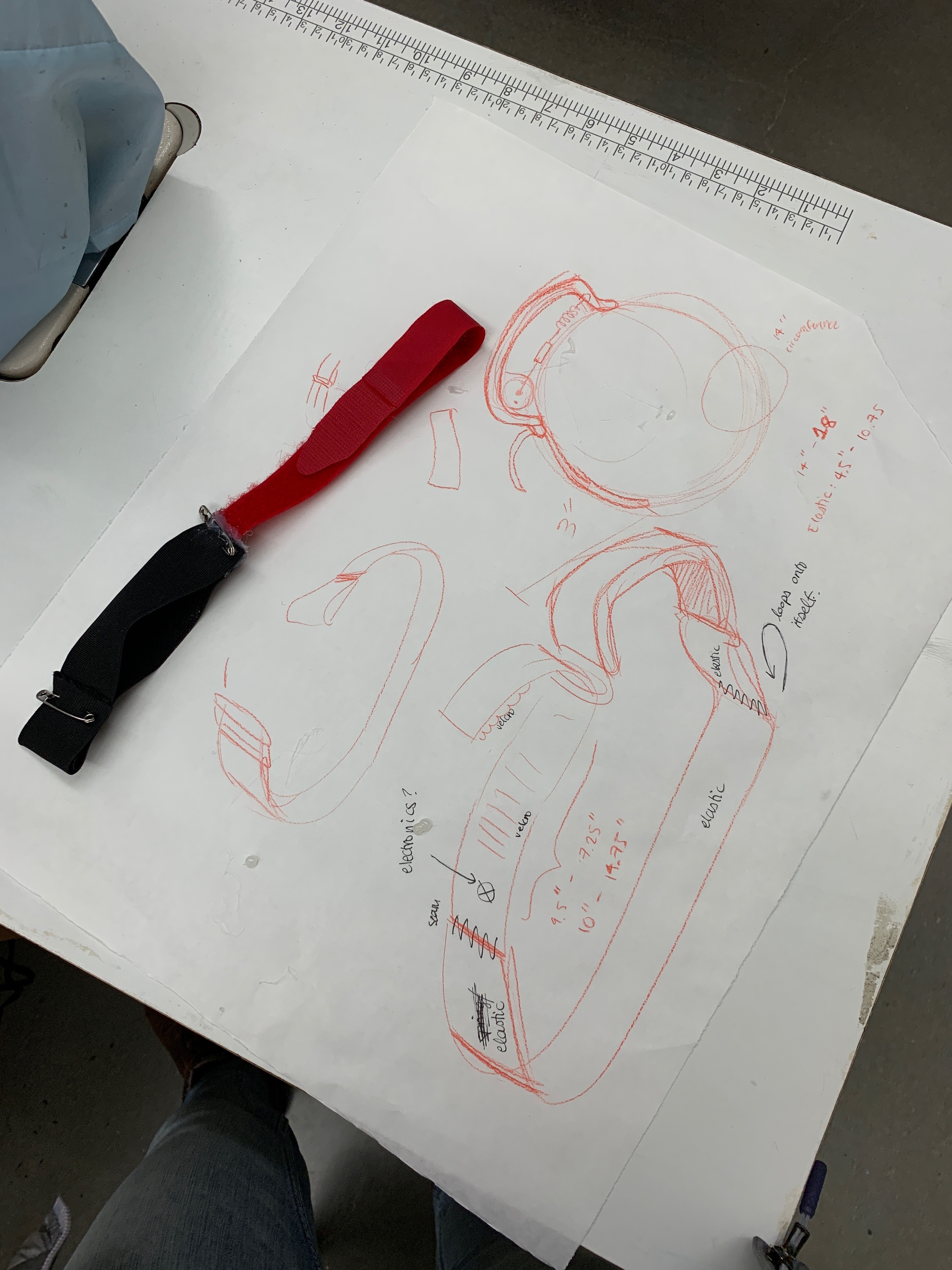
Complete: Because most purchasable braces provide rigidity and structural support to the knee, we decided to create our own brace from scratch. Currently, we have connected a velcro strap to a thicker elastic strap which will loop through the slots of the custom printed part of the skin-stretch module.

- Goal 4: begin gathering data on proper squat form using sensors adhered to our limbs while performing squats under supervision by a professional
In Progress: we are in the process of taking IMU measurements on ourselves, however due to a delay in the shipping of the IMU, our sensing code is not robust enough to use up therapist time at Vaden yet. However, we are able to take data on ourselves, and need to continue to filter the accelerometer output before we take the next step.
Checkpoint 2
- Overview:
Generally, we decided to focus our project on providing haptic feedback and guidance for proper squat depth instead of correcting for valgus or varus knee. We decided this because we had been having trouble with filtering the acceleration data on our IMU to be good enough for position sensing of the knee. Instead, we know that we can more easily and accurately use a flex sensor to sense the knee flexion/extension angle (in the sagittal plane). We will still use skin stretch, however we settled on a more robust design involving the use a servo arm in the shape of a sector whose circular surface interfaces with the skin to stretch it. With this skin-stretch set-up, we will implement position control of the tactor with the servo, with a controls algorithm that takes into account the dynamics of skin stretch of the anterior skin above the knee throughout a squat, for which the angle of knee bend will be reported by the flex sensor.
- Goal 1: skin-stretch portion of device fabricated
- New skin-stretch mechanism; pivoted from spring in series with tactor actuated by servo toward a simpler design consisting of a tactor on a sector directly mounted to the servo shaft.
- Circuit completed to run vibration motor, servo, and read flex sensor. Everything runs off battery. Next step: solder into a permaboard and interface with WiFi arduino
- Flex sensor reads to ~1deg angle and is used to adjust the servo position

- Tactor completed: a 3D printed sector mounted on the servo with a soft rubber (Ecoflex 00-30) molded directly into it for traction against skin
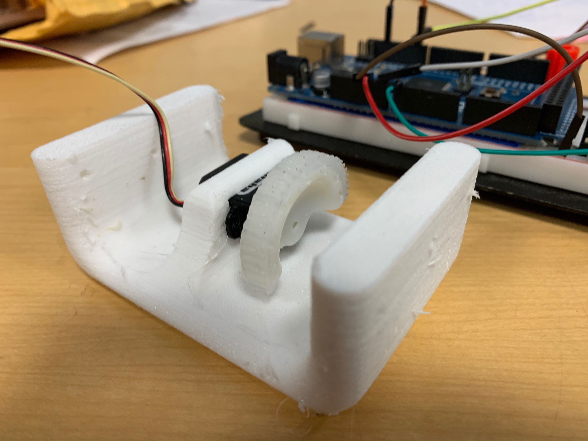
- Housing v2 pictured: the part is 3D printed from a TPU material so it is somewhat flexible and conformable to the curvature of the thigh. Next iteration will include mounting holes for the soldered circuit, vibration motor, and battery.
- Brace: we have a stretchable knee brace to sew the housing onto. A flex sensor has been encased in silicone to make it conform well to the leg once sewn onto the brace:
- Goal2: create controls algorithm and integrate it with MCU to the motor and sensors on the wearable
- Controls algorithm:
- We are currently using a direct mapping of flew sensor angle to servo angle to achieve bidirectional feedback with a total distance of about 2cm.
- Implementation:
- We implemented a running average to smooth out the data from the flex sensor.
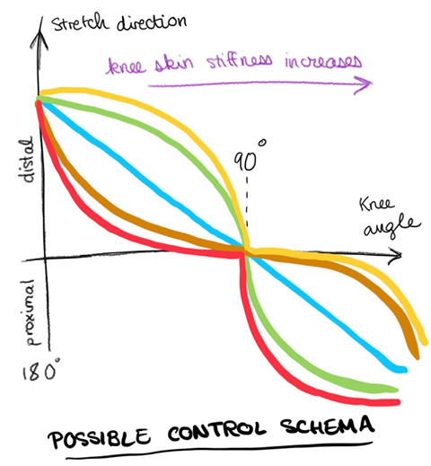
- We have several controls schemes, show below, that we plan to compare in the coming days. Theoretically, we see that the stiffness of the skin increases when the person is squatted lower because of the muscle pressing against it more. So we suspect that we will need to provide more deformation to achieve the same sensation at those points. We are experimenting on ourselves to see if we can feel the difference and provide a smooth transition in magnitude of stretch felt.
- Controls algorithm:
- Goal 3: tune control algorithm to work well on the whole team’s legs. Test various magnitudes and directions of skin stretch to get the best effect.
- We are currently testing simple models for position control of the tactor using the servo (described further in previous goal). This goal requires further work to get the best feeling effect.