

David And Phong
Haptic Rendering to Teach Principles of Optics
Project team members: David Saltzman and Phong Pham

A model of the 2-DoF haptic device
Optics, the science of light, is often taught in high school physics classes. It is also often unintuitive and misunderstood; students have little experience with how light operates on a low level. The aim of this project is to stimulate interest in and bolster understanding of optics by designing and implementing a haptic device that can illustrate principles of optics in an intuitive way. This is accomplished by building a 2-DoF mechanical system; the user moves the end effector, which represents a photon, about a virtual environment. When he or she encounters a boundary between materials, a force in the direction of reflection or refraction is applied. The user can explore different materials and the differences in how light behaves. The system in practice functions as intended.
On this page... (hide)
Introduction
The goal of this project is to build a haptic device and virtual environment for that device that can be used for optics education, specifically by rendering reflection and refraction. In high school environments, not many students have an opportunity to practice the optics principles in the laboratory, and many do not learn about them at all. Therefore this device addresses the need for a more hands-on experimental tool to illustrate the effect of optics. Current research has demonstrated that virtual environments are proven to be effective ways of learning physics; adding haptic feedback could increase effectiveness further still in two ways. The first is that haptic feedback is more visceral; with standard physics education, students know what it feels like to apply a force to a ball at a certain angle. This is not the case with optics; using a haptic feedback gives students a feel for optics that they wouldn't otherwise have. They are able to move the photon at will and feel what happens when they cross the boundary at different angles. The second reason for haptic feedback is that if the student moves some object around to represent the photon, if the photon would bounce, a force must be applied to the object to cause it to move in the same direction as the photon would move. Aside from feeling the force, the user feels that they have moved in the direction the light would bounce. Allowing exploration and feeling how light bounces makes it more intuitive how light behaves, increasing the student's understanding of optics.
Background
There has been no published prior work in using haptic systems for rendering optics effects, so the overall plan was original. However, many 2-DoF planar systems have already been designed. Many CS235: Applied Robot Design projects were similar to what we needed and were built using materials and techniques available to us. Videos of their final projects [1] were explored, and elements of some of their designs were incorporated into our design.
Basic reflection and refraction are well understood and use simple formulas. The angle of refraction is calculated according to Snell's law [2]:
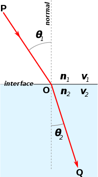
Figure 1. Angle of refraction
However, light sometimes internally reflects. This is the case when the angle of incidence is greater than the critical angle:

Figure 2. Total internal reflection

These equations determine in which direction the light bounces when it hits the boundary.
Methods
Hardware design and implementation
Since the 2-DoF system is desired, the four bar linkage mechanism has been selected as a principle design of the mechanical hardware. Because the system is intended to simulate a photon in a vertical plane, the four-bar linkage is rotated vertically so that the user experiences the actual feeling of the photon in a plane that is in the same orientation as the laptop screen.
The capstan drive is the main drive system that connects the motion between the motor and the link. The capstan drive has been selected due to its lack of friction and light weight. In addition, the capstan drive is more flexible in how it is attached when assembling the system.
The mechanical system is designed and modeled in SolidWorks. Specifically, the main assembly contains 7 sub-systems:
(1) The base
(2) The motor holder, motor, and motor pulley
(3) The short-link drum
(4) The long-link drum
(5) The short link
(6) The long link
(7) The motor pulley
All of them are made of quarter-inch-thick duron (except the motor holder small piece made of acrylic), and were lasercut in the Room 36 (Product Realization Lab.)
All the dimensions in the CAD drawings are in inch units.

Figure 3: The mechanical parts were lasercut in the PRL
(1) The base is a 1-inch thick square of 4 concatenated pieces. It is to hold the weight of the whole system, as well as the electronics.

| 
|
| Figure 4: (a) The base design | (b) CAD dimension |
(2) The motor holder assembly: There are 2 designed pieces to hold the motor. 3 big pieces are attached together to hold the majority of the motor weight and for the main shaft holder. The small piece, made of acrylic, for its transparency, is to fix the motor position to the holder.

| 
|
| Figure 5: (a) The motor holder assembly (front view) | (b) The motor holder assembly (left view) |

| 
|
| (c) The big motor holder 1 CAD dimension | (d) The small motor holder CAD dimension |
(3) The short-link drum

| 
|
| Figure 6: (a) The short-link drum | (b) The short-link drum CAD dimension |
(4) The long-link drum

| 
|
| Figure 7: (a) The long-link drum | (b) The long-link drum CAD dimension |
(5) The short link:

| 
|
| Figure 8: (a) The short link | (b) The short link CAD dimension |
(6) The long link: The short-link drum is connected with the long link, and then the short link. The long-link drum is connected with the long link to complete the four bar linkage system.

|
| Figure 9: (a) The long link |

|
| Figure 9: (b) The long link CAD dimension |
(7) The motor pulley: The motor pulley is modified from the model that has been used in the class. Modifications include the thread- pitch and the overall length. The motor pulley is attached to the motor via a set-screw in order to transmit the torque from the motor to the capstan cable. The capstan cable is attached to the system by the screws and nuts along the perimeters of the drums. The range of motion of the capstan drive is calculated to be 0.65in wide, which is well under the width of the drum.

| 
|
| Figure 10: (a) The motor pulley | (b) Motor pulley in the physical system |
The final assembly is as below:
|
| 
|
| Figure 11: (a) Final assembly in Solidworks | (b) Final physical assembly |
Video 1: The model of the mechanical system in SolidWorks
Electronics layout
The electronic components were two Arduino Uno microprocessors, a combination pushbutton-switch / knob-potentiometer, two Maxon RE25-118743 motors with encoders, and several resistors and capacitors.
One Arduino acted as the master, and had the following pin configuration:

Figure 12: Pin layout for master Arduino
The other Arduino acted as the slave, and had the following pin configuration:

Figure 13: Pin layout for slave Arduino
To communicate with each other, each Arduino sent a PWM signal to a low-pass filter, then the analog output of the low-pass filter was sent to an analog input of the other Arduino. Each of the two low-pass filters was a simple RC circuit configured as shown below:

Figure 14: Circuit layout for low-pass filter
The pushbutton / knob was connected to the master Arduino. A pull-up resistor was added to the switch, and an additional resistor was added to the potentiometer to create a voltage divider, as shown below:

Figure 15: Circuit layout for pushbutton / potentiometer
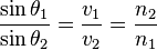
!!! Software architecture
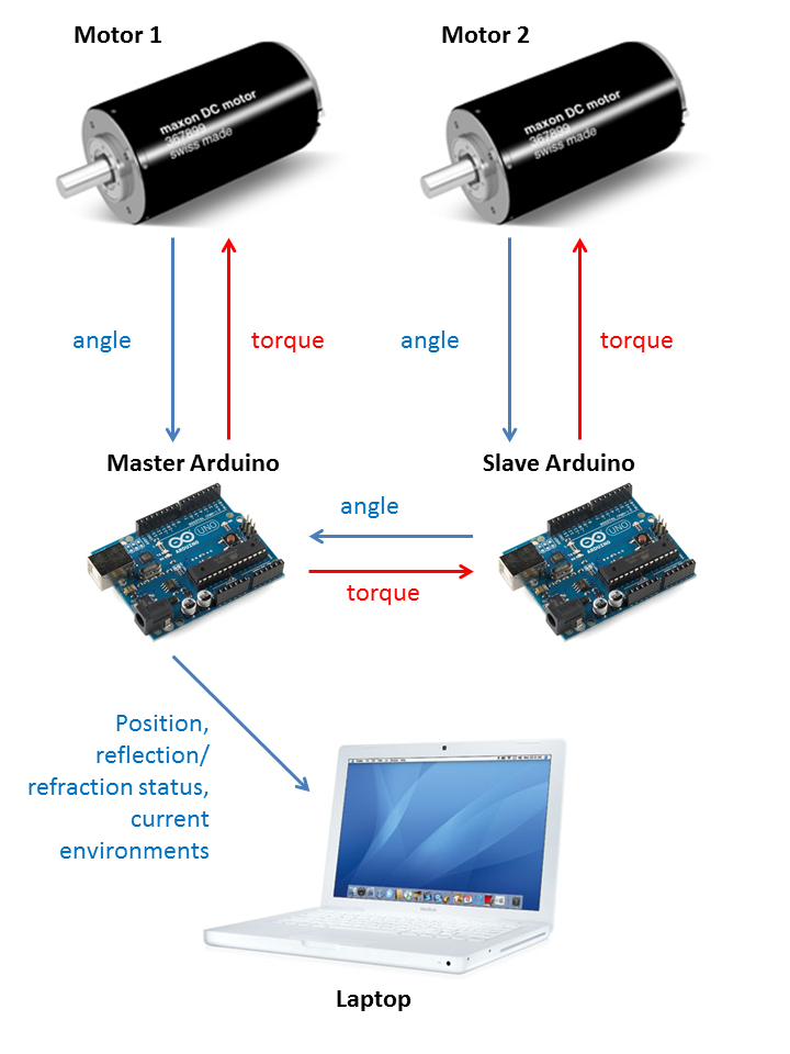
Figure 16: Software architecture
Each of the two Arduino microprocessors read the angle of one motor from an encoder and output a torque to that motor via PWM. One Arduino, the master, read the encoder value from its motor, ran the simulated virtual environment, and sent information to the laptop to be displayed. The other Arduino, the slave, read the encoder value from its motor and relayed that value to the master.
The master Arduino ran a control loop at 357 Hz, the fastest speed the Arduino could consistently run all of the required computations. It calculated the position from the encoder angles, computed the velocity using a low-pass filter, checked for boundary crossings, calculated the desired force, calculated the required torques to produce that force, then wrote a PWM signal corresponding to one of the desired torques to its motor and another PWM signal to the slave to be relayed to that motor. Serial communication to the laptop was asynchronous and occurred every 20 control loops.
The laptop was used only for visual effects. The graphics and communication with the master Arduino are done in Processing. The values that were sent to the laptop were the (x,y) position of the photon, the incident angle, the refracted angle, which way the light was bouncing if any, and the indices of refraction of the two materials.
System analysis and control
The range of motion of the four bar linkage was defined based on the simulation on SolidWorks. By simulation, the range of motion for our device was approximately 21in by 6in, which gave us enough workspace for our application.

Figure 17: The range of motion in simulation
In the physical system, the range of motion was defined by a washer and a stopper, that would stop the drum from going beyond the given range.

Figure 18: Washer and stopper
To analyze the system to control it, various parameters were labeled as shown below:

Figure 19: Four-bar linkage model
The encoder on each motor measured the angles θ1 and θ2. From these, the position of the end effector was calculated:
x = l sin(θ1) + p sin(θ2)
y = l cos(θ1) - p cos(θ2)
Then to display any given desired force, a mapping from end effector force to the torque of each motor was calculated.
The desired forces were first converted from (x,y) components in the frame of the room (Fx, Fy) to (x,y) components relative to the long link (labeled p-d) on top of the device; Fx_bar was along the bar and Fy_bar was normal to the bar.
F_angle = atan2(Fx, Fy)
F_mag = sqrt(Fx^2 + Fy^2)
θ = 𝛑/2 - θ2
Fx_bar = F_mag * sin(F_angle - θ)
Fy_bar = F_mag * cos(F_angle - θ)
To calculate the two motor torques from Fx_bar and Fy_bar, first the components of the forces generated by each motor were calculated. The component from motor 2 (the motor turning the drum with angle θ2) was:
Fx_bar_m2 = 0
Fy_bar_m2 = 𝜏2 R / (r p)
And the component from motor 1 (the motor turning the drum with angle θ1) was:
Fx_bar_m1 = 𝜏1 R / (r l) cos(θ1 +θ2 - 90�)
Fy_bar_m1 = -𝜏1 R / (r l) sin(θ1 + θ2 - 90�)
Summing these and solving for the torques yielded:
𝜏1 = Fx_bar r l / (R cos(θ1 + θ2 - 90�))
𝜏2 = (r p / R) * (Fy_bar + 𝜏1 (R / (r l)) sin((θ1 + θ2 - 90�))
In addition, gravity compensation was added to prevent the system from falling while unattended, as well as to allow the user to move the end effector without carrying its weight.
𝜏1_grav = k1 sin(θ1)
𝜏2_grav = k2 sin(θ2)
An initial estimate for the parameters k1 and k2 was calculated based on linkage lengths, then the numbers were adjusted in practice until the system held upright independently. The natural friction of the system provided the difference between the calculated required gravity compensation and the exact weight of the system.
The torques from the desired forces were added to the torques for gravity compensation to determine the motor output. If the total torque on either motor required a duty cycle greater than 60%, both torques were scaled down equally until the higher torque was a 60% duty cycle. Higher than 60% duty cycle caused the motor shaft to vibrate within the shaft; both torques were scaled down equally to preserve the direction of the force.
Rendering Reflection and Refraction
When the photon crossed a boundary, an end effector force was calculated to apply to the user. The direction of the force was the direction in which light would bounce; if the incident angle was greater than the critical angle, the photon internally reflected at an angle equal to the incident angle. Otherwise, the light refracted at an angle calculated by Snell's law:
θ_crit = asin(n2 / n1)
θ_reflection = θ_incident
θ_refraction = asin(n1/n2 * sin(θ_incident))
The magnitude of this force was proportional to the velocity of the photon when the boundary was crossed. This impact force then decayed exponentially, with a half-life of 96ms, ending after 500ms. There was not allowed to be another bounce within 500ms of the first bounce; for regular use, this prevented random noise from accidentally causing unintended boundary crossings. In addition, a spring force was applied to push the user back into the material the photon was supposed to be in to ensure that the user did not slip through.
Educational demonstration
The educational objectives of this system were to make the way light behaves when it crossed a boundary between materials more intuitive. To allow exploration, the student was able to freely move the photon around and cross the boundary at any angle. In addition, there was a knob with a built-in pushbutton that allowed the user to change the materials; pushing the button switched between several pre-defined environments and custom mode. To give a range of indices, the predefined environments were air-water, oil-water, and air-diamond. These were chosen as materials that students would have some intuition with already. Air-water had a ratio of indices of refraction of 1.33, oil-water 1.11, and diamond-water 2.42. In custom mode, the user could turn the knob to change the index of refraction of the bottom material between 1.0 and 4.5.
To make a reflection or refraction intuitive and clear, there was a haptic component and a visual component each time light crossed the boundary. The haptic component was a decaying force in the direction the photon would move; this was necessary for creating the actual bounce. If there were only a visual component, the student would not automatically move in the desired direction; the visuals could show the direction the light would move, but it was only be intuitive because the light did actually move in that direction. However, the visual component was necessary to show what was going on. Without the graphics, it was not clear why the user was bouncing as they were. The visual component showed the photon and the materials so the student knew when the photon crossed the boundary. In addition, whenever there was a reflection or a refraction, lines were shown to indicate the path of the photon (a trace of where the photon had been was also shown), and the incident and reflected/refracted angles were displayed. The indices of refraction of the two materials were also shown.
A screenshot of refraction between water and air is shown below:

Figure 20: Water and air environments
And a screenshot of total internal reflection reflection within diamond is shown below:

Figure 21: Diamond environment
The first component of a student's experience was exploration. The student would move the photon at different angles and speeds towards the air-water boundary and see how the photon reacted. Then different materials were shown to illustrate how the material affects the reflection or refraction.
The second component was trying to answer several questions. Three questions were formulated that the student could figure out from the simulation. The questions were:
1. When you see a fish, is it actually closer or further than you think?
2. Why are diamonds so sparkly?
3. How would you build an invisibility cloak?
These questions were designed to be engaging, as they focus on things people might actually experience or think about already, and to ensure that students learn whether light bends towards or away from the normal when changing to a material with higher optical density, learn that there is a lot of internal reflection in diamonds because of their high optical density, and think about how to use the index of refraction for design.
Results
The mechanical system felt smooth and had a working area large enough for the application. Control functioned as expected, and gravity compensation generally held the system upright without user input. One notable mechanical weakness was the motor pulleys; these were pulled off after repeated use. After a design change to add stoppers that limited motion to a safe range, the motor pulleys no longer broke, but still sometimes fell off. The motor forces were also limited because too large a torque caused the motor shafts to vibrate within the motor pulleys, but a 60% duty cycle was found to be safe and was sufficient to render a reflection or refraction.
The combination of the haptic force in the direction of the bounce and the visual rendering generally created a compelling bounce sensation. It was difficult to feel exactly at what angle the force was pushing, but with visual feedback it became more clear, and the force was useful for ensuring that the photon went in the right direction. It was very clear how light refracted more sharply and internally reflected more often with the diamond-air boundary than with the water-air boundary.
The following video shows how the system works.
Video 2: The final system and its rendering
Students at the demo did get some sense of how light reflected or refracted. They understood the concept that the end effector represented the photon (a yellow circle of duck tape on the end helped a surprising amount; before the demo, when others tried the system, they often held the system in the middle, which did not map to the photon. With the yellow circle all students held the correct part and understood the mapping). They learned that light internally reflected in diamond and optically dense materials more often in water, and some were able to answer the "why are diamonds so sparkly?" question. Most users did not get to the "how would you build an invisibility cloak?;" only one particularly curious user did, and she did come up with the idea that various materials would be needed to refract light around an object (in practice, metamaterials are used so that there can be gradient indices of refraction, so that answer is correct).
The "when you see a fish, is it actually closer or further than you think?" question caused more debate. Every single person who answered before playing with the simulation with that question in mind answered further away. Some tried to figure it out by simulation before answering; those were mostly able to correctly answer that the fish is closer than it appears because the light bends down towards the fish. Those users learned in which direction light refracts; others were told the answer and understood the explanation, but are less likely to remember it than those who figured out the answer themselves. All students were engaged by the concrete nature of the question, though many were unsure how to figure out the answer from the simulation (several asked where the fish was).
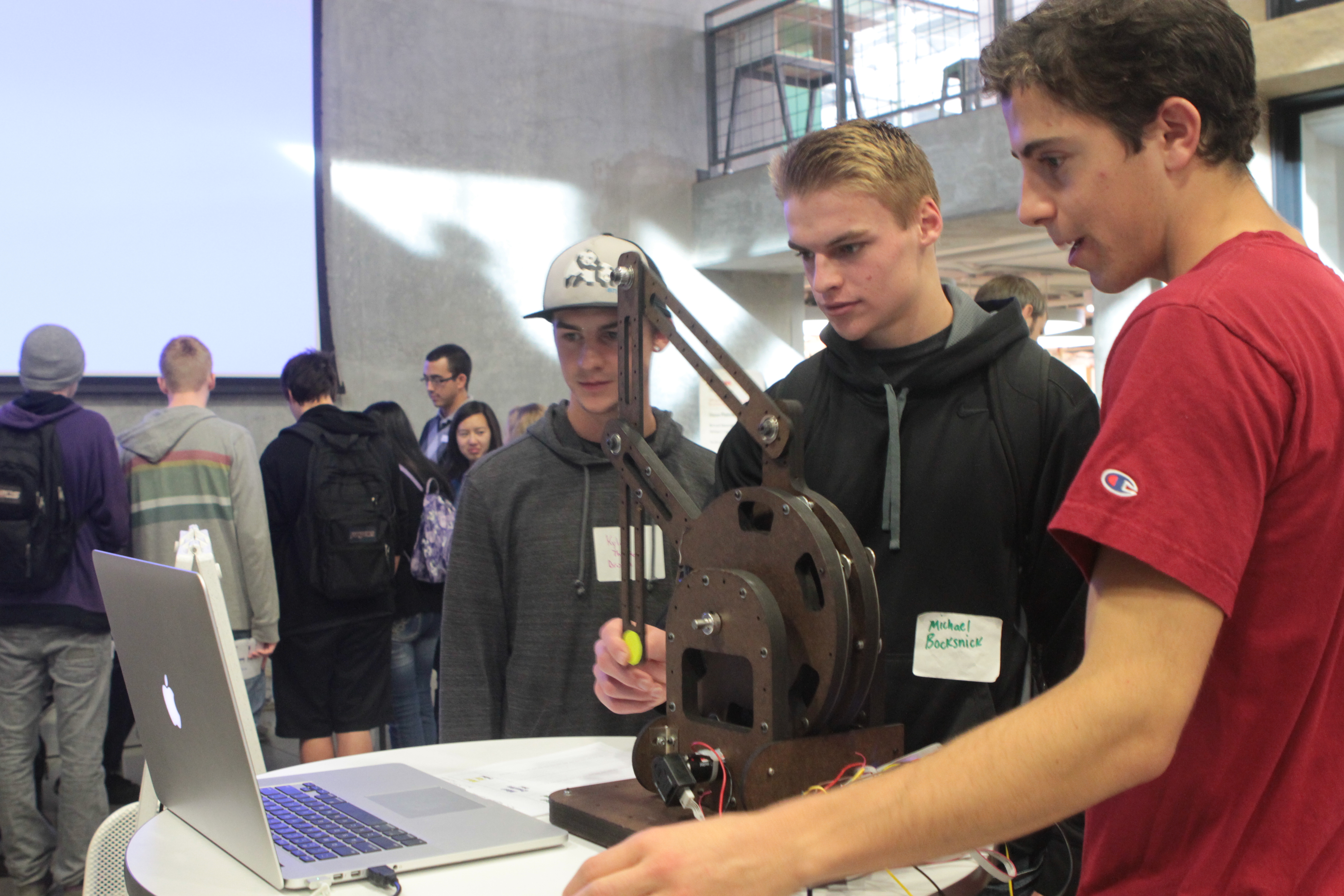
Overall, the students were excited to see and experience the haptic feedback and learn a bit about optics. More photos of the students participating in the demonstrations are as followings:
| 
| 
| 
|

| 
| 
| 
|

| 
| 
| 
|
| 
| 
| 
|

| 
| 
| 
|
Future Work
A new, more robust motor pulley design would strengthen the system. Possibilities include using a press fit that takes advantage of the flattened shafts instead of a set screw, stronger materials, or eliminating the ridges. Without the threads, the capstan cable can align itself to a comfortable arrangement to hold the tension between the motor pulley and the drum; thus reducing amount of work to align the threads.
One improvement on the application end could be to assign users to go fishing with a laser. This would require them to think about what angle to go in to the water while accounting for how the light bends. This would engage users as well as force them to understand in which way light refracts to be able to complete the task. It would also be more memorable than abstract angles of refraction. Additional levels using more concrete examples could be used to help users understand other optics principles better.
This system has not yet been tested with students already learning about optics. It is designed to teach something to people who know nothing about optics beforehand, but it is also designed to make optics more intuitive to those who are formally studying it. In most optics lessons, the math is central but the intuition about how light behaves is neglected. If students who already know something about refraction and reflection try the system, they could feel and see refraction and reflection in context and work that in to their mental model of how light behaves. Testing to see how effective this would be remains future work.
Acknowledgments
We would like to thank Allison Okamura for guidance towards the system as it is, Xiyang Yeh for advice about the mechanical design, Nick Colonnese for the motor pulley design and file, and Max Alexander for consultation on how to effectively teach with our system.
Files
Below is the link to download all the code that include the Arduino software control and the Processing rendering Attach:ME327_Optics_Code.zip
The price break-down for the entire system is attached: Attach:Optics_Project_Part_List.pdf
References
[1] System design inspired by http://www.youtube.com/user/StanfordCS235
[2] Optics information from http://en.wikipedia.org/wiki/Snell%27s_law
[3] Images for the user interface from http://images.google.com
Appendix: Project Checkpoints

Checkpoint 1
Goal 1: Complete mechanical design
This goal has been completed. Several broad 2-DoF system designs were explored, and one was selected and modeled in SolidWorks. The end effector force was calculated as a function of the motor torques and the configuration of the system to guide the design.
The assembly design of the 2-DoF device:

The front view:

The left view:

The top view:

Range of motion: By simulation, the range of motion for our device is approximately 21in by 6in, which gives us enough workspace for our application.
Goal 2: Complete mechanical assembly
This goal has been started but not completed, as the parts required for the system only just arrived. The wood has been laser cut to the first iteration of the design. However, on beginning assembly, it became clear that the wood thickness was slightly less than anticipated, and not all of the parts fit properly; another iteration of the SolidWorks models that will account for this difference is underway and new parts have been ordered.
Some photos that highlight the activity at the machine shop:

Checkpoint 2
Goal 1: Complete mechanical assembly
Mechanical assembly has been completed. The inertia of the system is fairly significant, but it generally moves smoothly.
After some (exhausting) iterations, the mechanical assembly has finally been done. Some notes: the shaft and its corresponding items (ball bearings, shaft collars, etc) were downsized due to optimization of weights and size of the mechanical design.

Capstan drive and motor pulley: this assembly step is tricky and requires some practice before getting it done correctly. Now the system is running robustly and smoothly. It is ready to be controlled!

Goal 2: Complete mechatronic interface
The mechatronic interface has been completed. There are two Arduinos with Ardumoto shields; each connects to a motor and the associated encoder. One is a slave and only reads the encoder value and sends motor commands; it sends the encoder value and receives motor commands from the master Arduino. The master performs the kinematics calculations and models the virtual environment.
Goal 3: Preliminary control software
Control software is still being debugged. The position is correctly calculated and the motor torques seem to be correctly calculated, but fully correct control is still in progress.
Checkpoint 3
Goal 1: Complete Control
Control has been completed and all of the bugs have been worked out. Gravity compensation has also added so that the system does not fall and the user does not have to carry the weight.
Goal 2: Complete Software rendering
Software rendering has been completed. The photon on the screen tracks the position, and the incident and reflected / refracted angles are shown. A button and knob has also been set up so the user can change materials or adjust a custom material.
Goal 3: The system is ready to roll!
Yes!