

Gerard Ransom Thomson
Air-Hockey with AI Guidance
Project team member(s): Roshail Gerard, Elliot Ransom, and Cole Thomson

Air hockey is a convenient testbed for designing 2-DoF haptic environments due to its familiarity, clear objective, and relative simplicity. In this exercise, we design, build, and program a 2-DOF virtual air hockey experience. We utilize a 5-bar linkage pantograph mechanism that applies forces to the striker based on contact with a puck rendered in a virtual environment. We augment this haptic system with two additional difficulty settings that augment the user experience based on their skill level. Users who require physical assistance receive help from an AI that guides their movements towards the puck when it is beneficial to do so, while skilled users are handicapped by increased damping forces applied to the striker.
On this page... (hide)
Introduction
This project is an exercise in haptic system design, control, and analysis. In this project, we chose to focus on a 2-DoF haptic environment that allows a user to play air hockey at various difficulty settings. The "hard" setting was designed to make the game more challenging by incorporating increased damping in the virtual environment, impeding the user's movement. The "easy" setting incorporated a control scheme that guided the user toward the puck, assisting them in defending their goal and making accurate strikes.
This simple game is a useful way to answer important questions about user experience design in haptic virtual environments. The finished experience is a game, and the environment must reflect this in both software and hardware design. The hardware was designed to allow the user access to an appropriately sized workspace for playing the game without violating important hardware requirements such as motor torque limitations and system stability. The result is a design trade between verisimilitude and playability that must be balanced carefully.
The software design was performed with a view toward making an experience that users of different skill levels could enjoy equally. How "hard" is "too hard" (or hard enough!) for a user to want to continue playing our game, and is virtual damping sufficient to increase game difficulty? How do we tune our assistive controller so that it helps the user play the game, but does not make the environment active?
Through conducting this exercise, we were able to gain insight into how to balance the above design requirements to produce an experience that can be enjoyed by users regardless of their ability or previous experience. The finished product has value as a game, but also takes cues from haptics design for use in physical therapy. By careful difficulty balancing, haptics environments like this one can allow users with physical or neurological impairments to participate in group physical therapy activities with trusted friends and spouses, improving outcomes for therapy regimes that are difficult or discouraging for patients.
Background
This project draws on previous work in 2-DoF haptics device design and control, as well as user experience design for haptic virtual environments. In particular, we were interested in designing dynamic difficulty in the context of physical therapy and gameplay between differently skilled opponents. Air hockey is commonly used in these fields as a testbed for hardware and software development due to its intuitive presentation and ease of implementation relative to more costly haptic devices.
In [1], the authors examined haptics design in the context of physical therapy, focusing on a player's movement in a virtual environment. Several virtual activities were emulated with haptics devices with the goal of increasing participation rates in physical therapy and assisting physical therapy patients with activities of daily living (ADL.) The paper presents some novel concepts for difficulty balancing that inspired our own design. The use of artificial damping and PD control to balance gameplay were examined here, and served as a compelling proof of concept for these elements in this project.
While player movement is the most important pillar for difficulty balancing in haptic games of this type, many other design elements are required to create a compelling game. Perceptual effects are crucial to maintaining a "haptic illusion" that ensures that the user is immersed in a "real" game. These effects include collision physics, surface modelling, and haptic distance rendering. For air hockey and games like it, collision physics are especially important; modelling these impulses are difficult because they occur nearly instantaneously in software timing, but must be rendered realistically. This problem is explored in detail in [2], wherein collisions are modeled with a penetration distance model. These impulses are then rendered using a variety of techniques ranging from constant impulse rendering (each collision is rendered as a flat pulse of force in time) to more complex, time-varying impulses designed from user studies. The study in [3] takes a similar approach, finding a constant impulse rendering to be appropriate for collisions in a haptic environment.
Haptic rendering of surfaces is a problem that has also received much interest in the context of user experience. In a game where the user is sliding a manipulandum across a surface, the virtual environment must compete with the physical dynamics of the apparatus. Because haptic rendering is complex, much effort is put toward forming a basis for the design of a given surface, with tapping, friction, and texture emerging as a strong basis [4]. These are mapped to user study responses, allowing a designer to produce a haptic surface with desired characteristics (e.g. compliance, smoothness) by tuning parameters in a virtual environment. The effect of vibration has also been discussed at length in the literature; while vibration noise generally impedes haptic distance rendering in users, designed vibrational feedback has shown potential to increase haptic distance rendering in a virtual environment [5]. In games where the user is not looking at the manipulandum, this is an important perceptual effect that allows the user to keep track of their physical position.
Perceptual effects like those above must of course be rendered physically by the haptic device. The five-bar linkage is thus a very important platform to understand from a control perspective, and has received a corresponding focus in haptic study for decades. Many papers on five-bar linkages in haptics have been published in this time, varying in focus from accurate dynamic rendering to workspace scalability [6]. Many haptics games are workspace limited. As such, authors in this field focus on rendering a large workspace with a relatively compact device.
Methods
We divide our methods for this project into several subsections below. We discuss hardware design and implementation, kinematics and dynamics of the device, perceptual effects rendered, a control analysis of the device, graphics, and the final hardware integration and demonstration.
Hardware design and implementation
Mechanism design
A five bar linkage based pantograph was chosen as the main mechanism for our design, as it achieves our requirement of a 2 degree of freedom system while being relatively simple to analyze and easy to fabricate. The mechanism consisted of a grounded base link connecting two actuated joints, with the free joint opposite the ground link acting as the striker. The length of the base link was chosen to be 10 cm in order to minimize wire lengths and allow for a compact base. The free links were all chosen to be 30cm long, thus allowing for a large enough workspace to make the game compelling. The symmetry imposed on the mechanism by choosing all the free links to be of the same length also simplified the kinematic and dynamic analysis as described in the section below.

Fabrication of device
The base joints were actuated using modified versions of the Hapkit. Two Hapkits were turned on their side and mounted on a single 3D printed base. The handles of each of the Hapkits were removed and replaced with the free links of the pantograph as shown below. Should screws nested in sleeve bearings formed the free joints of the pantograph and the air hockey striker was 3D printed. The links were all 3D printed as well, owing to the complex geometry involved in interfacing with the Hapkit sector and the striker, as well as the increased stiffness-to-weight that could be obtained over laser-cut Duron.

Field of play
A field was created using foam and overlaid with smooth chart paper, creating a low friction surface to rest the striker on. The field also had physical walls that restricted the movement of the striker. This was necessary in order to prevent singular configurations and also to ensure that the forward and reverse kinematics had a unique solution.
Kinematics and Dynamics
The kinematics and dynamics of the mechanism were derived using basic concepts of trigonometry and Jacobians. The derivation of both is presented below
Derivation of kinematics

The co-ordinates of the left and right base joints as well as the left and right free joints are:
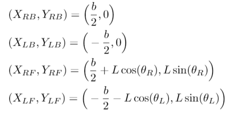
Using the above, we can determine the co-ordinates of the midpoint of the line joining the left and right free joints:

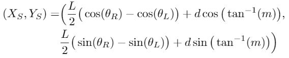
Due to the symmetry of the mechanism, the perpendicular from the striker to the line joining the left and right free joints will pass through the midpoint of the line joining the left and right free joints. This allows us to determine the distance 'd' between the midpoint of the free joints and the striker position, as well as the slope 'm' of the line connecting the two (this will be equal to the negative of the inverse of the slope of the line joining the left and right free joints, as the two lines are perpendicular)


Thus, using the co-ordinates of the midpoint of the left and right free joints and the 'd' and 'm' determined above, we can obtain the position of the striker as follows:
Derivation of dynamics
The relationship between the torque at the joints and the forces at the end effector (in this case the striker) can be determined using the relationship

For our system, the Jacobian 'J' can be determined by differentiating the final equations of kinematics (i.e. the equation governing the position of the striker) with respect to the angles at the two base joints. In other words:


Differentiating the equations we obtain:
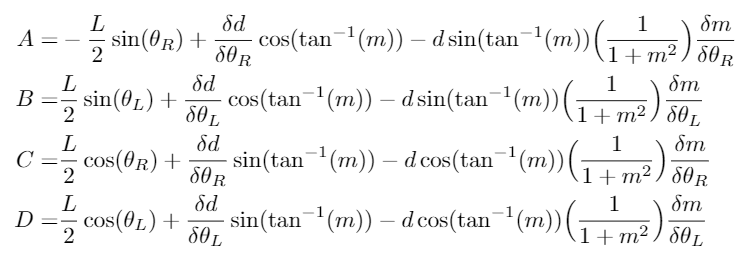
Differentiating and re-arranging the equations for 'd' and 'm' we obtain:

Thus, we have the dynamics of the mechanism.
Qualitative Control Analysis
Puck-Striker Interaction
In software, the time that the puck and the striker remain in contact during collision is typically quite small: on the order of several clock cycles. To provide the sensation of an actual strike, we experimented with several methods for rendering strikes perceptually.
Our initial strategy was to make the striker compliant, allowing the collision to last for a meaningful period and provide force feedback to the user in the vein of a virtual wall. This strategy was successfully in the Haptic Omni assignment to simulate contact between two spheres. In the context of air hockey, however this implementation is less useful. When the colliding objects are approximately the same size, it is easier for them to move through each other, especially when they are travelling through the environment at high speed. Energy leakage can also occur when the two objects are moving at high speed. We found that our sampling rate was too low to provide a stable collision with this model, as the two bodies would clip into each other and then be launched apart unrealistically.
To rectify this, we implemented a constant impulse rendering for collisions during this experiment. The distance between the puck and the player striker is constantly updated in the loop. This distance is checked with a penetration model as in the initial strategy to detect collisions between the striker and puck. However, rather than allowing the puck to be compliant and potentially deposit unwanted energy into the system, we coded a constant impulse value for all collisions. This value was transformed so that the puck was launched in the appropriate physical direction. This was accomplished by keeping track of the angle between the puck and striker in the loop, then add the components of the constant impulse to the final force summation for each loop.
Reference [3] states that such a system was in fact found to be more realistic for the feedback as well. Hence a constant impulse was delivered for the feedback to the user as well but magnified many times over so as to be felt.
Real vs. Physical Walls:
A physical wall was chosen over a virtual wall as the asymmetry in the structure of the pantograph meant that the maximum wall stiffness that could be attained while maintaining stability in different directions was different (the lowest being in the direction closest to the Hapkits). This resulted in a rendered box of play being very unconvincing due to the difference in the stiffness perceived of the different walls of the box.
AI Control Law
The AI control law was a simple PD-type control law. The striker was pulled towards the puck with a force proportional to the distance between the puck and the striker. The spring stiffness was tuned so as to have an appreciable force felt but not be too high that as the puck was moving, the striker was unable to correct for its constantly changing position. In addition to this spring force, a damping force was also applied that was proportional to the velocity of the striker, thus damping out the motion and reducing overshoots.
The stability of the system, in this case, was heavily dependent on the user not letting go of the striker, as if the striker has no external balancing force, it accelerates due to the AI force (whenever it sees the puck close by) to a very high velocity, resulting in the MR sensor losing track of the rotations of the motor and potentially leading to instability.
Gameplay
Of course, players must score during an air hockey game! During the gameplay loop, two scoring regions are constantly checked for the presence of the puck. These areas extend from the edge of the field so that the center of the puck is allowed to enter the active region just before it contacts the back wall of the field. If this center point is found to be the active region, a score is processed. The scoring routine increments the score for the scoring player, pauses the loop for 3 seconds to allow players to prepare for the serve, and then serves the puck to the player that was scored on. When a score of three is reached, the game ends and remains paused until the device is reset.
Our AI goalie follows a simple but energetic routine. It begins in the center of the goal, with the back of the goalie touching the back of the playing field. It then patrols the goal back and forth, reversing direction when it reaches a goalpost. The collision physics for this goalie are identical to those for the player striker, and its position is updated in the dynamics loop as with the puck and striker.
Graphics
As in previous assignments, we chose to use Processing for our graphics interface. The graphics interface consists of several static and dynamics objects which will be discussed here.
The primary static graphics elements were used to display the game field, which remains stationary during gameplay. A single rectangle bordering the entire game window serves as the edge of the field. The rectangle was mapped so that it was coincident with the walls of the field, allowing the puck to bounce off of this boundary. No proxy effect was used here, as the puck/wall stiffness was sufficiently high to provide convincing visual feedback. A smaller rectangle was used to provide a visual representation of the device workspace, similar to the "key" in a standard basketball court. Unlike in physical air hockey, where the user is only constrained by their arm length, our player is limited by the haptic device. This graphics element allows the user to recognize where they are allowed to move, and assuages the frustrating experience of reaching the end of the workspace just before a critical strike. Goals were represented as wide rectangles highlighting the scoring areas of the playing field.
Several dynamic elements had to be displayed during the game's operation, including the position of the player, the puck, and the goalie, as well as the game score. These were printed from Arduino in a tuple that was passed to the Processing interface and updated during every loop:
[x_player, y_player, x_puck, y_puck, x_goalie, y_goalie, player_score, ai_score]
The striker, puck, and goalie are all rendered as circles in the Processing environment. We experimented with proxy effects during the initial penetration experiments, but these proved hard to render at the sampling rate we were using. When we transitioned to a constant impulse model, we removed this proxy effect as it looked more natural. Minor clipping between objects was observed here, but in general the new impulse model allowed us to visually represent collisions with minimal clipping as opposed to the proxy, which would sometimes slip through the player striker.
The score was represented as a series of pips in the corners of the field. Games were played to three, so we found this more satisfying than arabic numerals. At the close of the game, a notification was printed notifying the user of the result ("You Win! :) "or "You Lose! :("), and this notification remained on screen until the device was reset, starting a new game.
Integration and demonstration
The complete demo comprises the mechatronics assembly (motors, linkages, striker, microcontrollers) and the graphics monitor (laptop).
Before the game is started, the difficulty must be adjusted in code. This is done by chainging #define flags at the start of the program; easy mode or hard mode can be implemented, but if no flags are selected, gameplay starts at normal mode. This game difficulty will be in place for an entire gameplay session.
At the start of the game, the striker is placed in the center of the field, and then the microcontrollers are reset. This will cause the puck to be served to the player, beginning the game. Gameplay continues until one side or the other scores, at which point the game will pause for 3 seconds, increment the score, and serve the puck to the player who was scored on.
The game will continue until either the player or the AI scores three points, at which point the game ends and displays a win or loss message. The game will remain in this state until a new game is initiated by resetting the microcontroller.
Results
The base functionality of the system was effective in recreating the feeling of playing air hockey. The combination of virtual environment and force feedback made it easy for users to tell when they had struck the puck, how hard it was struck, and from what direction it had come. Furthermore, the bearings and lightweight components of the linkage made the frictional forces on the striker very low, allowing free space to feel free.
The largest problem with the air hockey system was the fact that the magnetoresistive sensors failed to accurately track quick striker movements. Lateral movement in particular caused the sector to rotate quickly, meaning that when users attempted to quickly move the striker sideways to intersect a moving puck the sensor would not register any motion. This caused the player to typically miss the puck, and also meant that the player's work space was permanently shifted away from its original position. Resetting the Arduino boards was not a viable option as doing so would also reset the score of the game to 0-0.
During demo day users were able to pick up and grasp structure of the game very quickly. The objective and ways to achieve it were clear, and users commented that the collisions "felt satisfying" while playing the game. The largest point of confusion was in the physical and virtual striker motion becoming disjointed due to rapid motion not being picked up by the MR sensor. Users quickly learned to slow down their lateral motions to ensure accurate tracking, but were unable to play the game exactly like they would do with a physical air hockey system.
The additional difficulty settings were successful in following behavior that we coded them to follow. For the 'easy' mode, the striker would snap to the puck if it was approaching from the front. Similarly, for the 'hard' mode there was a noticeable increase in force required to move the striker around the work space. That being said, it is unclear whether or not these difficulty settings actually made the game easier or harder. Some users did not anticipate the magnetic motion of the striker in 'easy' mode, causing them to miscalculate a hit and score an own goal. In 'hard' mode, some users found that the added damping slowed down their motions to the point where MR position tracking became more accurate, enhancing their performance.
Future Work
As described in the previous section, it is currently uncertain whether the 'easy' and 'hard' difficulty settings actual augment/impair player performance. Therefore, the most logical test to run on this system is one that examines the effect the difficulty settings have.
The test would be set up in a format similar to that of Lagemaat, Kuling, and Visell's study on tactile distance reproduction [5]. One trial would consist of a user playing a round of air hockey against a computer-controlled opponent. At the end of this round a metric for their performance would be calculated. Goals scored by the player would make this number larger, while goals scored against the player would decrease the number.
Users would play three trials sequentially, with each difficulty setting (easy, hard, and unaltered) appearing once in a randomized order. Users would not be told which setting was which. This set of three trials would be repeated 5 more times, at the end of which user would be informed of the existence of difficulty settings and asked to label their order in the most recent trial set.
After conducting this experiment with multiple users, average performance for each mode could be calculated for individual users and across all of them as a whole. 1-sided hypothesis testing could then be applied to determine if the 'easy' and 'hard' modes had a statistically significant effect on performance in their intended enhancement direction.
Before conducting this experiment, it would be prudent to make modifications to the system to improve its performance and consistency. The most important modification would be to replace the MR sensors with high-quality optical encoders. These would allow the users to move the striker as fast as they desire without causing position mismatches that result from these motions in the current system. Another useful modification would be to add higher-torque motors to the system. While the current motors are perfectly capable of producing forces high enough to accurately simulate puck-striker impact, they run into problems when attempting to move the striker quickly on its own when the 'easy' difficulty setting is activated. Stronger motors could make this motion less jerky and more consistent across a variety of striker positions.
Our project has applications to any multiplayer virtual environment where healthy competition between all users is desired. If the difficulty settings were changed based on player performance as opposed to manual toggling, they could be used to create an environment that learns its players' individual skill levels and tailors their experience so that no single player dominates over the rest. Specifically this could be useful for motion control based 'party games', video games focused more on creating a fun, competitive environment than precisely representing the skill level of each player.
Files
Virtual environment graphics code (processing)
Arduino code to control mechanism and virtual environment Attach:group12_arduino
CAD for 3D printed parts
References
[1] K. Baur et al., "Robot-Supported Multiplayer Rehabilitation: Feasibility Study of Haptically Linked Patient-Spouse Training," 2018 IEEE/RSJ International Conference on Intelligent Robots and Systems (IROS), Madrid, 2018, pp. 4679-4684.
[2] T. Kosaka, T. Iguchi and H. Noborio, "An impulse-based approach under penetration between bodies for tactile feedback display," Proceedings 2003 IEEE/RSJ International Conference on Intelligent Robots and Systems (IROS 2003) (Cat. No.03CH37453), Las Vegas, NV, USA, 2003, pp. 2684-2691 vol.3.
[3] D. Morris et.al., �Haptic Battle Pong: High-Degree-of-Freedom Haptics in a Multiplayer Gaming Environment� in Proceedings of Experimental Gameplay Workshop, Game Developers Conference, 2004
[4] H. Culbertson and K. J. Kuchenbecker, "Importance of Matching Physical Friction, Hardness, and Texture in Creating Realistic Haptic Virtual Surfaces," in IEEE Transactions on Haptics, vol. 10, no. 1, pp. 63-74, 1 Jan.-March 2017.
[5] J. M. van de Lagemaat, I. A. Kuling and Y. Visell, "Tactile distances are greatly underestimated in perception and motor reproduction," 2018 IEEE Haptics Symposium (HAPTICS), San Francisco, CA, 2018, pp. 301-306.
[6] An, J., & Kwon, D.-S. (2009). Five-bar Linkage Haptic Device with DC Motors and MR Brakes. Journal of Intelligent Material Systems and Structures, 20(1), 97�107.
Appendix: Project Checkpoints
Checkpoint 1: Hardware Design and Assembly
This week, our goal was to design and assemble all of the hardware for the virtual air hockey table. Our apparatus consists of a 5-bar linkage driven by two re-purposed Hapkits, similar to the Graphkit method. This requires a base (to constrain the Hapkits), four linkages, an air hockey striker, and a raised playing field to accommodate the offset between the Hapkits and the table. The base and striker were additively manufactured using an Ultimaker 3, and the linkages were laser cut from 1/4" Duron in the PRL. Sockets were manufactured to ensure that the rear links were able to properly interface with the Hapkit.
The air hockey linkage is designed to provide a workspace taking up approximately an 8.5" x 11" area: i.e. the size of a normal sheet of paper. The striker is scaled down to allow the user to traverse the playing field freely without hitting a boundary.
A design drawing was produced to ensure that the 5-bar linkage has an appropriate workspace for a game of air hockey. The striker is held by collars at the end of the forward links. The rear links are slotted into the existing grooves on the Hapkit sector, and the Hapkit wiring and motors are unaltered from their original design.

Kinematic and Dynamic Analysis of a 5 bar Mechanism
This work was done this week in order to facilitate the development of the software for the haptic rendering for next week and next checkpoint.
A literature survey was conducted in order to determine the most suitable way to analyze the kinematics and dynamics of a 5 bar mechanism. This is crucial as a 5 bar mechanism forms the basis of our haptic device; in particular, a five bar mechanism with two motors at the end of the ground link. Of the several techniques that we encountered, the simplest and most suitable for our case was found to be from the reference http://www.iit.bas.bg/PECR/55/53-63.pdf. This paper provides a technique that allows for the easy determination of the forward kinematics by considering the 5 bar linkage as a combination of two RR mechanisms-a known and well-studied structure. This technique results in a simple analytical representation of the Jacobian (between the input motor angular velocity and end effector linear velocity) and its determinant, thus in addition to the kinematics, we will also be able to determine the force at the end effector due to the actuating motors.
By mechanically constraining our system to be very far from singularities, we can ensure that the Jacobian will always be invertible and hence, use these same expressions to determine the inverse kinematics (i.e. motor velocity) and motor torques to achieve the end effector velocities and forces that we require.
We were able to fabricate and assemble the majority of the mechanism this week, with a couple small setbacks preventing the complete assembly. Our upper links were too long to print in the PRL 3D printers, so we used a combination of a printed socket and laser-cut duron link. The connection between the two proved to be less stable than desired, so we plan on printing the full link on a larger-format printer. We also have yet to acquire the necessary fasteners to connect the upper and lower links, as the set screws and shoulder collars will need to be bought from external sources. Finally, our playing field has not been constructed yet either as the height of this will be contingent on the finalized clearance of the striker, which we will know when the rest of the mechanism is finalized and constructed. Despite these missing components, we fabricated and assembled a functional pantograph mechanism up to the end of the upper links.

Checkpoint 2: Software Design
Mechanism Sizing Validation
Our first task this week was to perform calculations about the sizing of our mechanism with respect to the motors based on feedback we received in checkpoint one. To do so, we performed calculations with our current link lengths of 0.3m to get a conservative estimate for the maximum force that the motors would be able to provide. We found this value to be on the order of 1 N, or about half of the force that our hapkit could deliver to the end of the handle. Given that the majority of our forces will be use for simulating collisions with a puck (which is a relatively light object), and gently influencing user movements to tweak performance, we believe this force value will be sufficient. Full calculations are shown in the image below (typo in picture: should be "when Lm is lowest" in line 2, not "highest"):

Final Hardware Assembly
With the hardware sizing validated, we completed the hardware manufacturing and assembly with new fasteners and lighter, 3D-printed links. The pantograph can navigate the entire planned 8.5" x 11" workspace without running out of range of motion.
Software Development
The kinematics and dynamics of the 5 bar linkage have been computed and implemented as Arduino code. Although we initially wanted to use the simplified Jacobian from the paper mentioned in Checkpoint 1, we realized that this required the value of the joint angles of the free joints of the 5 bar mechanism, which we did not have directly and were messy to calculate. However, due to the symmetry of our mechanism (all non-base links have length of 30cm) and the fact that we are going to constrain the workspace so that we never encounter singularities, and never have the striker move so that we can have multiple inverse configurations, the position of the striker can be computed using basic geometry as a function of the base joint angles. Similarly, the force at the end effector can be calculated as a function of the input torques at the motors.
The dynamics of the puck have been coded in, along with its interaction with the 4 virtual walls of the field, and the striker. The interaction of the striker with the wall has also been included. A simple spring force based on penetration distance between interacting bodies, has been used for the interaction force. More complex force renderings between the puck and striker for more realism and assistive guidance will be experimented with after integration with hardware and inclusion of graphics.
The current code can be found here: Attach:ME327_ArduinoCode_Checkpoint2.txt
Incomplete Objectives
While we have working hardware and individual software components, we were unable to integrate both subsystems before today. This was due to scheduling difficulties as well as the fact that certain hardware components (Duron/PLA hybrid links) failed after the last checkpoint and needed to be re-manufactured to have higher build quality. We plan on integrating on Saturday and add graphics so that we can spend Sunday and Monday programming adaptive difficulty schemes for Tuesday's demo.