

Goodloe Blankenberg Clark

Haptic Teleoperation of a LIDAR-Equipped Vehicle
Project team members: Beck Goodloe, Erick Blankenberg, Josiah Clark
Our project is to teleoperate a robotic vehicle with a 2DoF haptic handle which responds to the environment of the robot as sensed by a mounted LIDAR. We seek to gain an understanding of the benefits and drawbacks of haptic teleoperation and to delve into possible algorithms for enhancing transparency of the system. We plan to use a 5-bar linkage 2DoF haptic stylus as our mode of teleoperation and an X-Holonomic drive system with mounted LIDAR as the vehicle.
On this page... (hide)
Introduction
Mobile robotics has many applications including exploration, search and rescue, and augmented driving. Up until the present the control of these systems has relied heavily on visual feedback from cameras and sensors. Haptic feedback is a way to augment this, providing extra information about the environment to a human operator with applications such as aid in obstacle avoidance[1]. We present a holonomic vehicle remotely controlled via computer keys which relays information about the surroundings such as proximity to objects as detected by a mounted LiDAR. The primary goal of this project was to design and create a network capable of handling such large data streams and bilateral control between a vehicle and the controller.
Background
While this project had several components including extensive hardware design, the majority of our research focussed on the construction of the bilateral communication network. One of the papers that really influenced our design was written by Pecly et. al and entitled “Model Reference Model-Mediate Control for Time Delayed Teleoperation Systems”[2]. In this paper, the authors discussed several different models for dealing with both the latency and stability of a teleoperated system. Though this will be discussed in depth in the Methods section of this report, this paper encouraged us to design a data driven control system completely contained within the parameters of the haptic device to ensure stability.
Methods
Hardware Design (Drive Base)


While hardware design ultimately appeared to be a large part of our project, it didn’t consume the majority of our time. Entering the class, all three members of our team had experience with mechatronics as well as a wealth of general electronic components. Combing our resources and knowledge, we were able to repurpose the base of one of our members ME210 project and modify it to suit our broader needs for this project. The general layout is as follows:
- 4 omni wheels capable of driving/rolling in both the x and y axes.
- NiMH batteries at ~14V providing power to all systems.
- An array of buck converters stepping down the operating voltage of the batteries to suit the needs of various other electronic components.
- 3 microcontrollers/timers handling various sensors and data processing.
- 4 limit switches with hinged bumpers for physical obstacle proximity detection.
- 2 L298N motor drivers capable of handling the PWM signals and power of all four wheels.
- 1 RaspberryPi handling wireless communication and data packing for LIDAR system.
- Slamtech RPLIDAR with associated microcontroller and driver board.
Beyond the electronic components listed above, all other framework and construction was done with Ľ” and ⅛” laser cut duron.
Hardware Design (Hapkit)

In the early stages of our project, we intended to also design our own 2 DoF haptic device was scratch that had a higher stall torque and thus would render stiffer walls. In this stage of the design, we chose motors with a 128:1 gearbox that would give us the required torque at the expense of transparency. We were not, however, concerned with the loss of transparency because the built in resistance and damping would simulate the resistance of a gas pedal in a car for example. The motors we also chose had an encoder resolution of 0.5˚.
As we began to dive into the project we realized how overscoped this project was. Compounded with the fact that flooding in Ohio delayed the shipment of our motors by 10 days, we were forced to pivot in order to get a working prototype. Using a design created by members of the CHARM lab, we combined two of our Hapkits into the Graphkit seen below.

Using this device, we were able to create a functional prototype with all elements of the project functioning as they should. As the due date approached and we delved deeper and deeper into the design of the bilateral communication network, we realized that this early prototype would end up being our final iteration.
Functionality Overview
The purpose of this section is to give the reader and overview of what this system actually does before delving into design considerations that led to the final product.There are many different systems in this project that all contribute to the overall functionality. In order to get an idea of how each one of those works, we will follow a single packet of data and see how the system interprets it.
The packet begins at the LiDAR system where the surrounding environment is scanned and stored in a map holding the absolute direction as a reference to the magnitude of the free space in that direction. This pack is then send to the Raspberry Pi on board the drive base. From there it is sent to the master computer where it is converted into a visual map of objects around the vehicle and displayed to the user. From there, the user can change the “direction” that the haptic device is “looking”. Based on the current direction that the device is looking, the packet is converted into a vibration frequency value and send to the Graphkit. The Graphkit then vibrates at this frequency, haptically informing the user of the relative distance of the object in the direction the device is looking.
This system could be used a variety of ways. The most informative way is by having the vehicle enter a room and remain stationary. The user can then scan through all 360˚, feeling variable frequencies of vibration as they do so (faster vibrations mean the object is closer and vice versa). After haptically obtaining an idea of where the objects are in the room, the user can then move in a direction that is free of obstruction and repeat the process again. This allows the user to gather information about the surroundings without actually being there or seeing them.
A short video of us finally getting the system working can be seen here: https://www.youtube.com/watch?v=GCyLYBwdMbQ&feature=youtu.be
System analysis and control
LiDAR
The first big challenge of the project for us was creating a system for recording, processing, and transmitting the data collected from the LiDAR. To do this, we mounted a Pi3 on the drive base connected to a LiDAR . This Raspberry pi was responsible to decrypting the packets output from the LiDAR into usable information. We chose to format this information as a 2-dimensional array with the first index holding the absolute angle and the second index holding the magnitude of clear space in the direction of the associated angle. We achieved this processing by building on a Python script written by Michal Adamkiewicz, a member of the Stanford Robotics Club and friend of the team.
Bilateral Communication
Reliability of communication proved to be one of the largest challenges we faced in the project. After processing the LiDAR information on board the drive base, the Pi3 was then responsible for packing that data into the form of a UDP packet. User Datagram Protocol packets are a way of compressing and transmitting data in a semi-reliable fashion. We chose to use UDP over TCP (Transmission Control Protocol) because UDP is connectionless, meaning that the receipt of data by the host is not tracked, making the system faster, albeit less reliable. This is discussed in further detail in the Study section. These UDP packets were then transmitted over a static IP hosted on a Hamachi network that both the master computer and the Pi3 were connected to. The host computer was then able to unpack the UDP packet and have all of the most recent LiDAR data for further, more rigorous processing.
The other form of bilateral communication in this project was the link between the master computer and the Graphkit. Because we did not have any more Raspberry Pis available to use and because the Graphkit itself was not moving, we opted for a wired connection between the two. Over Serial in the USB connection, the master computer was able to directly transfer the important information Hapkit.
Data Processing
After the wireless bilateral communication issue, the most challenging part of this project was filtering the LiDAR data into a responsive, continuous datastream. We achieve this a variety of ways. Because the UDP packets were unreliable, we knew that each packet of data could be missing data at certain degree measurements, or have all the data lost entirely over the course of a single scan. In order to combat this, we created a storage system with persistive memory. Essentially what this means is that as new LiDAR data comes in, filter and process only the points with uncorrupted data. We then created a complete 360 degree model with the partial data over a consistent interval by using a nearest neighbor approximation to existing data points to create a continuous image across all 360˚ at two degree increments. This image was then time-stamped and added to persistive memory. This persistive memory system kept a record of every continuous time-stamped dataset and applied a low-pass moving average filter to the data, synthesizing the images into a single representative model. With high frequency noise entirely eliminated.
Stability
In the initial stages of our design, attempted to not only give the user haptic feedback through the Graphkit, but also teleoperate the the vehicle with the Graphkit as well. As we built prototypes for this system, we found that the latency in the Serial communication created massive instabilities that would only allow us to render resistance up to spring constants of about 25 N/m. In order to limit the effect of communication latency, we decided to separate the control device from the feedback device. This allowed us to pass far less data to the Graphkit, increasing not only the stability of the system, but also the reliability of the information. Furthermore, this allowed us to process the data slightly differently. Now that we were only passing information about haptic feedback to the device and ignoring information passed the other direction about the handles position and current torque, we could clip the data to fit within the stability of the haptic device. In other words, we could add hard limits on our data that would prevent the Graphkit from ever becoming unstable. To do this, we experimented with spring constants and found the upper bound of stability to be about 300 N/m. We then arbitrarily decided that the lower bound should be 100 N/m because we knew we wanted some baseline resistance to movement. After defining this range of stability, we were then able to linearly map the range of magnitudes output by the LiDAR across the range of stable spring constants, ensuring that the feedback would always be stable.
Study
The study we performed over the last 3 weeks involved the speed with which we were able to achieve bilateral wireless communication between the master computer and holonomic drive base. This study involved weeks of design, testing, and redesign, moving through a number of systems and structures before landing on a final one. Each design iteration is listed below:
- We originally designed our network to pass information in the form of TCP (Transmission Control Protocol) packets from the LiDAR to the master computer. These were then unpacked and directly updated the current values of the object detection model. This system did not account for mistakes or lost data and gave us a very poor resolution image, though it was quite fast, updating at about 4 frames per second or 4 Hz.
- In order to improve the resolution of the image, we applied a series of low-pass filters to make the information continuous and stable. Though successfully improving our image, the processing of the data slowed down communication and occasionally overflowed the buffer, resulting in an update rate of about a frame every 2 seconds or 0.5 Hz.
- After doing extensive reading on the subject of TCP systems versus UDP systems (User Data Protocol), we decided to make the switch. What we found was that TCP was designed to be a very reliable form of communication, also known as “connection oriented”. This means that each packet is not only passed to the host, but the host sends back confirmation that the packet was received and a snippet of the unpacked data so the sender knows it wasn’t corrupted. While this kind of connection is very important for applications where reliability is of foremost importance, it is much slower than UDP. UDP prioritizes speed over reliability, often being used for things like wireless voice communication where small loses in data don’t render the system useless. The result is much faster communication. After switching to this system, we were able to get our refresh rate back up to about 3 Hz even with the low pass filters in operation.
- The last leap that we made was data interpolation. In the original system, we only updated what the user saw once a continuous, new image had been completed. This meant that the data the user saw only refreshed after every single degree had been updated from the LiDAR. The problem with this was that with corruption and lost data, it too a relatively long time to get a complete image. To fix that, we implemented a piece of code that interpolated between known points to fill in gaps on every LiDAR sweep. This meant that we could now refresh what the user saw with the newest data before a complete image was rendered. We then implemented a moving average so that gaps or errors in the interpolated data wouldn’t dominate the output. This version was our final iteration and achieved a refresh rate of 12 Hz.
Results
This project did not end up exactly as we desired it to, but we are proud of it all the same. After a couple of pivots, we ended up with the system described above that could be used to map and move through environments in situations were humans may be unable to move or is unsafe for entry.
In summary we successfully created a s system that could wirelessly control a vehicle with a mounted LiDAR, process that LiDAR data, wirelessly communicate it back to a master computer, convert that data into a 2-dimensional visualisation of the room, and pass that information to a haptic device that informed the user about obstacles in the way of the vehicle.
The biggest problem with the results of this research project was the reliability of the network we designed, though we primarily attribute those failures to the Stanford network’s disdain for VPNs and non-functional USB ports.
In general, the feedback we received at the open house was positive. The primary comment we received was the the system was not very intuitive to use (though users picked it up quickly). The primary reason for this is likely because the haptic feedback was split from the wireless control of the vehicle in order to make this project feasible. A solution to this, though not feasible to us over the course of this class, is discussed in the subsequent future work section.
Future Work
Future work on this project by us and other would be simply achieving the functionality that we originally dreamed of. This would primarily involve designing our own 2 DoF haptic device with higher stall torque and higher, more reliable encoder resolution. This would allow us to not only drive the vehicle using a better haptic device, but also render the LiDAR information in a slightly different way. What we originally dreamt of was creating a 2 DoF haptic device that was self centering with a baseline stiffness of about 100 N/m. As the user moves the handle away from the origin, we can use the Jacobian model to calculate the magnitude and angle of where the handle is relative to the origin. This would then directly control the direction that the vehicle is driving using PWM to control speed and taking advantage of the holonomic drive base with omni wheels to drive in directions other than directly along the x or y axes. Based on the direction that the user is driving, we would then be able to render a spring pulling the user back to the origin as a function of how close the user is to objects in the direction that it is driving. What this would effectively serve as is active collision avoidance that updates quickly based on the direction the user is driving.
Acknowledgments
Special thanks to professor Okamura, the teaching staff, the many people in the PRL who helped us along, and our classmates for their support.
We would also like to thank Michal Adamkiewicz and the Stanford Robotics Club for providing the RPILiDAR A2 used and help with the low-level processing of the LiDAR data.
Files
All code can be found in the following repository, we wrote 709 lines of code for this project: https://github.com/Eblanken/Classes_ME327_HapticBot.git
The CAD files for the robot can be found in this Onshape document: https://cad.onshape.com/documents/40d99b23721eb194660a2746/w/a12e123b72e9b393c50b7328/e/9a90a2f387e22283b39ff1ef
References
- Lee, Sangyoon, et al. “Haptic Teleoperation of a Mobile Robot: A User Study - Semantic Scholar.” Undefined, 1 Jan. 1970, www.semanticscholar.org/paper/Haptic-Teleoperation-of-a-Mobile-Robot%3A-A-User-Lee-Sukhatme/09d0adc2097ce423bbb61c35a7e49d4dfa3f65d2.
- Pecly, Leonam S.D., et al. “Model-Reference Model-Mediated Control for Time-Delayed Teleoperation Systems - IEEE Conference Publication.” IEEE Explore, IEEE Haptics Symposium, 10 May 2018, ieeexplore.ieee.org/document/8357155.
Appendix: Project Checkpoints
Checkpoint 1
For this first checkpoint, we focussed on the individual elements of our system and got them working. We connected the LIDAR to a computer and wrote a script to graphically display spatial information on a screen.


We hacked an old ME210 robot with an X-Holonomic drive base and are able to control it with keyboard arrows.
Finally, we built a GraphKit from two of our team members’ HapKits and some additional parts. We integrated these elements together as seen in the diagram below. Our next step is to optimize response time and develop an algorithm for the haptic handle responding to the sensor data.

Checkpoint 2
Over the course of this last week, we have been focussing on primarily optimizing components specific to each component of the system.
Teleoperated Vehicle
The issue that has been plaguing us here is latency. In our original design, we were using TCP packets to pass LIDAR information over a static IP hosted on the raspberry pi mounted onto the drive base. TCP packets are designed to be the most reliable form of wireless communication with several checks and double checks to make sure that all the data is getting to the right place and then confirming receipt with the sender. Using that system, we were operating the system at a rate of about .5 Hz. This meant that we were getting a new LIDAR image every 2 seconds. Quickly we realized that all of these double checks were not necessary for us and that we wanted to prioritize reducing latency. To do this, we switched to UDP packets which are faster, but prone to dropping information. Since the host computer would save a record of what the most recent LIDAR information is, we didn’t care all too much about losing packets. If a packet was lost, the old value would simply persist until the next packet arrived. Using this system, we are now operating at 12 Hz. This means we get a new LIDAR image every 83 ms.
Video of improved teleoperation:
https://www.youtube.com/watch?v=kevJE2CHaks&feature=youtu.be
LIDAR System
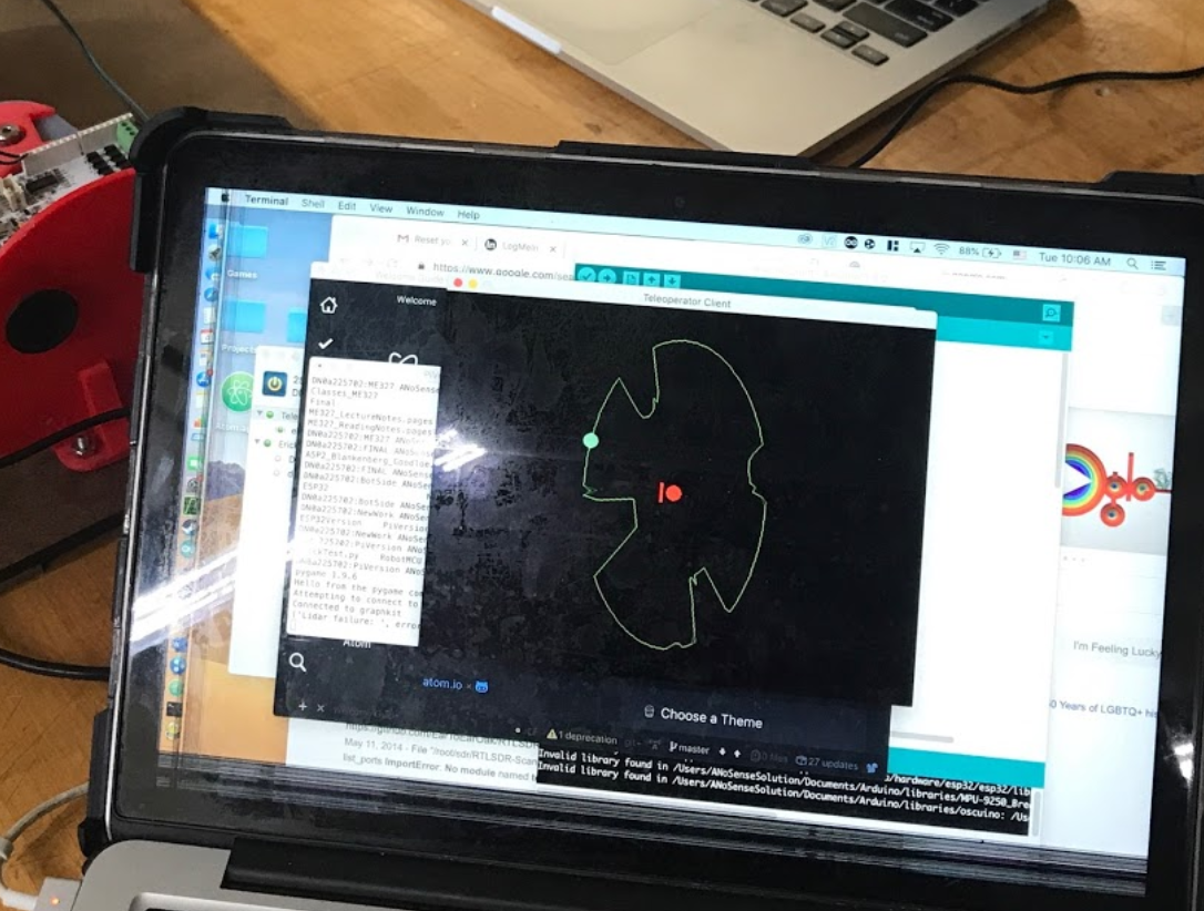
The LIDAR system is also using the same UDP packet organization as described above with a very similar functional frequency. Below you can see the updated, faster visualization that we will spend the next few days integrating.
https://www.youtube.com/watch?v=_HPYG42b6mE&feature=youtu.be
2 DoF Haptic Device
This system has been giving us some issues as we have spent more time focussing on the latency of the teleoperated system and less on the construction of the 2 DoF haptic device. Over the past we have been using a modified GraphKit system with a stiff base for testing. We are also currently building a method for weighing down the entire device so that the user can impart more force onto the controller without moving the entire unit.
It looks like, based on time constraints and availability of PRL resources that we will continue to use our modified GraphKit through the final demonstration.
Integration
This is now our biggest focus → making sure all the systems work together. Currently, we can plug our GraphKit into the master computer and calculate its force and position using the calculated Jacobian from class. Over Serial(), we can then pass that information into a Python program that interfaces with the LIDAR so that all of the information is now in one place.
By Sunday night we would like to be able to drive the car with the haptic device running a self centering program.
By Tuesday morning we would like to add modulated feedback control on the device as a function of the LIDAR data and current position of the controller.