

Group 16
A study of visual vs haptic cues for maze exploration using pantograph position tracking
Project team members: Amar Hajj-Ahmad, Dane Brouwer, Brian Vuong, Thomas Lee
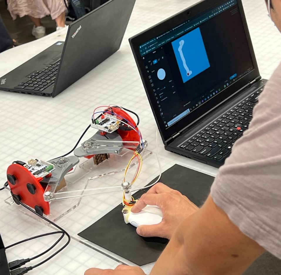
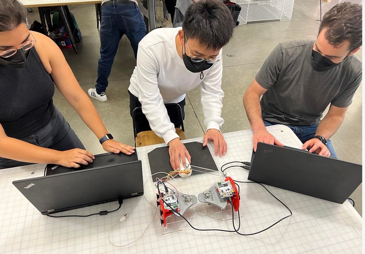
Visual and blind maze being solved during Demo Day.
Our project seeks to understand how well haptic feedback via vibrations can substitute visual cues in how fast users can complete virtual mazes. We utilize a pantograph assembly to compute user position, and eccentric rotating mass motors (ERMs) to provide vibrotactile feedback upon hitting the walls of a maze.
On this page... (hide)
Introduction
The design of our device utilizes the kinematics of a pantograph coupled with two Hapkits. The study will include a reference to literature on the kinematic equations of a 5 bar pantograph, resulting in a workable area for user interaction, and viable position tracking for simulating the virtual blind maze. In addition, the study will test the relationship between vibrational feedback and proprioception. The intent is to simulate a virtual maze, and study the importance of visual cues versus haptic cues. We will conduct user testing to compare the two types of assistance in successfully completing the given exploration task.
Background
In this section, we look at publications that studied pantograph design and kinematics as well as the study of haptic feedback to enable non-visual navigation of virtual scenes.
In [1], researchers studied the effectiveness of utilizing kinesthetic rendering to produce accurate tactile signals that correspond to various textures. The device used is a 5-bar pantograph, which is a two-degree of freedom parallel mechanism that sends tactile feedback to the user. The main components of a pantograph include linkages to determine the workspace, motors to apply torque, position sensors to keep track of where the user is, and a microcontroller to allow the components to communicate with each other. The forward kinematics used throughout this report draw heavily from the equations presented in [1].
Prior work has also investigated the ability of haptic cues to assist the navigation of virtual mazes. For example, the authors in [2] created a virtual maze with an emphasis on providing kinesthetic stimulus to users to see how it affected navigation capabilities in virtual environments. Specific haptic cues can allow the user to better understand the virtual environment and allow them to navigate a maze using key features such as elastic contacts (walls or floors), textured walls (to differentiate walls and floors), or environmental viscosity (linear opposition when navigating). Furthermore, the authors in [3] instrumented a white cane to generate kinesthetic haptic feedback in virtual reality to enable blind participants to navigate virtual obstacles and in [4], a dual pantograph setup was used to enable blind participants to play video games.
Methods
Below we discuss hardware design and implementation, kinematics and dynamics of the device, perceptual effects rendered, a control analysis of the device, and the final hardware integration and demonstration.
Hardware design and implementation
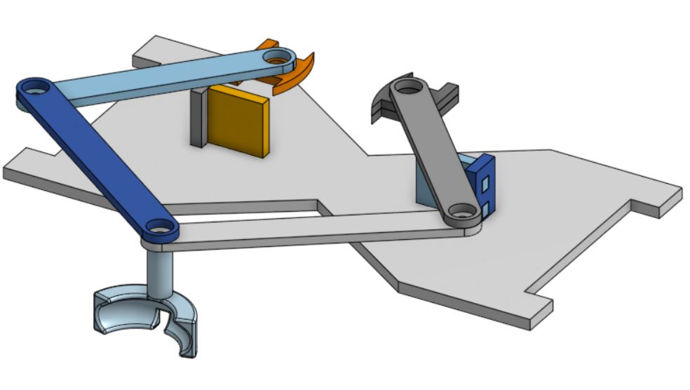
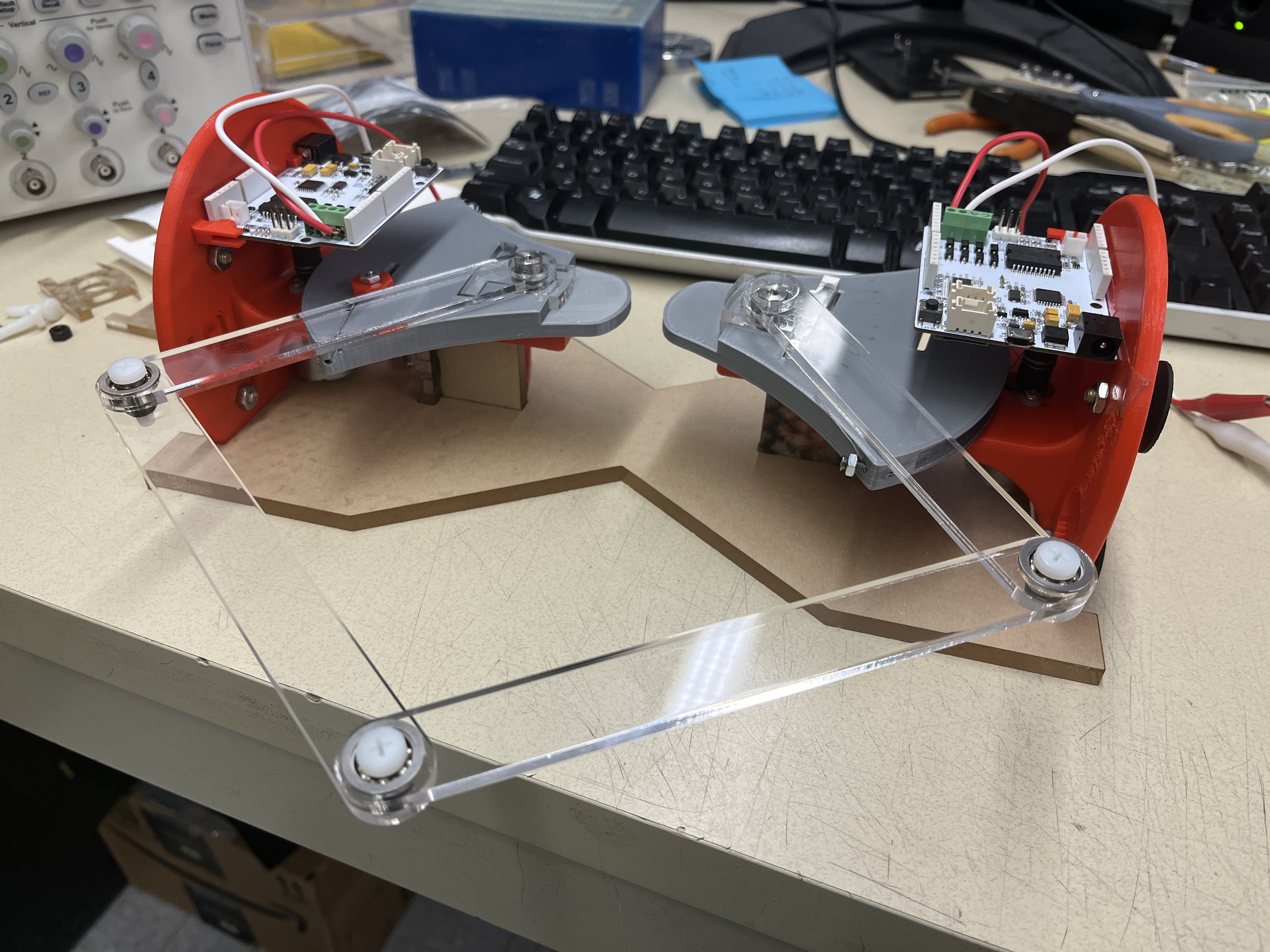
Our main pantograph assembly consists of a five-bar linkage system that generates a 2 degree of freedom system. The mechanism is comprised of laser cut pieces of acrylic which allow for rapid prototyping and quick variations in link lengths to achieve a viable workspace. They connect two Hapkits, and the output of the pantograph (where the end effector is) is connected to a computer mouse allowing the user to operate the same setup for both the visual and the blind maze tasks. Additionally, we connected two ERMs to the mouse as our main haptic feedback source. Magnets on the motor shaft and magnetoresistive (MR) sensors provided to us with the original Hapkit devices are used for position calculation.
Users explore a maze with the goal of reaching the end zone. Users do not know the shape of the maze or have any idea of where the end zone is. Navigating the maze consists of the user moving the mouse with ERMs attached. In the case of the vision-assisted component, a user will erase a top layer of the maze and uncover walls as they go. In contrast, while performing the blind portion of the task, hitting a wall of the maze will cause the ERM to vibrate, indicating to the user to back off and try moving in a different direction.
Kinematics and Dynamics
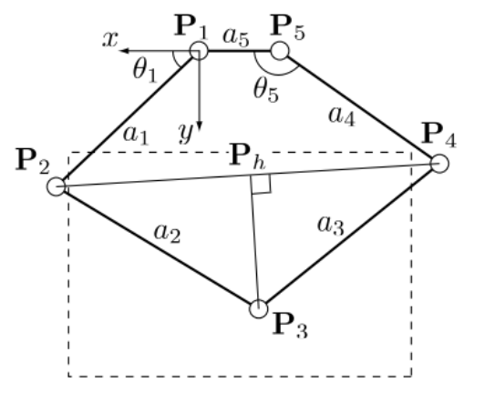
(Source: Campion et al., 2005)
The figure above shows the relevant geometry of our pantograph. The joints are labeled from 1 through 5, and we can use direct kinematics to calculate x3 and y3 from angular data taken at P1 and P5. All positions are measured with respect to the frame centered at joint 1. Links 1 and 4 have a length of 127.1 mm, links 2 and 4 have a length of 152.1 mm and link 5 (distance between link pivot points 1 and 5) has a length of 72 mm. The code adjusts for the relative measurement of the angles from the Hapkit, using the same calibration done in previous assignments in the course.
Demonstration / Application
The demonstration begins with a quick explanation of the rules and goals. The goal is to reach the end zone on a virtual maze, for which the user does not know the shape of the maze or the location of the end zone. Users are timed, and a leaderboard is created to see who can complete the maze in the least amount of time. Users will first complete the visual maze, which does not provide haptic feedback. Users will start at the designated starting point marked by a red dot on the computer screen, uncover the walls of the maze as they move the mouse by erasing the obscuring layer, and end once they reach the designated end zone marked by a green star.
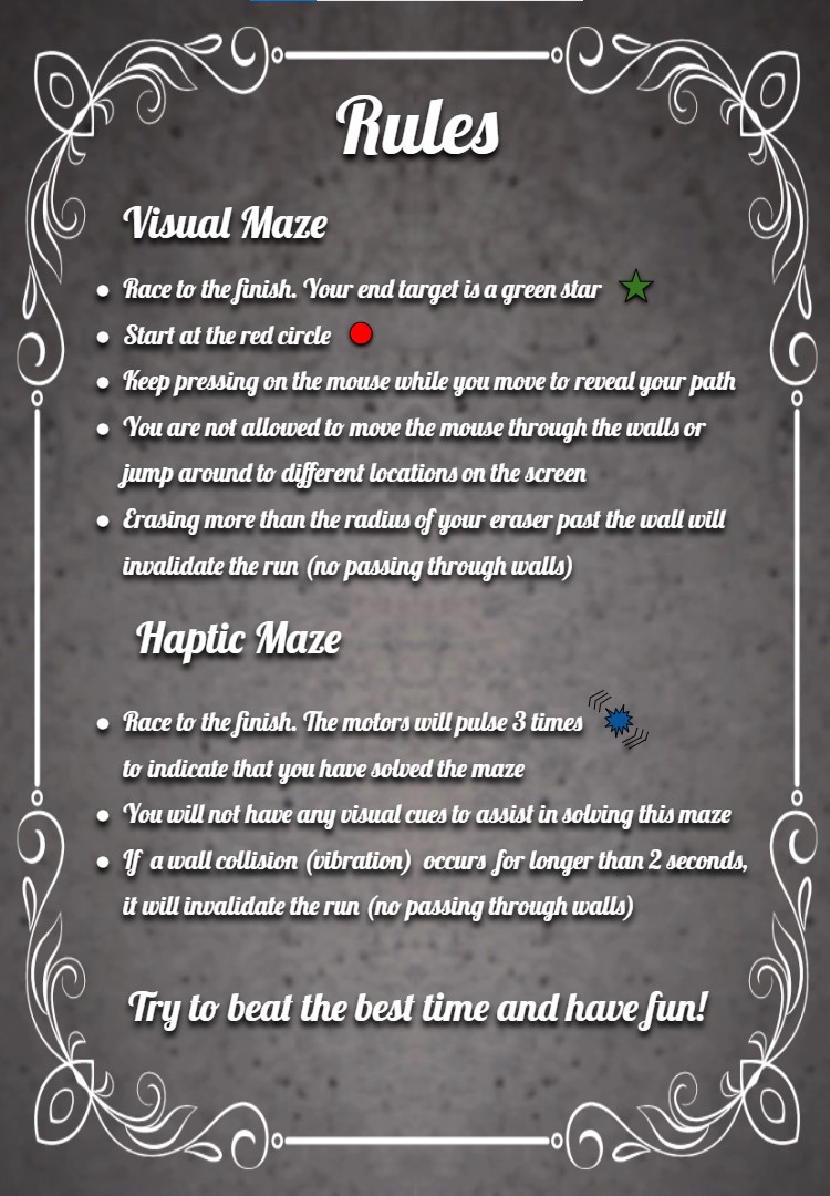
Instructions and rules for solving the mazes.
Once users have completed the visual maze, they will move on to the blind maze with haptic feedback. The experimenter will program the appropriate maze onto the Hapkit board, start the provided teleoperation python script to communicate sector pulley angles between the boards, and move the mouse cursor to the starting point (marked on the rubber mat). To discourage users from completely penetrating and just moving through the walls of the maze, users are instructed that any vibration lasting more than 2 seconds results in a failure of the maze game. The user will feel a 3-pulse vibration sequence upon reaching the end zone.
We have two maze designs that have both been implemented on the visual and haptic sides. Users will do one maze for the visual setup and the other for the haptic setup.
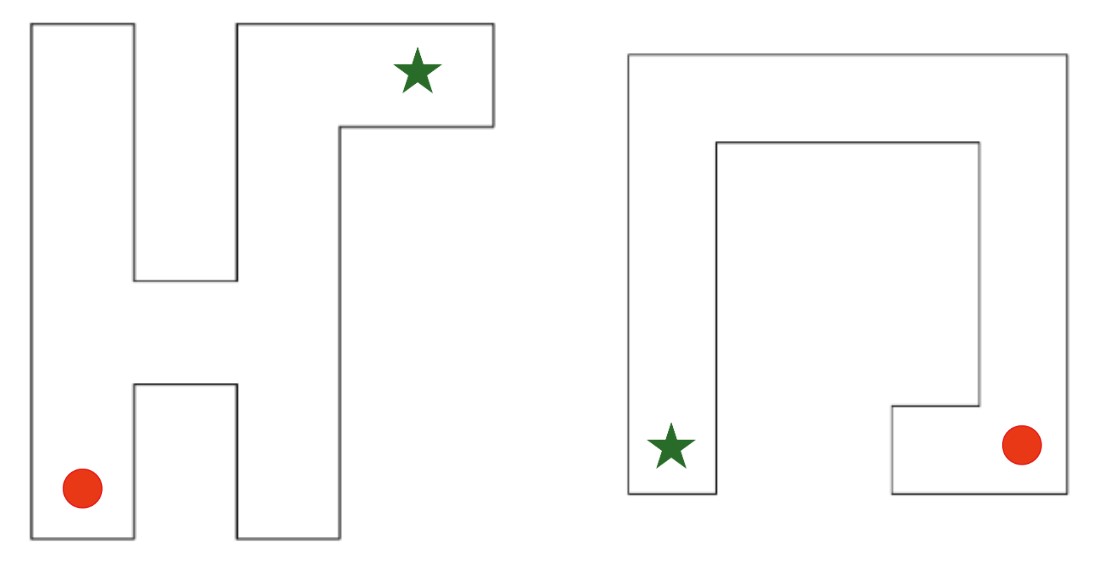
Horse (left) and horseshoe (right) maze patterns.
Software
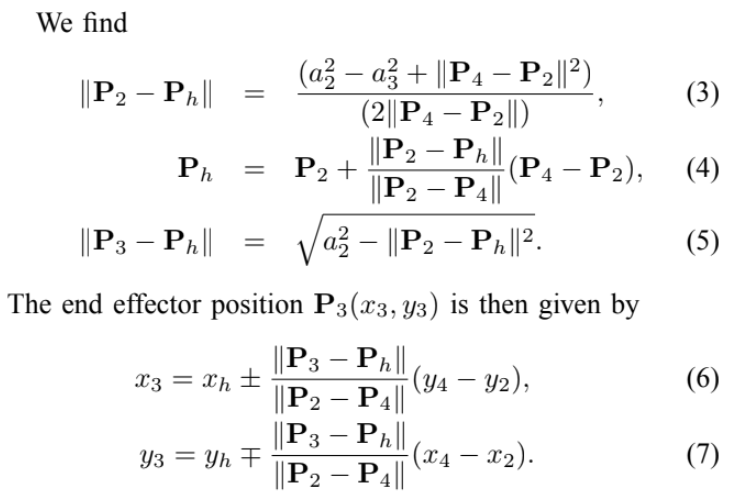
Our software combines joint angle calibration, communication of joint angles between Hapkits, positional calculations according to equations (3) - (7), conditional statements to determine the bounds of the maze, and motor commands to create the haptic cues for the virtual maze.
Voltage output readings from the MR sensor are converted to sector angle and handle position using the Hapkit board starter code provided to us through the course and the calibration accomplished earlier in the course. Serial communication via the hapkit_teleop.py Python module was used to relay handle positions of the left Hapkit to the right Hapkit board, and these handle positions are then converted back to sector angle on the right Hapkit board. Theta1 (t1) and theta5 (t5), as defined by Campion et al., are calculated from sector angle and a rigid angle offsets determined with the Hapkit sector angle at neutral position. Using the direct kinematic equations provided by Campion et al. and our link dimensions, we calculate the various joint positions and ultimately get the cursor position at point P3 in real time.
Our code utilizes counter incrementation and delay functions to create time windows for position calibration. Upon programming or resetting the microcontroller board, we reset the cursor position so that the Hapkit sector angle is at neutral position for initial MR sensor reading calibration. A vibration indicates that initial calibration is complete and the cursor can now be moved to the maze starting point position. The code will then save the current P3 reading (x3, y3) as x and y coordinates of the maze starting point position into module-level variables (x_i, y_i) during the second time window. Once the maze starting point position has been saved, a second vibration will indicate that the user can start moving the cursor to solve the maze.
Through a series of conditional statements, the code checks if the current cursor position is within the bounds of the maze hallways. Locations of the maze walls are all defined in relation to the maze starting point position (x_i, y_i) that was saved earlier. If the cursor is within the maze hallway, vibrations are turned off. When the cursor position is outside the defined hallways (i.e. has penetrated the maze walls), then vibrations are turned on. Vibrations of the ERM are produced with pulse width modulation (PWM) signal using Arduino's analogWrite() function. If the cursor position falls within the bounds of the maze's end zone, three vibration pulses are produced and the void loop is exited to stop further vibrations.
Results
During the demonstration day, we ran our experiment on 15 different users. On average, users completed the visual maze faster than blind maze with haptic feedback. The average amount of time it took to complete the blind maze with the haptic feedback was 66.54 seconds, whereas the average time to complete with the visual setup was 37.0 seconds. However, due to the limited sample size of 15 users, there was large variation in completion time among the users. We also found that it took a longer time for users to solve the horseshoe-shaped maze as compared to the horse-shaped maze under the haptic feedback setup. Despite the users having no prior knowledge of the two maze patterns, we suspect that participants completed the horse-shaped maze more quickly because they tended to expect the maze to start and end in opposite corners of a rectangular workspace, as with the horse-shaped pattern, rather than on the same side, as with the horseshoe shape. It is also unclear as to whether having every user start with the visual maze, as opposed to randomizing the visual and haptic setup order, resulted in any biases in their approach to navigating the maze.
Multiple users noted that they experienced difficulty remembering which direction they were moving in before hitting a wall with just small movements of the hands and triggering a vibration. Other users also noted having difficulty recognizing the 3-pulse vibration sequence upon reaching the end point. Since there was no visual display of the users' path during the haptic setup experiment, it was difficult for the experimenters to confirm whether users had completely penetrated the virtual wall and cut corners to move from one maze hallway to the other. These observations point to some drawbacks in our design that could be addressed in future work.
Future Work
Based on user feedback, there were a few points in our design that can be improved on. Firstly, the indication of reaching the end point should be more noticeable, as it was difficult for users to distinguish between the 3-pulse vibration sequence and vibration from hitting a maze wall. Future iterations could use a different type of feedback, such as some audio or visual display, to indicate the user has finished the maze. Users also suggested that we incorporate directionality into the vibrotactile feedback to assist with navigating the maze. For example, using multiple ERMs attached to different locations of the mouse, users would be able to determine which side of the maze hallway they penetrated based on the location of the vibration. Given more time, we could also design the pantograph as an impedance control device where the user would receive force feedback upon penetration of the virtual walls. Rendering stiffness of the virtual walls would prevent users from cutting corners while navigating through the maze.
Files
Arduino and Python code: Attach:mazecode.zip
Materials list: Attach:hapkitpartslist.pdf, Attach:solidworksfiles.zip
References
(1) Campion, G. (2005). The Pantograph Mk-II: A Haptic Instrument. In: The Synthesis of Three Dimensional Haptic Textures: Geometry, Control, and Psychophysics. Springer Series on Touch and Haptic Systems. Springer, London. https://doi.org/10.1007/978-0-85729-576-7_3
(2) Cervantes, Gabriel & Parra-Vega, V. & Domínguez-Ramírez, Omar. (2008). Haptic Cues for Effective Learning in 3D Maze Navigation. 93 - 98. 10.1109/HAVE.2008.4685305. https://www.researchgate.net/publication/224352632_Haptic_Cues_for_Effective_Learning_in_3D_Maze_Navigation
(3) Alexa F. Siu, Mike Sinclair, Robert Kovacs, Eyal Ofek, Christian Holz, and Edward Cutrell. 2020. Virtual Reality Without Vision: A Haptic and Auditory White Cane to Navigate Complex Virtual Worlds. Proceedings of the 2020 CHI Conference on Human Factors in Computing Systems. Association for Computing Machinery, New York, NY, USA, 1–13. https://doi.org/10.1145/3313831.3376353
(4) Oliver Schneider, Jotaro Shigeyama, Robert Kovacs, Thijs Jan Roumen, Sebastian Marwecki, Nico Boeckhoff, Daniel Amadeus Gloeckner, Jonas Bounama, and Patrick Baudisch. 2018. DualPanto: A Haptic Device that Enables Blind Users to Continuously Interact with Virtual Worlds. In Proceedings of the 31st Annual ACM Symposium on User Interface Software and Technology (UIST '18). Association for Computing Machinery, New York, NY, USA, 877–887. https://doi.org/10.1145/3242587.3242604
Appendix: Project Checkpoints
Checkpoint 1
Our goal for this checkpoint was to complete the fabrication of hardware needed for the project. We have managed to complete a first working iteration of the system, which we modeled in CAD and created using laser cut pieces. So fine tuning of the link lengths might still be needed moving forward, but this allows us to start programing and testing our algorithms leading up to the final project.

Sketch for both the visual and haptic setups during our brainstorming session.
Checkpoint 2
We have designed the blind maze patterns and created the visual representations for them. Using Campion et al. 2005 as a reference, we defined the direct kinematics of the pantograph and implemented the Arduino code for tracking the position of the end-effector (mouse cursor). We then proceeded to implement the code for creating regions with and without vibrations for our maze patterns. Further adjustments to the dimensions of the mazes will be made in the following days as we conduct more user testing and ensure that the maze is discernable within the workspace.