

Group 20
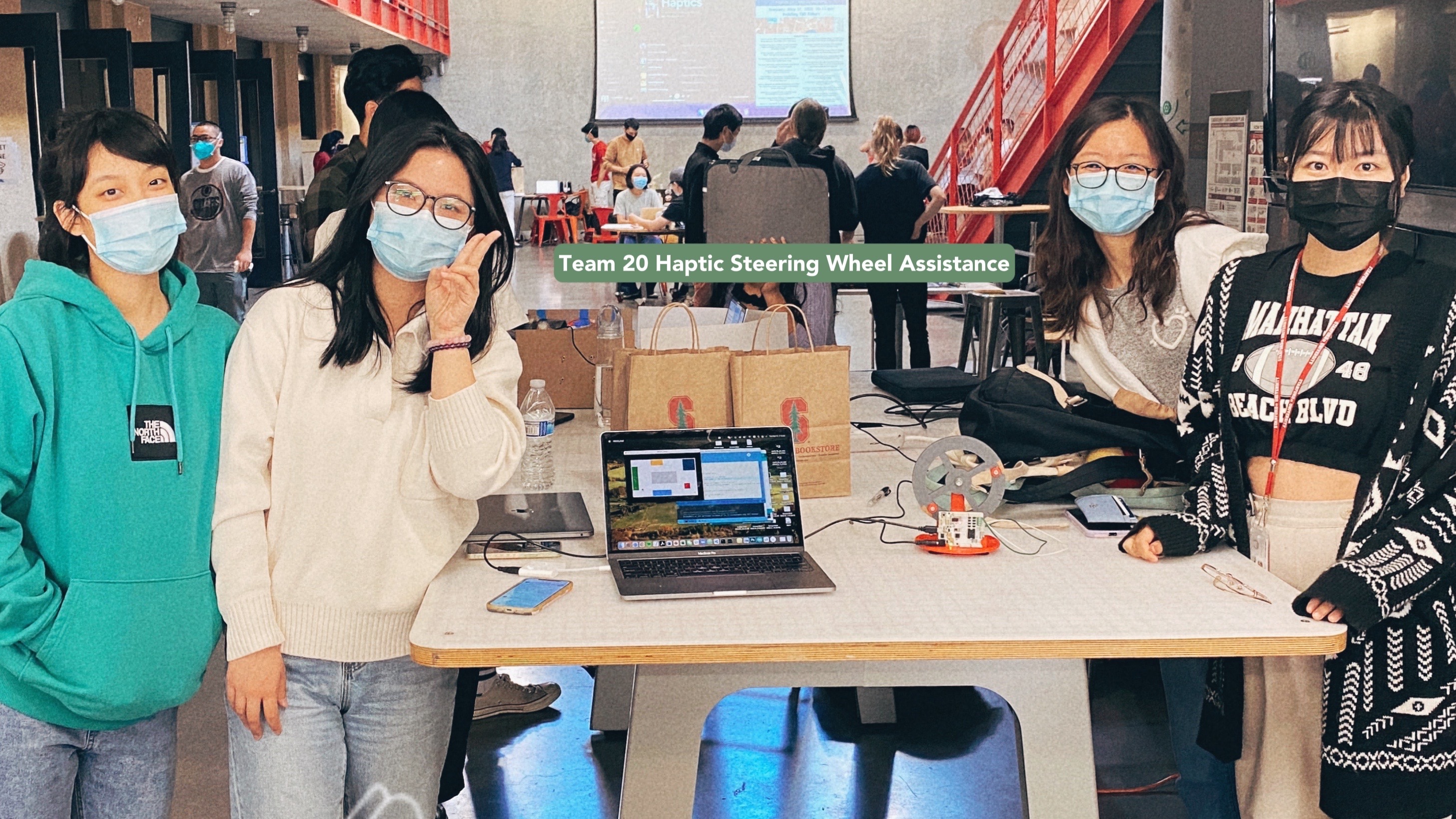
Haptic Steering Wheel Assistance
Haptic Steering Wheel for Autonomous Driving
Project team members: Yafei Fan, Zhuzhu Wang, Kexin Weng, and Kexu Zhou
Research development of autonomous driving has seen a boom in the past decades. Inspired by the haptic applications in autonomous driving, we aim to build a topology of the driving environment with designed barrier walls. We simulate the experience of driving a car with a haptic steering wheel to achieve some level of autonomous driving. The realized product can help people get outside of the obstacles with an instructive force on the wheel. Without a driver, the wheel would also be able to steer steadily and automatically to avoid getting stuck after bumping into the wall. The completeness of the project is 100% and future directions are proposed.
On this page... (hide)
Introduction
With the fast iterations of learning tools, autonomous driving as an interdisciplinary field has attracted thousands of talents to compete in the markets over the recent decades. As the definitions of vehicle autonomy and security are enriched, we are obsessed with the idea of embedding haptic control into the autonomous system. Therefore, after getting exposed to the domain knowledge and hands-on experience in previous homework, we became motivated to design a system that simulates the driving environment. We can use a 3D printed steering wheel attached to our hapkit device, where we can manually steer the wheel to give input to the system, and in the meantime, we are able to receive forces from the wheel to achieve instructions and autonomous steering.
The expected outcomes of our system are described as follows:
1) We will 3D print a steering wheel that got attached to our haptic device, whose magnetic sensor can detect the angle of the wheel angle. We should be able to steer the wheel and drive the virtual car to take turns.
2) The driving speed of the car and the steering rate are well-tuned so that the simulation of the car on the GUI is realistic and controllable.

Car speed and steer ratio are well-tuned for control.
3) The force output of the haptic device enables the steering wheel to automatically rotate to an angle, which makes the car change orientation and drive outside the obstacle at a constant speed. The algorithm to define the driving force is realistic and efficient.
4) User would receive instructive forces from the steering wheel when driving into a wall.
5) Achieve the robustness and stability of the system with multiple calibrations, parameter tuning, and iterative testing.
Background
The project covers areas of autonomous driving and haptic control. Specifically, we are to make a topology of a world from processing visualization to the data structure of a map inside the Arduino code. We explored the designs of haptic devices that can achieve our project goal. The type of haptic output that could simulate a real-world driving experience. Details of the literature review are summarized as follows.
1. Implementation of Bilateral Control System Based on Acceleration Control Using FPGA for Multi-DOF. [1]
� Summary of the publication: The implementation of a haptic endoscopic surgery robot is based on a bilateral control system. This kind of system needs to have enough freedom for applying various operation procedures. As the degrees of freedom of the system increase, the amount of control computation increases, and it becomes difficult to shorten the sampling period. However, bilateral control systems require relatively short sampling periods to achieve quick synchronization. It means that it�s necessary to make the position and force transmission between master and slave robots as simultaneous as possible. Therefore, using an FPGA-based motion system is a good choice. The FPGA is a programmable logic device and it has the advantages of short sampling periods(high-speed computation), parallel processing of control computation, the accuracy of the sampling periods, low power consumption, and small occupied space. Using FPGA to implement high-speed parallel computing for motion control systems can highly improve synchronization.
� Implication for our project: Our project is intended to implement the bilateral control system for autonomous driving, so synchronization between the 3D printing device and the virtual car is necessary. For example, when the virtual car detected it�s too close to an obstacle, we want the 3D printing device to receive the force, position, and acceleration as soon as possible. Meanwhile, when the 3D printing device turned the steering wheel, the virtual car should react simultaneously. In order to achieve this goal, we can refer to an FPGA-based motion system.
2. A New Scheme for Haptic Shared Lateral Control in Highway Driving Using Trajectory Planning. [2]
� Summary of the publication: Collision between the driver and the automatic steering system is an important issue that can affect driver safety and system acceptability. This paper presents a new framework for shared lateral control of highway driving using track planning. The core idea of this work is the driver�s steering torque is considered at the trajectory planning level in order to tune the desired trajectory of the system in a way that is more appropriate to the driver�s intent. The system uses the desired lateral displacement prediction to plan the route to help reduce conflicting torques between the driver and autonomous system. The main method used in desired lateral displacement prediction is to isolate the effects of the driver�s torque on the vehicle dynamics to predict vehicle trajectory as if the system were not acting on the steering wheels, and then using constant turn rate and velocity(CTRV) model to predict. With the prediction, integrating the driver�s actions in the trajectory plan and robust the integrated plan using the Takagi-Sugeno model.
� Implication for our project: Our project is intended to choose the best trajectory plan so that avoid steer caused by obstacles as much as possible. Using high-order polynomial path primitives mentioned in the paper can help ensure continuous velocities, accelerations, and curvatures. Also, we may want to add the desired displacement prediction as an extension if possible.
3. Haptic Shared Control: Improving Human-Automation Collaboration in Semiautonomous Driving. [3]
� Summary of the publication: In order to realize a smooth control transition between human manipulation and automation, this paper proposed a Haptic Shared Control (HSC) method in the autonomous driving system, in which the driver remains in the loop with their hands on a motorized wheel and be prepared to apply a steering torque at any time that adds to the automation�s torque to produce the total steering action. Similar to the human driver, the automation system applies torque with modest mechanical impedance such that it can be overridden. After a detailed test and designed system, the Haptic Shared Control supported smooth transitions and improved the performance of the human-automation process, and more importantly, the haptic feedback benefits a lot while the volunteers are distracted both by visuo-manual task and the driving task.
� Implication for our project: In this haptic project, we are intended to design a system that links the steering wheel and the interface with the virtual car. The topic described in this paper introduces us to a Haptic Shared Control (HSC) method utilized in the autonomous driving system, which helps us to process the problem of the transition between the user�s applied torque on the wheel and the automation�s torque.
Methods
To build the haptic device for our project, there are many steps involved. The hardware design and drawing, 3D printing, and assembly. The code development and testing.
CAD and 3D Printing
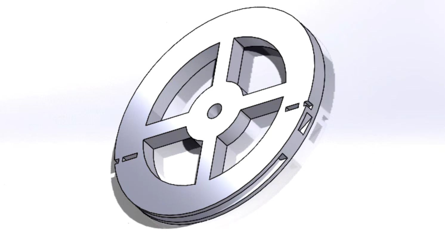
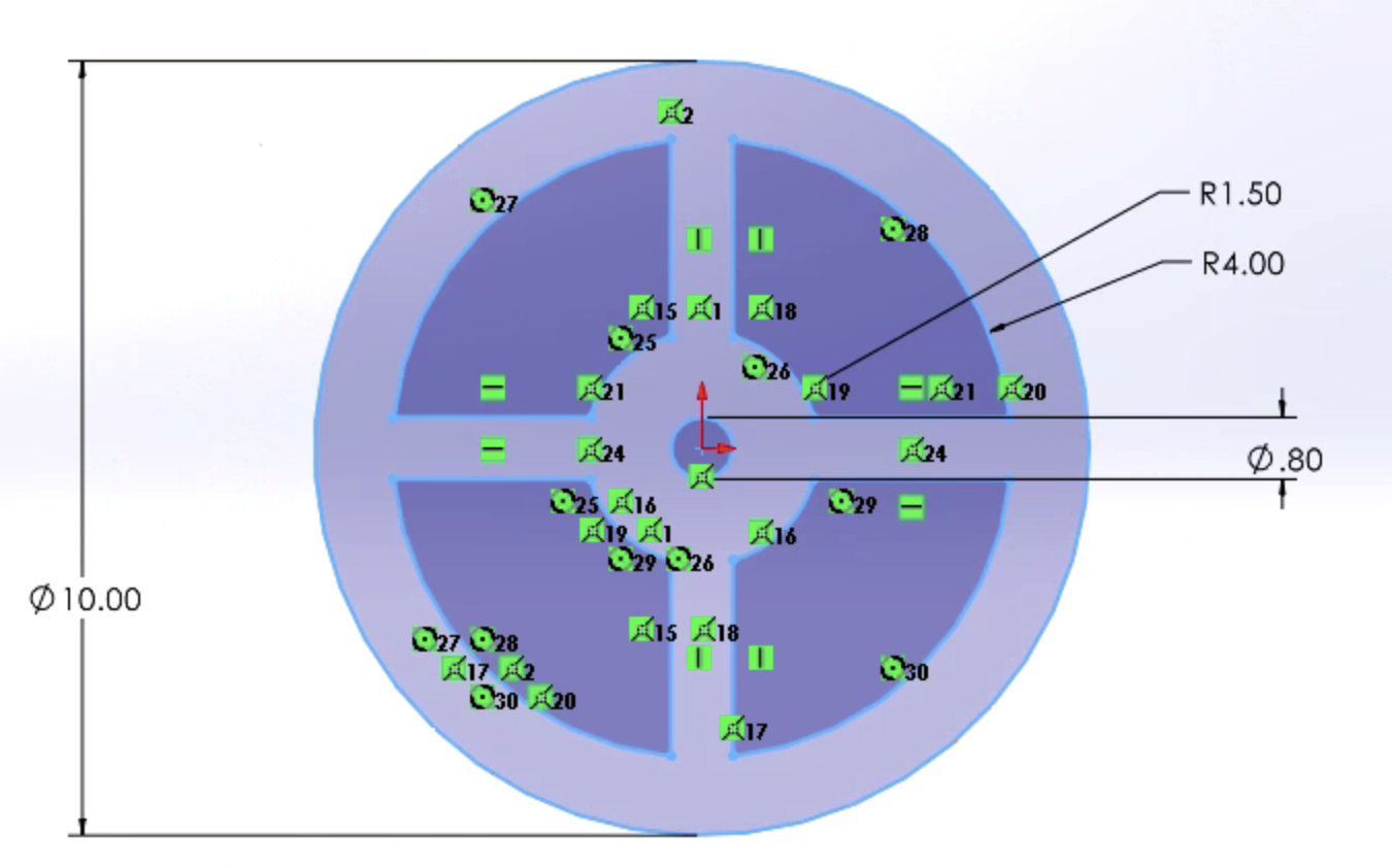
1. We use CAD to draw the wheel that has the correct dimensions to fit into our haptic device. You may download it from the File section. It simulates a real-world wheel when driving. Note that the size of the wheel should fit into the 3D printer to use.
 2D view of the CAD wheel


 3D view of the steering wheel
2. Then 3D print it using fine materials and high resolution in the lab. You may use polishing techniques like heating, filing, and washing to strengthen the material and improve the texture.
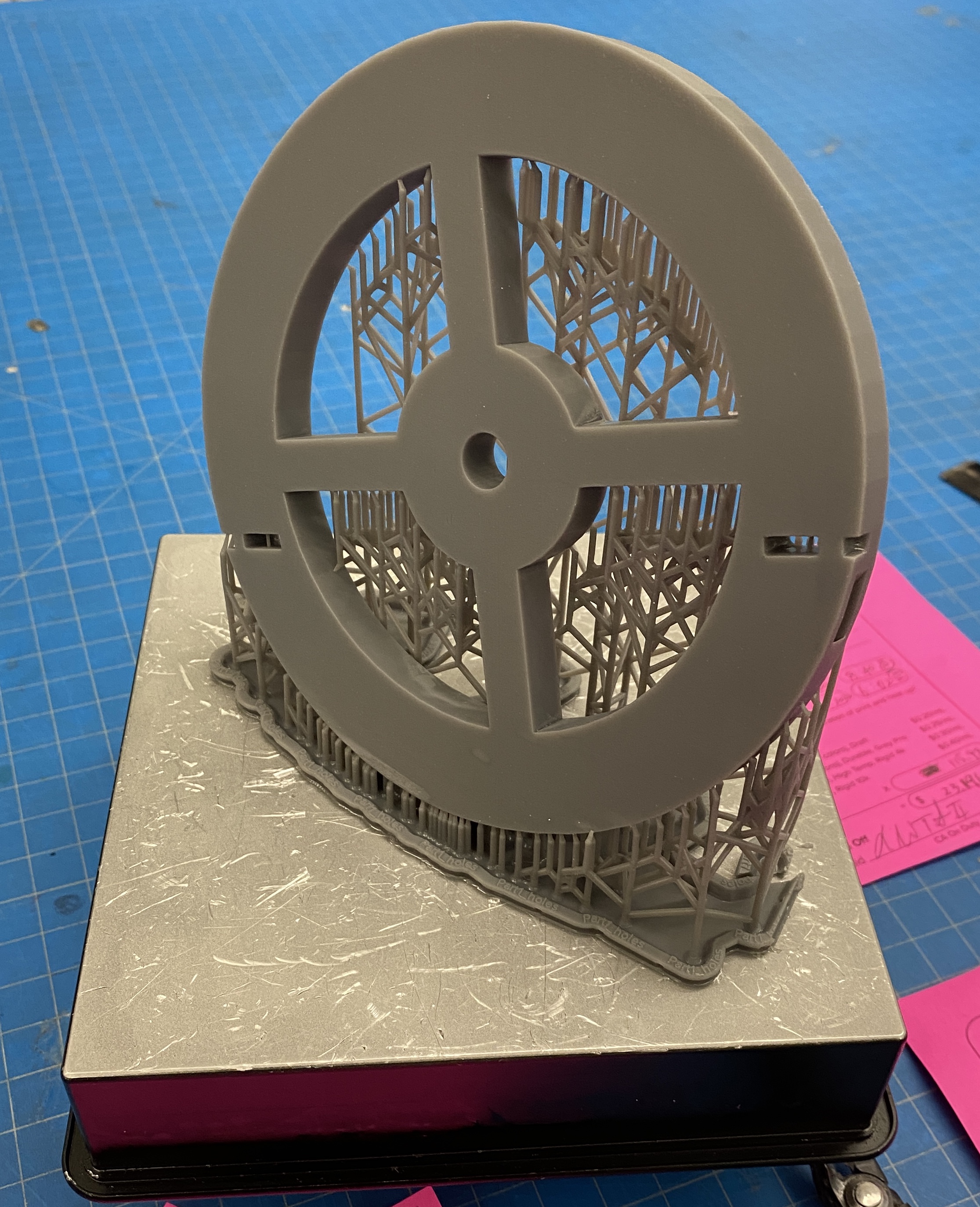
3D printed wheel
Components Assembly
As shown in the design figure, the force transmission mechanism is driven by the cable. The torque is provided by the motor.
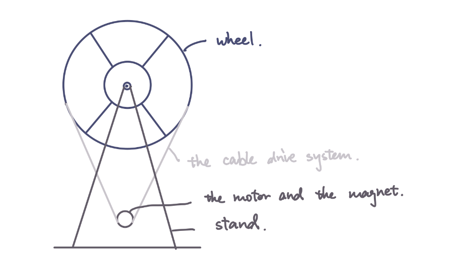
Force transmission mechanism
We reuse the hapkit provided in the ME 327 lab, using the hapkit base, motor, sensors, and hapkit board. The steps to assemble them are given in detail as follows. Steps are referenced to ME 327 material.
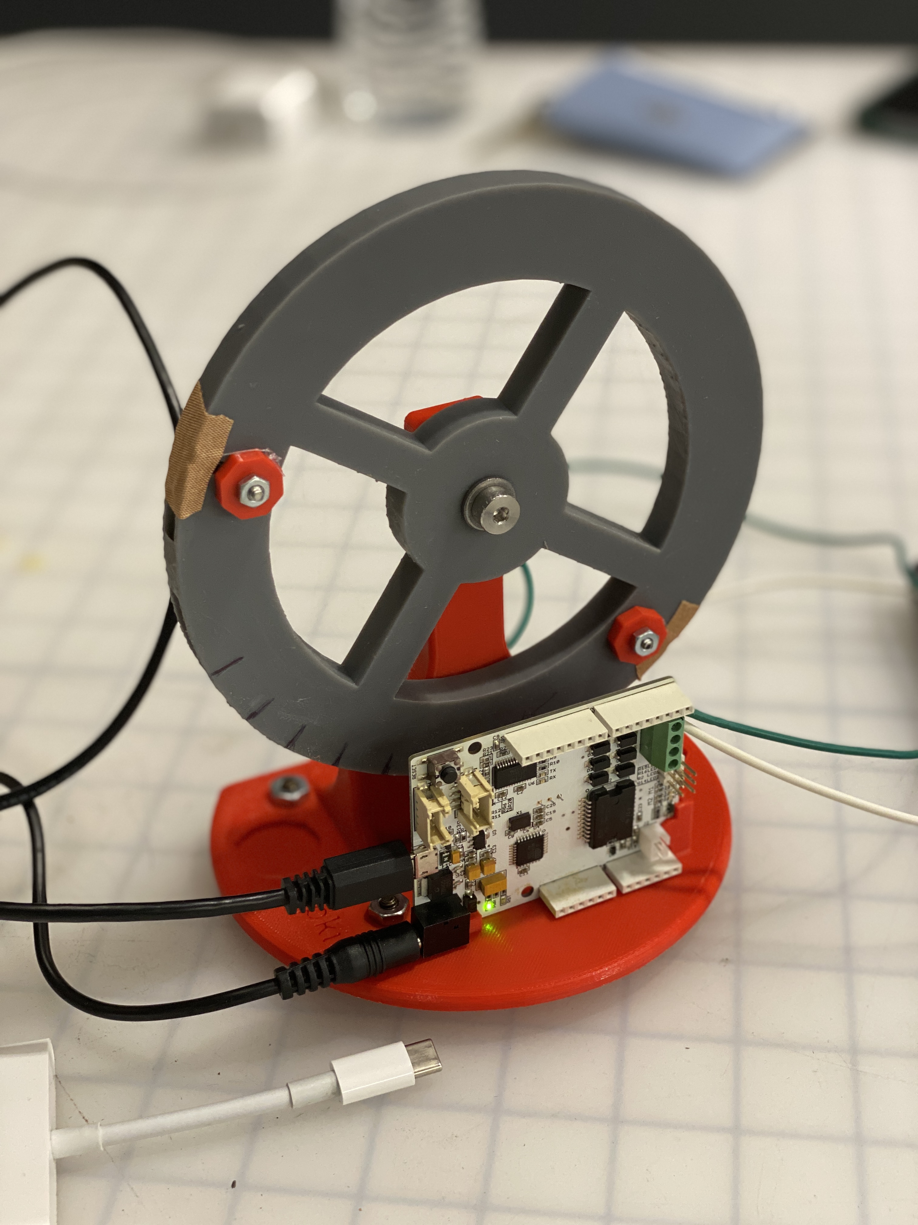
Final Assembly
Attach the motor to the base
a. Attach the motor to the 3D printed base by pushing the shaft through the hole.
b. Tighten the motor with screws and washes.
Assemble the drive wheel
a. Insert a 3D-printed drive wheel into a tube
b. Insert the magnet to the magnet holder at the end of the 3D-printed drive wheel
c. Apply superglue on the motor shaft
d. Slip the drive wheel over the motor shaft
Attach the wheel to the base
a. Place a shoulder screw into the hole of the 3D-printed steering wheel, and screw the shoulder screw into the hole on the 3D-printed base until a secure attachment is made.
b. After assembly, the steering wheel should rotate freely.
Assemble the cable/capstan drive system
a. Form a ring with the cable and compression sleeve.
b. Crimp the compression sleeve so that the cable does not move
c. Place a screw into the hole on the 3D-printed steering and through the ring of the cable.
d. Tighten it with a 3D-printed washer
e. Pull the cable along the steering wheel and form a cable driven system
f. Attach the end of the cable to the steering wheel by repeating (a) to (d).
The final assembled haptic device are displayed as in figure Final Assembly.
Software Design and Implementation
We build the GUI using the Processing software. The underlying data structure in Arduino is a 2D array, where the obstacle spaces are filled with ones and free spaces are filled as zeros, which increases efficiency when we determine if the car is hitting the wall.
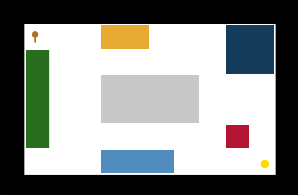
Arriving at the destination with a sign indicating success.
Due to the limitation of the Arduino board memory and computational speed, we discretize the world into smaller segments, in other words, in low resolution. The final visualization of the map in the Processing interface is displayed below. You can download the processing file in the File section.
System Dynamics & Control.
We output three values for Processing to draw on visualization: car location x, y, and its orientation theta. Therefore, in Arduino code, we need to calculate the three values for the processing code to catch.
After calibration, in our case is steer_angle = (updatedPos-900) * (-0.01324) - 1.857, we are able to get the angle the steering wheel stays. Therefore, the new orientation is calculated as follows, where the steer_ratio is tuned for a reasonable size for stable visualization. If a collision happens, world_x and world_y are not updated while the orientation can be changed by the steering.
world_theta = steer_angle / 180 * PI * steer_ratio + world_theta;
Then we can update the new position represented by world_x, world_y, where carSpeed is tuned for a reasonable value for stable visualization.
world_x = world_x + carSpeed * cos(world_theta);
world_y = world_y + carSpeed * sin(world_theta);
The force and torque output is tuned to simulate the real-world haptic feeling with a constant coefficient.
Results

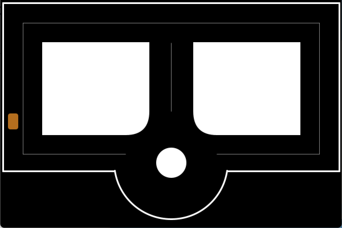
Autonomous wheel steering when bumping into obstacles.
We demonstrated our haptic steering wheel to students in ME 327, as well as the open house guests. We were given high remarks on the project idea, design of the visualization, reality of the hapkit input and output, and robustness of the system. "The topic is super cool and I cannot wait to try that out!" "The turning is accurate and I feel I can control pretty well now." "The controlling panel is giving me the forces that I felt like I am driving my Tesla!"
Reality
The reality of the force is enhanced by tuning the magnitude of the force coefficient. We would like to mimic the feel of being instructed when making the turns in the real world. During the demonstration, the instructive force for people to make turns are mild and realistic so that guests felt comfortable being guided during driving.
The manufacturing process also added great value to mimicking the realistic texture feeling of the steering wheel. We selected higher resolutions for 3D printing with more robust material and additional surfacing washing and heating after printing. In the assembly, we filed the surface of components to make sure they fit perfectly so there are no zigzags or noises when steering the wheel.
Stability
The stability of the system is improved through the iterative process that we fine-tuned the visualization with the underlying Arduino code data structures. We tested out different map layouts in collaboration with the hardware 3D printed driving wheel to see the robustness of the algorithm and beautify the code implementation to achieve higher computational efficiency in the limited memory of the Arduino board.
The implicit trajectories on the GUI visualization that we designed for guests to run are subject to several obstacles that can deliberately hit and experience the output from the haptic device. These would make our demonstration efficient and satisfactory, improving the stability of the system.
Completeness of design:
The completeness of the design is based on
1) GUI implementation - supported by processing code. We are able to apply GUI design philosophy to add complexity and interesting visualization to improve user experience. We had a starting point at the left upper corner and the final destination at the lower right corner with a congratulation animation indicating the success of the demonstration.

Arriving at the destination with a sign indicating success.
2) Hardware manufacturing - the refined 3D printed wheel and assembly of the haptic components are crucial to the accuracy of the sensor input and thus the haptic output, which directly leads to the reality and stability of our system.
3) Code development on Arduino board for dynamics: The data structures are specifically designed for better computational efficiency, and the iterative testing helps us make sure that the software and hardware fit each other perfectly and add great value for a better user experience.
The overall completeness of the design is tested among team members and proven during the open house demonstration.
Future Work
For future work, we can extend the project to achieve a higher level of complexity using more robust hardware.
1. Arduino board has small memory and speed for computation, limiting the size and resolution of our driving map. Therefore, we could extend the complexity of the driving environment with increased resolutions and with more shapes: curved roads, etc. We may use boards that are more robust and memory-sufficient like the Raspberry Pi.
2. With greater board capability, we may apply abundant autonomous driving algorithms like SLAM to make the simulation more applicable to real-world scenarios.
Files
Please check the attached for a complete demonstration video.
Attach:video20.mp4
You can download our files from the public repository on GitHub for 3D printing file, Arduino code and Processing code.
Github repository for the files [https://github.com/kexinweng/me327code.git/]
Arduino code [https://github.com/kexinweng/me327code/blob/main/Arduino/ME327_Final/ME327_Final.ino/]
Processing code [https://github.com/kexinweng/me327code/blob/main/ME327_Final/ME327_Final.pde/]
STL file for 3D printing [https://github.com/kexinweng/me327code/blob/final/Part1_holes.STL/]
Cost of materials: Attach:team20cost.pdf
References
[1] Tanaka, H., Ohnishi, K., Nishi, H., Kawai, T., Morikawa, Y., Ozawa, S., and Furukawa, T., �Implementation of bilateral control system based on acceleration control using FPGA for multi-DOF haptic endoscopic surgery robot,� IEEE Transactions on Industrial Electronics, Vol. 56, No. 3, 2008, pp. 618�627.
[2] Benloucif, M. A., Nguyen, A.-T., Sentouh, C., and Popieul, J.-C., �A new scheme for haptic shared lateral control in highway driving using trajectory lanning,� IFAC-PapersOnLine, Vol. 50, No. 1, 2017, pp. 13834�13840.
[3] Wan, Y., Cutlip, S., Bhardwaj, A., Ghasemi, A., Watts, L., Garber, B., Sarter, N., and Gillespie, B., �Haptic Shared Control: Improving Human-Automation Collaboration in Semiautonomous Driving,� , 05 2018.
Appendix: Project Checkpoints
Checkpoint 1
[What we have finished]
1. User Interface implemented using Processing Language
We built our user interface via Processing, a flexible software sketchbook. On the interface, we show a little town with different types of roads such as the straight lanes, roundabouts, and T-intersections, as well as a vehicle moving at a constant speed. The direction of the vehicle is controlled by the hapkit and shown on the user interface. The initial version of the design is a two-lane configuration. The vehicle is restricted to driving on the lanes, so we will prevent it from passing through the buildings or walkways visually. The finished visualization of the autonomous driving environment using Processing language is shown below.
2. A skeleton Arduino code template
The codes will be used for taking input from the haptic devices and giving control signals to the vehicle is finished. We take the template codes for homework as a reference.
3. Hardware manufacturing & Assembly
Most of our hardware can be reused from the previous projects, including the 3D-printed base, stand, cables, and screws. Additionally, we need to 3D-print a stirring wheel and attach it to the stand via the shoulder screw and the bearing. The stirring wheel can be rotated freely with a cable/ capstan drive system. We have finished the CAD preparation and slicing for the 3D printing part.
[What Remains to be done]
1. 3D printed parts assembly for the haptic device as the sketch below. Integrate the control Arduino codes with the Processing user interface.
2. Calibration and testing of the Arduino control codes with the haptic device control panel.
3. Validation of results and improve the quality of the demo. Preparation of presentation and report.
The progress is under a good control and meets our expectations as listed in the proposal. We are confident that we can deliver a more stable and realistic demo in the next stage and final presentation.
Checkpoint 2
[What we have finished]
1. User Interface implemented using Processing Language
After we built the initial version of the interface, we are able to connect the interface with the Arduino code for simulation using the codes we have developed. We also make some changes based on the testing - modifying the size of the car (turtle bot) to make the simulation more smooth. This part is subject to further adjustment and iterations.
2. Arduino code finished
The skeleton code (template) has been filled with our detailed design so that we are ready to test them on our hardware.
3. Hardware manufacturing & Assembly
We finished the 3D printing of the stirring wheel and assembled the haptic device that will be used in our project.

[What Remains to be done]
1. Testing of integration of hardware and software, and iterations for parameters for smooth demonstration.
2. Composition of the final report.
3. Rehearsal of class demonstration.
Our team works together regularly to meet the proposed plan. We are confident that we could deliver a refined work in the final demonstration date to the audience.