

Group 7
Enabling In-Bore CT-Teleoperated Needle Insertions with Haptic Feedback
Project team member(s): Paul Diederichs, Yulin Huang, Genggeng Zhou

Team members with
device at demo day
The goal of our project is to develop a one degree of freedom injection teleoperation device that enables in-bore CT needle insertions. We hope to design a haptic device that enables physicians to more quickly and accurately place needles required for the treatment of herniated disks. Note that this project is motivated by Paul's personal experience.
Introduction
Motivation: This project is motivated by Paul's personal experience. After Paul was diagnosed with a herniated disk two years ago, he received numerous CT guided cortisone injections to alleviate his pain. To ensure that the cortisone was injected directly into the spinal canal at the height of the herniated disk, the injection was performed with medical image guidance. The exact CT guided injection procedure he underwent was as follows:
- The physician felt up his spine to approximately localise the herniated disk via haptic feedback. This step was performed without any feedback from medical images.
- Next, the physician inserted three needles around the localised herniated disk. When initially inserting the needles, the physician did not push the needles all the way into the spinal canal.
- Once the needles were placed at their approximate locations, the physician moved Paul into the CT device and medical images were taken. These images were used to guide the physician as he further inserted the needles into Paul�s spinal canal.
- Next, Paul was pulled in and out of the CT scan as the needles were iteratively positioned. He was pulled out of the CT bore a total of 4 times, until the needles were located at the desired position.
- Finally, once the needles were at their correct location, the needles were used to inject cortisone directly into the spinal canal.
Note that this outlined procedure is cumbersome and prone to error caused by needle bending. Ideally, the physician would have the ability to perform the injection remotely by manipulating the needle via teleoperation while the patient is imaged. In this case, the patient would not have to be pulled in and out of the medical imaging device as the needle is inserted a portion of the way.
Background
There exists a rich amount of literature on the teleoperation of medical needle insertion devices. Prior works include an MRI-guided liver biopsy device, an experimental evaluation of the importance of haptic feedback in detecting tissue transitions, and a leader-follower system for prostate examination. Thus, our project is an extension of existing work. In particular, we apply previously gained insights to develop a device that enables physicians to more quickly and accurately place needles required for the treatment of herniated disks.
Our haptic device was primarily inspired by Frishman et al.'s work [1] on a compatible in-bore MRI-guided needle insertion device. Frishman et al. [1] present a device that enables physicians to perform rapid and accurate MRI-guided liver biopsies via teleoperation. In particular, they design a teleoperated needle insertion device that allows physicians to manipulate a biopsy needle remotely while the patient is imaged. This way, the physician can perform the biopsy with constant visual feedback. In addition to visual feedback, the device provides continuous haptic feedback. The device propagates all interaction forces between the needle and the penetrating tissue to the physician. This haptic feedback aids the physician in differentiating between contact and penetration of the liver membrane. Additionally, Fisherman et al.'s work [1] emphasizes the importance of system transparency when designing a medical needle insertion device. Their design ensures unity force tracking at low frequencies corresponding to typical manipulation speeds. They achieve unity force tracking by minimizing the system's internal friction via hydraulic transmission and pneumatic actuation.
Seifabadi et al. [2] developed a leader-follower robotic system for teleoperated transperineal prostate biopsies. Their device consists of a pneumatically actuated leader and follower robots. A position controller ensures that the follower robot accurately tracks the position of the leader. However, the designed system lacks force and haptic feedback. Consequently, the application of the introduced device is limited when visual feedback does not suffice for the accurate placement of the needle.
The importance of haptic feedback when performing needle insertions with limited vision is highlighted in Gerovich et al.'s work [3]. They evaluated the ability of subjects to identify punctures of different tissues when provided with varying haptic and visual feedback. They determined that the importance of haptic feedback increases when the visual feedback degrades. Overall the authors stress the importance of providing both force and visual feedback. A combination of both visual and haptic feedback achieved the best results in identifying tissue transitions and minimized overshoots.
Methods
Our design consists of a leader and follower, whereby the leader functions as the input and the follower as the output device. In particular, the user operates the leader device to control the follower device to which a needle is attached.

While the leader device is an original hapkit, the follower device is a heavily modified hapkit. The design of the follower system accommodates the following design requirements:
- The follower device must transform angular into linear motion because the needle must penetrate the tissue along a line.
- The needle's range of motion must be at least 15 centimeters so that it can be placed correctly
Additionally, the follower design includes a clutch and motion descaling. The clutch disengages the leader from the follower so that the operator can reset the position of the leader handle. This reset emulates a needle insertion via multiple strokes.
Hardware Design and Implementation
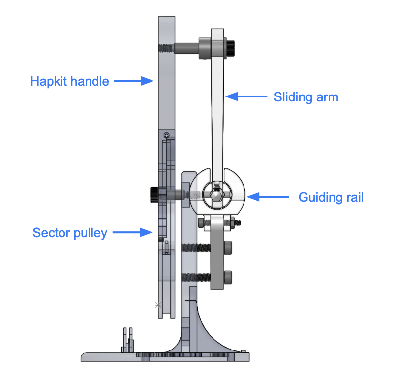
The figure below depicts the overall design of our follower system.

Slider and Guiding Rail
For the follower device, we designed a slider and guiding-rail system to convert the circular motion into linear motion. The guiding rail structure is mounted to the base of the hapkit via two support arms. A slider moves horizontally within this guiding rail. The mock needle (a pencil) is fixed to the slider, thus enabling the needle to move horizontally. The slider connects to the hapkit's motorized handle via a linkage. This linkage is attached to the slider with a plastic bearing to reduce rotary friction, and is connected to handle using a shoulder screw, sleeve bearing and shaft collar. Note that this linkage is responsible for transforming the angular motion of the hapkit's handle into linear motion.
The figure below details the design of the guiding rail and the slider.


Hapkit Handle and Sector
On the follower side, we also redesigned the hapkit handle to extend its range of motion. We increased both the handle's length and the sector radius.

Clutch and Downscaling Buttons
We have two separate physical buttons (momentary push buttons purchased from amazon). One button engages the digital clutch, and the other activates motion descaling. Note that the buttons easily connect to the hapkit board via push pins. Additionally, we designed an encasing for the buttons. The encasing has an outer diameter of 2.5 cm, and a wall thickness of 0.5 mm. (The right image above shows the two push buttons in their encasing.)
Software Design and Implementation
Clutch Implementation
The idea of the clutch is to disengage the leader from the follower. When the clutch is engaged, the follower remains stationary. The clutch momentarily interrupts the position tracking between the leader and follower. An activation enables the operator to move the leader's handle without altering the follower's position. This disengagement allows the needle to be moved across its complete workspace. Since the follower's range of motion exceeds that of the leader, the full range of motion on the follower's side cannot be realized without a clutch. We realize this clutch digitally. The pseudo-code below mirrors our implementation.

Motion Downscaling Implementation
We introduce motion downscaling for more refined needle control. When motion descaling is engaged, the needle moves half of the distance covered by the leader. In other words, if the leader moves a distance of 2x, the follower only moves a distance of x. This descaling helps reduce the needle's overshoot, as it initially pierces through the tissue. The user activates the motion descaling by pushing a button. We achieve motion descaling via the following algorithm.

Visual Feedback
We provide continuous visual feedback on the follower's position. The provided visual feedback crudely emulates the CT images a physician sees when conducting the procedure. A simple python script generates the visualization. The python script builds on the provided teleoperation script. At each time step, it extracts the position of both the leader and follower from ports at a baud rate of 115200. From the extracted positions a rendering is generated. The rendering algorithm runs at a high frame rate to not delay the serial communication between the leader and follower. See code here: Attach:hapkit_teleop_new.zip

The skin is rendered to deform upon contact and pierce only after exceeding a certain penetration depth. The bone is modeled as a hard surface through which the needle cannot penetrate. In the rendering, the needle's position never exceeds that of the bone.
System Analysis and Control
System Dynamics

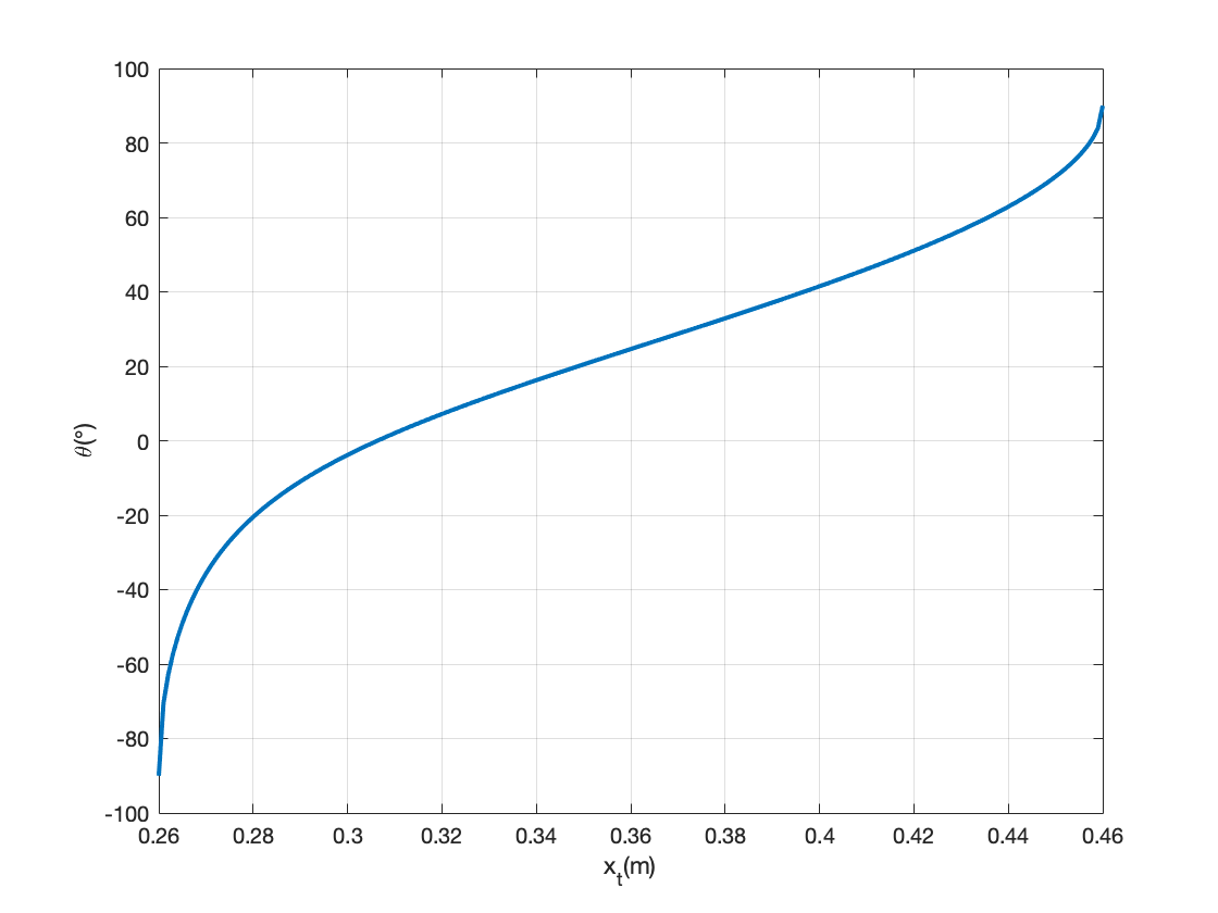
The relationship between the needle position and the sector pulley angle is nonlinear, but the derivation is very straight forward, as shown in the figure above. Plotting the value of x't' for a range of θ gives us the plot below.


Controller Design
We use a bilateral controller to track both the position and forces. The forces acting on the needle are derived from the needle's and teleoperated handle's position and velocity. It assumes that a virtual spring and damper accurately capture the acting forces, i.e. the force feedback is a PD controller based on position. Our bilateral teleoperation controller achieves a low tracking error and high system transparency. Therefore, any forces or position changes conducted by the leader are very noticeable by the follower and vice versa. Furthermore, the resulting bilateral teleoperation controller is stable, i.e. it does not exhibit undesired oscillations.
A block diagram of our control architecture is depicted below.

The bode of the resulting theoretical transfer function is depicted below:

Note that near unity position tracking is observed at realistic manipulation speeds.
Alternative Design
An alternative design we tested included a crude force sensor, namely a thin film sensor. The thin film sensor was placed between the mock needle and slider to directly sense the acting forces on the mock needle. Unfortunately this method did not work due to noisy force readings and frequent reset errors. We experienced a lot of difficulties calibrating the force sensor. Furthermore, the force sensor's measurements exhibited bias after compressions.

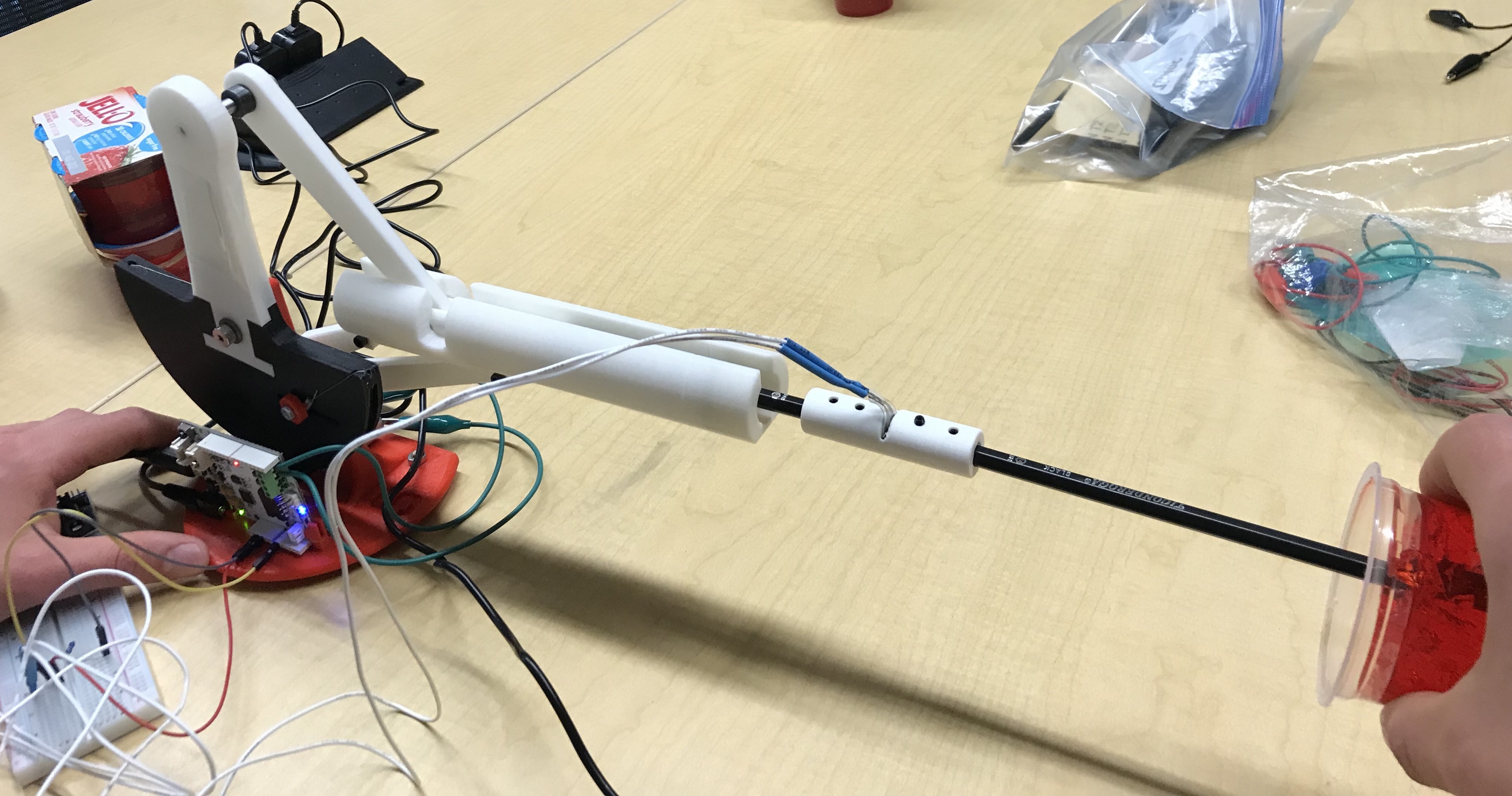
Results
At our open house demonstration, we had users test our device. In particular, users performed a simulated CT-guided needle insertion. They relied on visual and haptic feedback as they teleoperated the follower needle. Ultimately, they inserted the "needle" (a pencil) into "human tissue" (jello, whose spring constant is similar to human tissue). We provided visual feedback to the users by rendering the needle's position relative to the artificial human tissue. Additionally, the forces acting on the needle as it penetrated the jello were relayed to the user via a bilateral controller.

Overall, the users' reactions to the device were very positive. The users were impressed by the realism of the haptic feedback. Many users were astonished at how real the whole procedure felt. All users noted that they felt a reactive force, as they first penetrated the artificial human tissue. Unfortunately, some users described the system as unresponsive at times. These users experienced significant overshooting when inserting the mock needle. The system's internal friction caused the needle to overshoot at times.
Future Work
Currently, our haptic needle insertion device is a low fidelity prototype that conveys the potential of using a haptic teleoperation device to perform CT-guided cortisone injections. Yet, our device is not ready to replace traditional injection methods. There are significant improvements required before moving toward clinical studies with orthopedic surgeons and artificial tissue.
First and foremost, a significant reduction in the system's internal friction is required to ensure more accurate position and force tracking. The high resistive force between the plastic guiding rail and the slider results in a jerky and unsmooth system response. Frequently, the electric motor on the follower device cannot overcome the internal friction. In these cases, the follower fails to track the leader's position, and thus, the system feels unresponsive to the user. Furthermore, the internal friction contributes to follower overshooting. A potential solution to reducing the internal friction is to replace the guiding rail and slider with a hydraulic piston.
Another improvement would be to use a compression and tension load cell to measure the force when pulling and pushing the needle and relay that measurement back to the user instead of using thin film force sensors or bilateral force feedback. The threaded structure on the load cell provides means to measure both compression and tension, and as a result, can create a more realistic haptic feedback.
Additionally, accurate force tracking is crucial in medical settings. Ideally, the system exhibits unity tracking between the input force on the needle and the output force relayed back to the operator. An evaluation of the system's force tracking performance requires system identification experiments. These experiments would test the current bilateral force controller. A system identification experiment includes the excitation of the needle at a given frequency and amplitude. Two force sensors, one mounted to the leader and one to the follower, then measure the force exerted on the needle and the force relayed back to the leader. This experimental setup allows for an accurate evaluation of the system's force tracking performance.
Another step is to extend the device's design to include additional degrees of freedom such that an orthopedic surgeon can adjust the needle orientation during insertion. While accurate force tracking and high fidelity haptic feedback are less important when adjusting the needle orientation, low friction and back-drivability remain crucial as they enable the system to adjust passively to the patient's motions.
Acknowledgments
We like to express our gratitude to Professor Allison Okamura and the teaching team for their help and feedback throughout our project.
Files
See the attached Solidworks design and 3D printing files, Attach:ME327_design.zip. Note that the total costs associated with 3D printing the additional parts is approximately 25 dollars.
Part list: Attach:Parts_list.xlsx. Code: Attach:needle_teleop.zip
References
[1] S. Frishman, A. Kight, I. Pirozzi, M. C. Coffey, B. L. Daniel, and M. R. Cutkosky, �Enabling in-bore mri-guided biopsies with force feedback,� IEEE Transactions on Haptics, vol. 13, pp. 159�166, 1 2020.
[2] R.Seifabadi, S.E.Song, A.Krieger, N.B.Cho, J.Tokuda,G.Fichtinger, and I. Iordachita, �Robotic system for mri-guided prostate biopsy: Fea- sibility of teleoperated needle insertion and ex vivo phantom study,� International Journal of Computer Assisted Radiology and Surgery, vol. 7, pp. 181�190, 2012.
[3] O. Gerovich, P. Marayong, and A. M. Okamura, �The effect of visual and haptic feedback on computer-assisted needle insertion,� Computer Aided Surgery, vol. 9, no. 6, pp. 243�249, 2004.
Appendix: Project Checkpoints
Checkpoint 1
Our primary goal for the first checkpoint consisted of designing and manufacturing the mechanical components for our haptic needle insertion device. In particular, we set out to redesign the Hapkit to enable the conversion of angular to linear motion. Furthermore, we hoped to explore design solutions that increase the range of motion of the Hapkit�s handle.
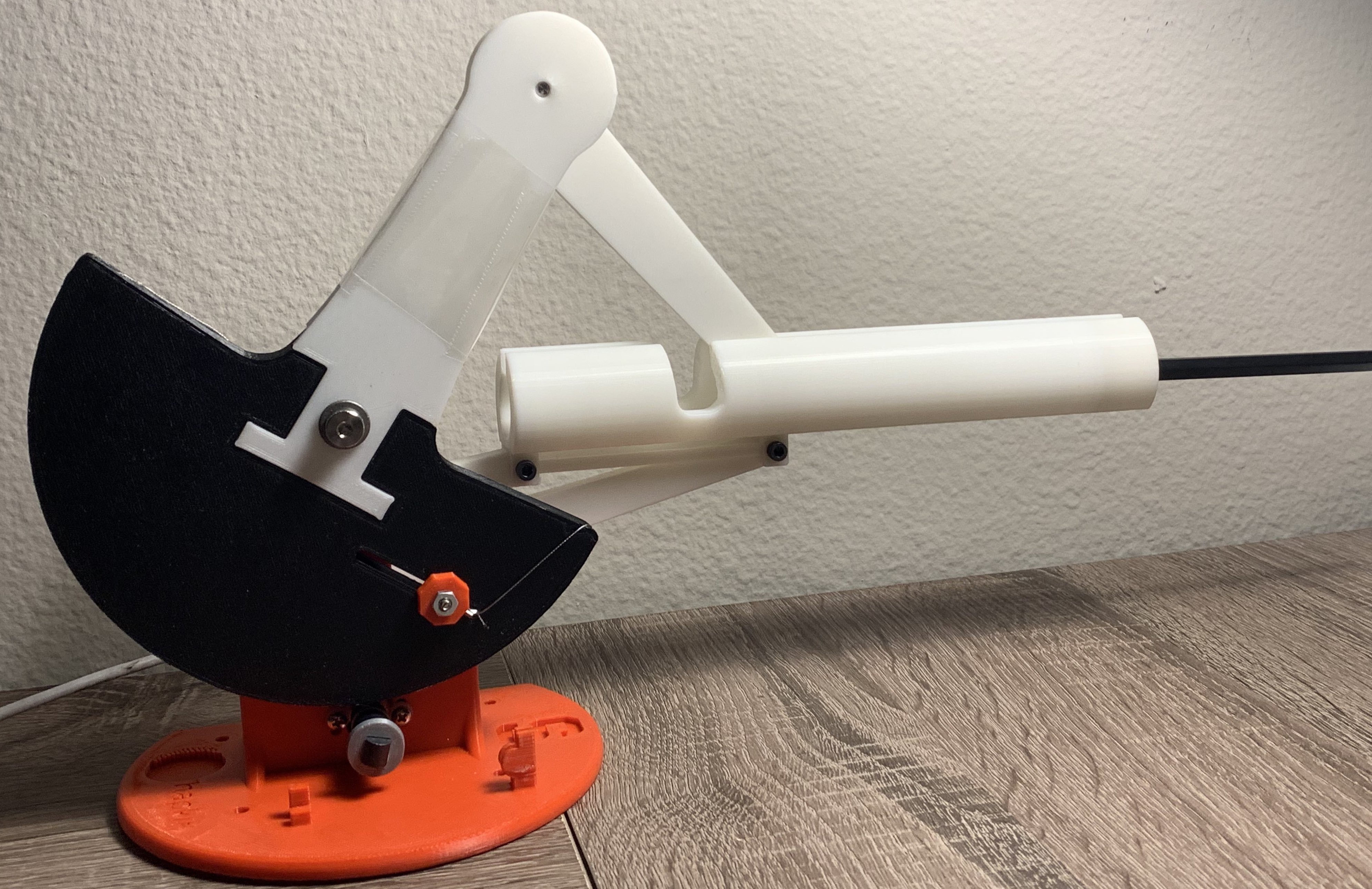
We have completed the mechanical design process: we realized our design sketches of the needle guide, the motion conversion system, and the new handle in Solidworks. The figure below depicts our final design and the animation shows the conversion of the angular motion to linear motion.

Next, we exported our designed parts to STL files and sent them off to be 3D printed. We then assembled the manufactured parts into our first version of the needle insertion device (see images below). Unfortunately, the guide for the needle needs reworking, as there is too much internal friction between the guide and railing. This friction hinders the needle guide from moving smoothly in the mount. Consequently, we have reduced the diameter of the needle guide.

In addition to our first checkpoint objectives, we have derived a mapping between the needle�s extension and the angle of the Hapkit�s handle. In other words, we determined the kinematics describing our one degree of freedom mechanical system. The plot below depicts the derived relationship between the handle�s angular position and the needle�s horizontal position. Note that the system�s kinematics are completely captured via the angle of Hapkit�s handle, which is measured via the magnetoresistive sensor.

Finally, we prototyped the virtual clutch. The virtual clutch is a software enabled clutch that allows for needle insertion via multiple strokes.
Checkpoint 2
Our goals for the second checkpoint consisted of implementing the required force tracking algorithms, defining the systems transfer function, and finally testing the whole system. In particular, we set out to have a fully functioning and tested haptic needle insertion device by the end of checkpoint two.
We tested two different force tracking designs. The first design consisted of a reimplementation of the bilateral teleoperation force controller. The forces acting on the needle are derived from the needle's and teleoperated handle's position and velocity. It assumes that a virtual spring and damper accurately capture the acting forces. Our bilateral teleoperation controller achieves a low tracking error and high system transparency. Therefore, any forces or position changes conducted by the leader are very noticeable by the follower and vice versa. Furthermore, the resulting bilateral teleoperation controller is stable, i.e. it does not exhibit undesired oscillations.
The second design we tested included a crude force sensor. Instead of modulating the acting forces via a spring and damper system, we tried sensing the acting forces via a force sensor. This bilateral force control design consisted of relaying filtered force sensor measurements to the teleoperator. While this bilateral controller is simpler, its performance is poorer than the bilateral controller relying on both position and velocity. Its poor performance is due to noisy force readings and frequent reset errors. We experienced a lot of difficulties calibrating the force sensor. Furthermore, the force sensor's measurements exhibited bias after compressions.
Since the bilateral force controller based on position and velocity outperformed the controller leveraging a force sensor, the final controller is a fine-tuned position and velocity force controller. A block diagram of our control architecture is depicted below.
The bode of the resulting transfer function is depicted below:
Note that near unity position tracking is observed at realistic manipulation speeds.
Next, we integrated the clutch within the control architecture. The clutch disengages the leader from the follower so that the operator can reset the position of the handle. This reset emulates a needle insertion via multiple strokes.

During this checkpoint we encountered internal friction problems. In our initial system tests, we experienced difficulties differentiating between the system's internal friction and the relayed haptic feedback. The system's internal friction was too large due to the sliding friction between the guide and the rail. Consequently, the system's transparency was low. We overcame this problem by sanding the surfaces. Additionally, we applied lubricant.