

Heravi Nowak Choi
Team 9: Hojung Choi, Jerome Nowak, Negin Heravi
Haptic Teleoperated Finger with Texture Rendering
Project team member(s): Negin Heravi, Jerome Nowak, Hojung Choi
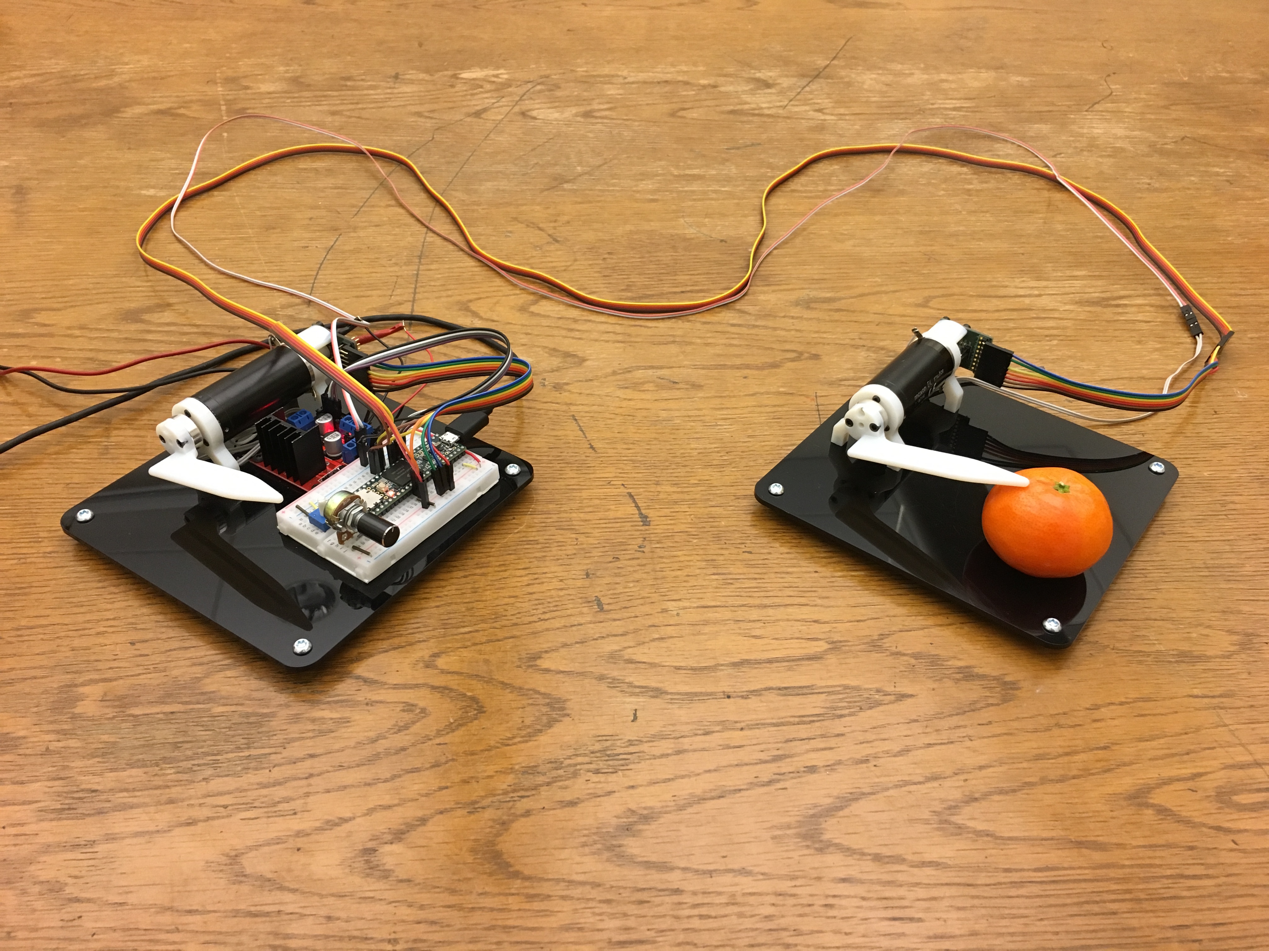
In this project, we designed a teleoperated master-slave pair of one degree of freedom fingers, wherein the master side rendered the deformability and texture of an object placed on the slave side. A position sensor placed on the follower side enabled us to render the sensation of interaction with objects of different stiffnesses using a basic proportional-derivative position-exchange bilateral teleoperator system. Furthermore, an accelerometer was attached to the slave side so as to detect vibrations, which were rendered through a dedicated haptuator attached to the master finger, such that it induced the feeling of interacting with a vertical textured surface in the 1D Pedal.
On this page... (hide)
Introduction
With the commercialization of several virtual and augmented reality devices over the past few decades, a diverse variety of applications in several areas such as e-commerce, gaming, educational, and medical has emerged. However, current virtual reality environments lack rich multi-modal sensory response such as auditory, haptics, and olfactory signals that humans receive during real life manipulation tasks. This lack of sensory information reduces the realism of these environments. Human brains are conditioned to expect the sense of weight, hardness, deformability, and slipperiness when interacting with an object, an experience that does not exist on commercially available augmented or virtual rendering devices. Furthermore, different textures induce different vibratory feedback on human's fingertips as they move their hand over a surface. Towards this end, we created a haptic device that enables you to sense deformability and texture of objects through a teleoperated system.
Background
Several researchers have been working on rendering textures by varying the magnitude and direction of the force imposed on the user by a grounded haptic device or by attaching a voice coil high-bandwidth vibrotactile transducer (such as a haptuator) that is capable of inducing specific acceleration signals to an Omni pen [1,2,3]. In [1], Culbertson et al. examined the importance of including texture, tapping, and and friction in generating a more realistic interaction with the virtual environment. In [2] , Culbertson et al. modeled 100 different textures using a piecewise autoregressive model. In [3], Romano et al. a data driven approach has been employed to model micro-scale surface texture using acceleration data. Another approach towards generation of a virtual texture can be achieved by using a teleoperation system where the master haptic device renders the signal picked up on the slave side [4,5]. In [5], Kontarinis et al. surface texture information collected from tactile array sensors on the slave side was processed to generate tactile information on the master side by controlling an array of pins. Inspired by these previous work, we are interested in creating a teleoperation system that renders deformability of objects upon interaction as well as texture of a vertical plane. Based on statistics from user studies, similar approach from the aforementioned work has been used to assess the realism of our system.
Methods
Hardware design and implementation
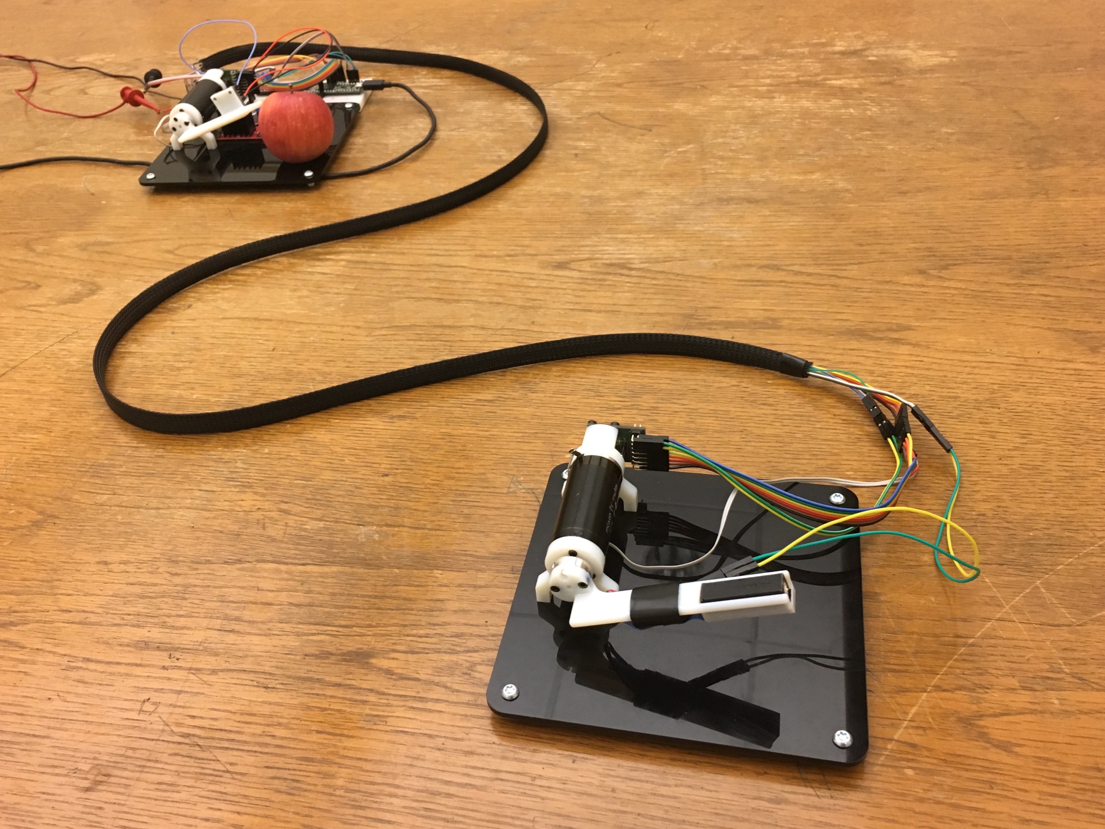
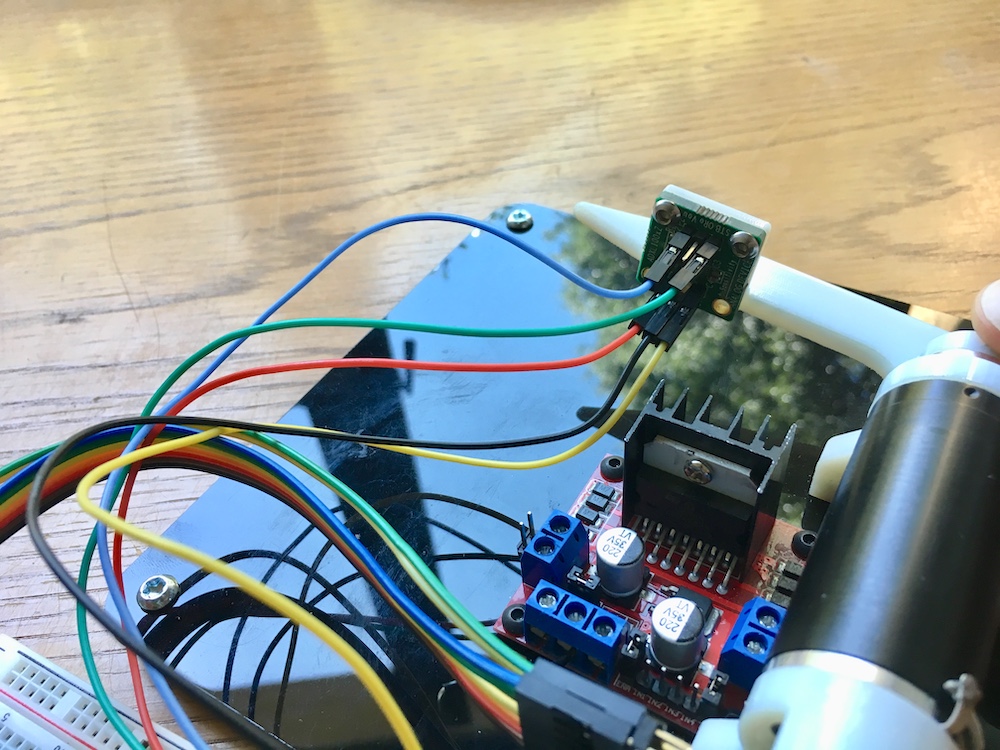
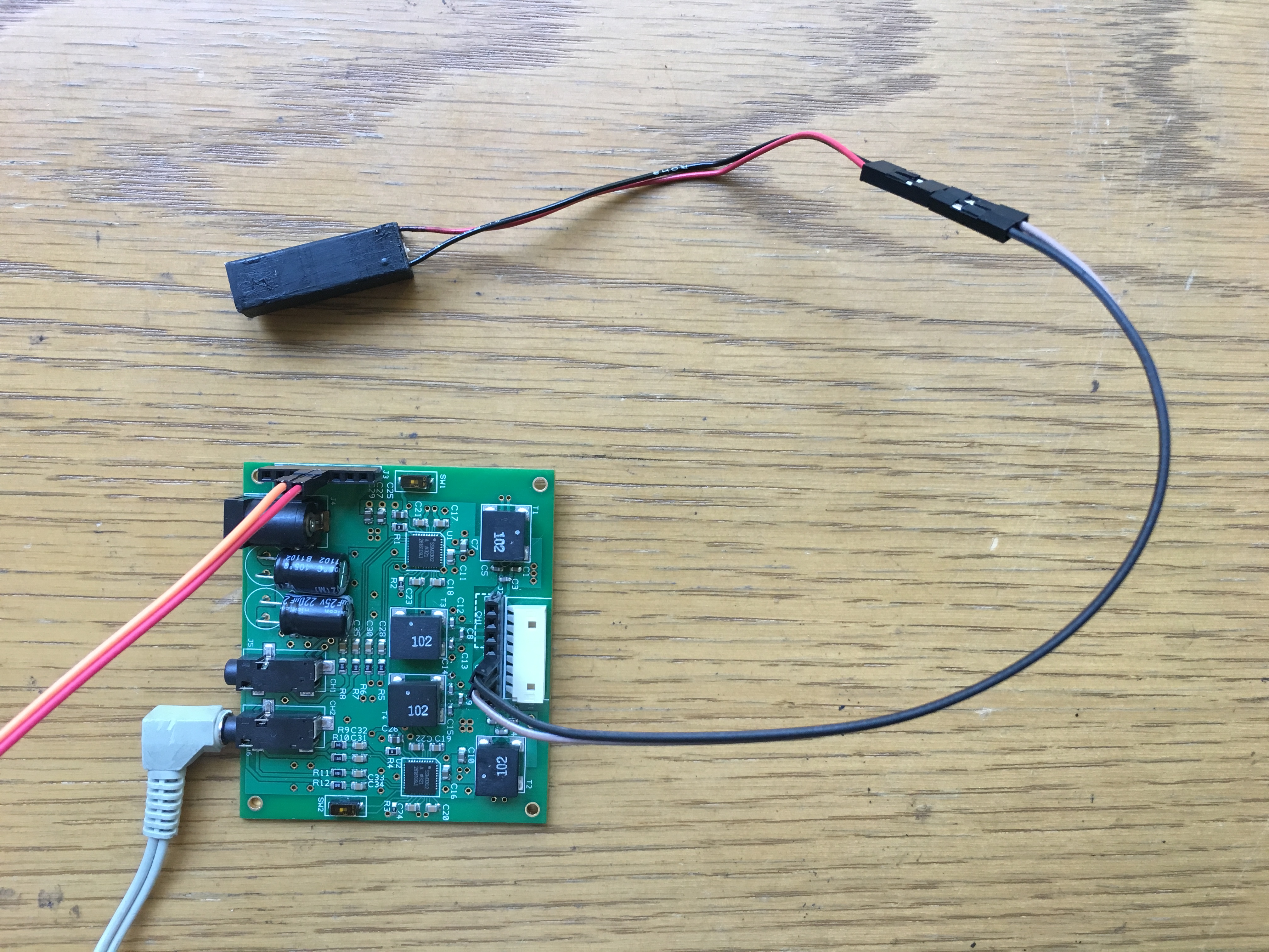
We designed and constructed a one degree of freedom finger pair, with each finger actuated by a high quality coreless Maxon DC motor (#118746) in direct drive. We chose direct drive so as to minimise friction and maximise fidelity while avoiding the extra mechanical complexity of a transmission system. The main drawback of this design was low stall torque. Each motor had a AS5047 14 bit digital Hall effect encoder mounted on its shaft, enabling frictionless position sensing. The chosen motor driver of this system was the MC33926 which allowed for high bandwidth (20kHz i.e. outside the audible spectrum) and current sensing for torque measurement. An analog one axis accelerometer (ADXL1002Z) was placed on the master finger for high frequency vibration sensing to render contact events and texture. A Haptuator was used to render the vibrations instead of feeding them through the motor coils as that allowed us to keep a fully analog feedback from the accelerometer to the Haptuator by utilizing an analog amplifier. This eliminated the need for an ADC and reduces lag between the master and slave. This choice however removed the possibility of digital signal conditioning, which could have been useful to compensate for the transfer functions of the accelerometer and the Haptuator, however this was deemed to be outside the scope of this study. Finally, we CADed the finger on the slave side such that it had a designated mount for the Haptuator.
System analysis and control
A teleoperation position feedback loop was implemented between the fingers. The controller for this loop was that of a bi-directional PID using position from the encoders as input and PWM on a motor driver as output. This enables the user to feel the compliance of an object placed on the slave side (within the maximum motor torque capabilities), much like the sensation of the wall rendered with the Hapkit, except we are feeling a real object. Using this setup, large scale texture features can be felt from the position feedback. One of the challenges faced in implementing this PID loop was that the Hall effect encoders delivered very noisy signals, and reading the absolute 14 bit position proved to be impractical, as the noise spectrum extended too low in frequency to warrant a digital low-pass filter. To overcome this, we simply made one 14-bit absolute measurement upon power-up, then used a different reading mode for 12 bit incremental position sensing, which was noiseless. The noise we originally encountered meant that the servo feedback loop was unstable, due to excessive peaks in the derivative term. Using the incremental 12 bit mode solved this as well.
As we were using a basic proportional-derivative position-exchange bilateral teleoperator system, the block diagram corresponding to our system was similar to that of the teleoperation homework (Diagram from ME327 HW Solutions). The only difference was that we were controlling the angle hence velocity in the diagrams refers to angular velocity.
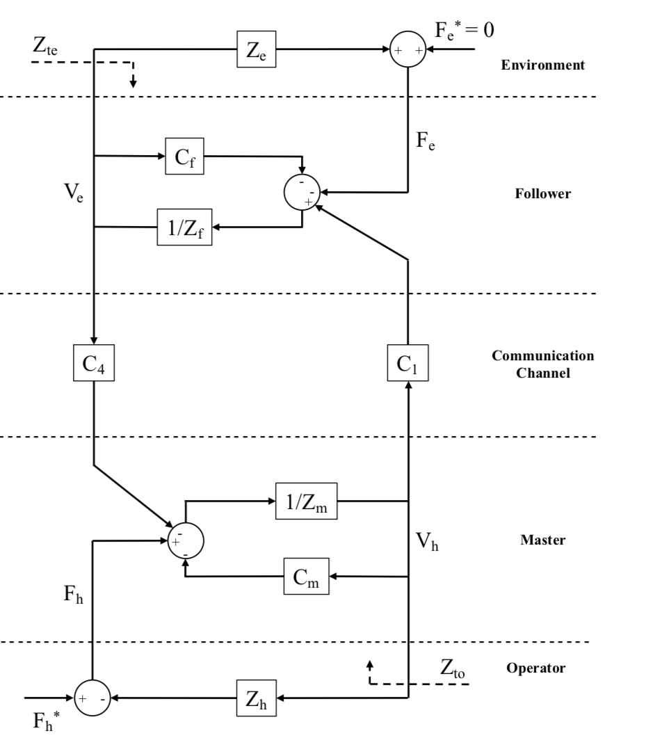
Where Zm = Imaster s +bmaster, Imaster = Imotor + Iattached finger
The Inertiamotor was found to be 10.5 g.cm2 from the manufacture's data sheet.
To gain an estimate of the the Iattached finger a beam model with a mass of around 12 grams was used. The formula for the I of a beam is : I = (1/3)ML2 where M = 12gram and L is 10 cm. As a result, Iattached finger was estimated to be 40 g.cm2
To simplify the modeling for now, damping values for the master and slave was neglected and assumed to be zero.
For the follower Zf = Ifollower s +bfollower, Ifollower = Imotor + Iattached finger + Idue to Haptuator
Imotor and Iattached finger are as above, and Idue to Haptuator can be modeled as a point mass placed at distance r from the rotor where m = 8.2 grams and r= 6.5 cm. As a result, Idue to Haptuator = m.r2 is found to be: 346.45 g.cm2
The Kp and Kd values for the controllers were tuned to insure stability of the system during different interactions.Given Kp and Kd the formula for Cs in the diagram is:
Cm = Master local position controller = (Kp_master /s) + (Kv_master)
Cf = Follower local position controller = (Kp_follower /s) + (Kv_follower)
C4 = Follower Coordinating Force Feed Forward Controller = -(Kp_master /s) - (Kv_master)
C1 = Master Coordinating Force Feed Forward Controller = (Kp_follower /s) + (Kv_follower)
Demonstration / application
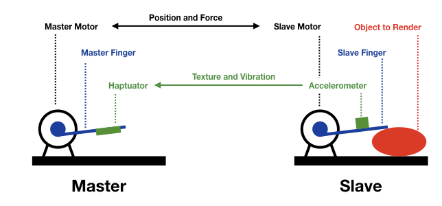
During the demo day for demonstration of the project, the user was asked to close their eyes and interact with the master device. For this interaction, the user strapped their finger on top of the master device’s finger and pivot it around their proximal finger joint. A second person placed different objects on the follower’s side and asked the user to describe the characteristics and/or guess the object they are interacting with based on the haptic feedback they receive. The following diagram shows the procedure more clearly:
Results
Our team had a questionnaire at the open house in which we asked the users to rate the realism of the textures on a 1-10 scale with 1 being the least real and 10 most realistic. 9 of the visitors who tried our device filled our questionnaire, however, due to the high number of visitors interested in trying our device not all the people filling the questionnaires experienced/rated all the existing objects. The list of objects available in the questionnaire were: Foam (Soft), Foam (Stiffer), Rubber Doll,Wood, Sand paper 1, Sand paper 2, Sand paper 3, Sand paper 4. Rubber doll and Sand paper 3 were only rated by one person hence their results were left out of the plots below.
In addition to these objects, visitors tried probing a plastic protoboard (a.k.a. breadboard) which is made of a smooth material but has millimetre-scale ridges and holes. This was not part of the study, but test subjects reported this object's haptic rendition felt very realistic.
Other verbal feedback we got regarding our apparatus includes:
- Because of the finite stiffness of our master-slave servo link, sometimes the slave finger does not follow the maser when stroking an object, so the master moves without having texture rendered on the Haptuator, which mistakenly feels like compressing a stiff spring instead of stroking an object.
- For some textures (particularly the foam), recognising them with eyes closed requires having felt them through the haptic interface with eyes open, to be able to learn what sensation they are rendered with. This learning phase would ideally be eliminated for all objects that one could recognise through direct touch with their eyes closed.

Future Work
One way our system can improve is to produce a more realistic rendering of the geometry of the object. The user study results suggest that subjects were not very convinced by the shape generated by the system. Also, while the current version of the texture generation is convincing, it is possible to expand the mode of conveying information on texture other than vibration. Moreover, the experiment itself can be further enriched by diversifying the properties of the object surface texture and stiffness.
Acknowledgments
We would like to express our sincerest gratitude to the Salisbury lab which provided plentiful resources in prototyping and building our system.
Files
N.B. We sent an email to the TAs and instructors with the files for our project.
References
(1) H. Culbertson and K. J. Kuchenbecker, "Importance of Matching Physical Friction, Hardness, and Texture in Creating Realistic Haptic Virtual Surfaces," in IEEE Transactions on Haptics, vol. 10, no. 1, pp. 63-74, 1 Jan.-March 2017. doi: 10.1109/TOH.2016.2598751
(2) H. Culbertson, J. J. López Delgado and K. J. Kuchenbecker, "One hundred data-driven haptic texture models and open-source methods for rendering on 3D objects," 2014 IEEE Haptics Symposium (HAPTICS), Houston, TX, 2014, pp. 319-325.
(3) J. M. Romano and K. J. Kuchenbecker, "Creating Realistic Virtual Textures from Contact Acceleration Data," in IEEE Transactions on Haptics, vol. 5, no. 2, pp. 109-119, April-June 2012.
(4) Dimitrios A. Kontarinis and Robert D. Howe. 1995. Tactile display of vibratory information in teleoperation and virtual environments. Presence: Teleoper. Virtual Environ. 4, 4 (January 1995), 387-402.
(5) D. A. Kontarinis, J. S. Son, W. Peine and R. D. Howe, "A tactile shape sensing and display system for teleoperated manipulation," Proceedings of 1995 IEEE International Conference on Robotics and Automation, Nagoya, Japan, 1995, pp. 641-646 vol.1.
Appendix: Project Checkpoints
Checkpoint 1 - Friday March 24
Checkpoint goals - Create a working prototype
- A hardware setup that is close to the final product the team in envisioning.
- Software should generate responses that resembles the experience the team is intending to provide.
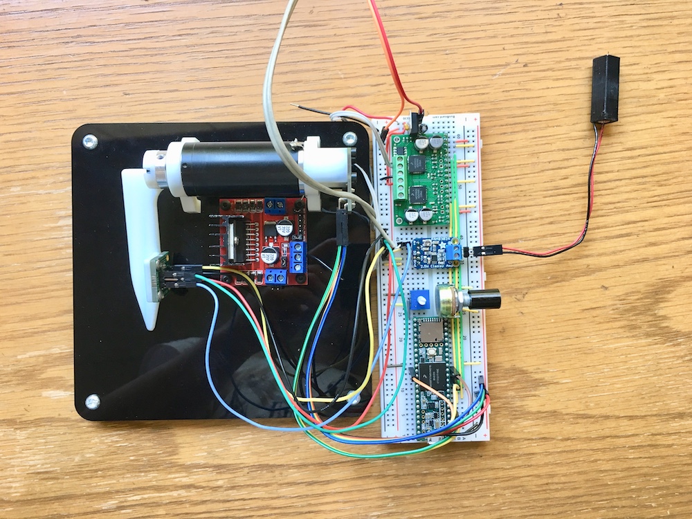
Goal 1 - We designed and constructed a one degree of freedom finger pair, with each finger actuated by a high quality coreless Maxon DC motor (#118746) in direct drive. We chose direct drive so as to minimise friction and maximise fidelity while avoiding the extra mechanical complexity of a transmission system. The main drawback is low stall torque. Each motor has a AS5047 14 bit digital Hall effect encoder mounted on its shaft, enabling frictionless position sensing.
Goal 2 - We have implemented a teleoperation position feedback loop between the fingers. The controller is a bi-directional PID using position from the encoders as input and PWM on a motor driver as output. This enables the user to feel the compliance of an object placed on the slave side (within the maximum motor torque capabilities), much like the sensation of the wall rendered with the Hapkit, except we are feeling a real object. Large scale texture features can be felt from the position feedback. We are currently implementing vibration sensing with an accelerometer.
Challenges - The Hall effect encoders deliver very noisy signals, and reading the absolute 14 bit position proved to be impractical, as the noise spectrum extends too low in frequency to warrant a digital low-pass filter. To overcome this, we simply make one 14-bit absolute measurement upon power-up, then use a different reading mode for 12 bit incremental position sensing, which is noiseless. The noise we originally encountered meant that the servo feedback loop was unstable, due to excessive peaks in the derivative term. Using the incremental 12 bit mode solved this as well.
Change of plans - We are on good track to meet our goals. We are exploring whether to use a haptuator for texture rendering or simply feed accelerometer data into the master motor coils.
Bellow is a photo of our current prototype.
Checkpoint 2 - Friday March 31
Checkpoint goals - Get ready for demo day
- Create a final version of the hardware
- Perform study on the principles of the device: Dynamic modelling, Impedance analysis
- Fine tune the software so that the team is proud of the performance of the device
- Prepare for demo: Design the experience of the user, Come up with means to quantify the performance of the device
Goal 1 - Final version of the hardware: We have built a second version of our finger pair, with a better motor driver (the MC33926) allowing for higher bandwidth (20kHz i.e. outside the audible spectrum) and current sensing for torque measurement. We added an analog one axis accelerometer (ADXL1002Z) for high frequency vibration sensing to render contact events and texture. We decided to use a Haptuator to render the vibrations instead of feeding them through the motor coils, as that allowed us to keep a fully analog feedback from the accelerometer to the Haptuator by utilising an analog amplifier. This eliminates the need for an ADC and reduces lag between the master and slave. It removes however the possibility of digital signal conditioning, which could be useful to compensate for the transfer functions of the accelerometer ad the Haptuator, however this is outside the scope of this study. We also replaced the breadboard with a higher quality one, reducing noise in our analog signals for the accelerometer. Finally, we are CADing the finger on the master side to mount the Haptuator on (see "challenges" section).
Goal 2 - Dynamic Modeling: As we are using a basic proportional-derivative position-exchange bilateral teleoperator system, the block diagram corresponding to such system is similar to that of the teleoperation homework (Diagram from ME327 HW Solutions). The only difference is that we are controlling the angle hence velocity should be replaced by angular velocity.
Where Zm = Imaster s +bmaster, Imaster = Imotor + Iattached finger
The Inertiamotor was found to be 10.5 g.cm2 from the manufacture's data sheet.
To gain an estimate of the the Iattached finger a beam model with a mass of around 12 grams was used. The formula for the I of a beam is : I = (1/3)ML2 where M = 12gram and L is 10 cm. As a result, Iattached finger was estimated to be 40 g.cm2
To simplify the modeling for now, damping values for the master and slave was neglected and assumed to be zero.
For the follower Zf = Ifollower s +bfollower, Ifollower = Imotor + Iattached finger + Idue to Haptuator
Imotor and Iattached finger are as above, and Idue to Haptuator can be modeled as a point mass placed at distance r from the rotor where m = 8.2 grams and r= 6.5 cm. As a result, Idue to Haptuator = m.r2 is found to be: 346.45 g.cm2
Goal 3 - Fine tuning the software: We are still tuning the Kp and Kd values for the controllers, but once tuned the formula for Cs in the diagram would be:
Cm = Master local position controller = (Kp_master /s) + (Kv_master)
Cf = Follower local position controller = (Kp_follower /s) + (Kv_follower)
C4 = Follower Coordinating Force Feed Forward Controller = -(Kp_master /s) - (Kv_master)
C1 = Master Coordinating Force Feed Forward Controller = (Kp_follower /s) + (Kv_follower)
Goal 4 - Prepare for the demo:
In this section we are stating the scenario for the demo day. During the demo the user will be asked to close their eyes and interact with the master device. For this interaction, the user will strap their finger on top of the master device’s finger and pivot it around their proximal finger joint. A second person will place different objects on the follower’s side and ask the user to describe the characteristics and/or guess the object they are interacting with based on the haptic feedback they receive. The following diagram shows the procedure more clearly:
Current challenges: We are a little bit behind the schedule with our follower device as our 3D printer ran out of filaments, and we had to wait for it to be replaced. We are currently 3D printing the remaining parts and will have the device ready for demo on Tuesday. As explained in checkpoint 1, we have addressed the noise in position measurements. However, our current methodology for finding the speed using the position values results in noisy speed measurement. We are trying to address this issue by median filtering the signal followed by a digital low pass filter.
Change of Plans: We are still on track to attain our goals by the demo deadline, but we still have to finish measuring the Z space of haptuators as well as tuning our system for the demo day.