

Jeff And Curtis
HAPTIC PONG

The HAPTIC PONG team
with the working prototype
at the Haptics Open House.
HAPTIC PONG is an educational twist on the classic arcade game designed to encourage discussions about force and controls among high school students.
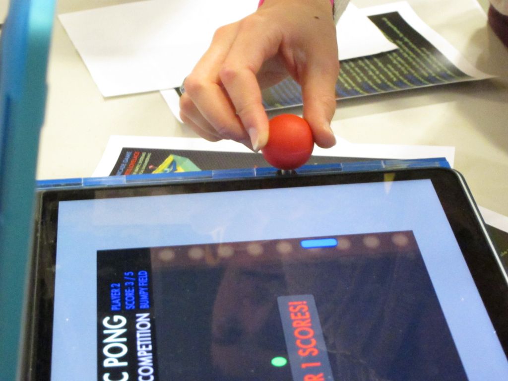
A fully-functional tabletop prototype of HAPTIC PONG was built consisting of two linearly sliding haptic paddles with laptop computer screen flat down between them. Each paddle is controlled by an Arduino and displays force feedback based on hitting or missing the virtual ball as well as changes to the virtual environment, such as æsticky field' or æspringy paddle,' which players can implement by sending the ball towards power-up capsules. The computer screen illustrates the score, ball and paddle location, and field conditions via a program running on the Processing platform.
During the Haptics Open House at Stanford on 12/11/12, HAPTIC PONG was voted the 'most fun' demonstration and prompted a series of interesting conversations about force rendering with the students that tried it.
On this page... (hide)
Introduction
HAPTIC PONG was conceived as an engaging way to promote teaching physics and basic control concepts to high school students. The game was motivated by the philosophy that learning is facilitated when students are having fun, competing, or otherwise invested their learning. Not only do students get more tactile feedback than other learning games, but they also get to experience force concepts in a unique way. HAPTIC PONG uses touch feedback first to engage, and eventually to educate.
By playing a game that illustrates forces, students are able to experience concepts such as proportional spring force and damping. In working with the re-programmable platforms of Processing and Arduino, this initial work builds the foundations for a more interactive, configurable version of HAPTIC PONG. This next iteration would build upon the momentum of fun, arcade-style competition and allow students to quantitatively adjust the parameters of the haptic effects.
In addition to the game interaction aspect, this project also comprised the development of a linear, 1-DOF version of the Haptic Paddle, a tried-and-true education tool. Though the Haptic Paddle has been shown as a powerful tool to teach undergraduate dynamic [source], the reality is that it works in cylindrical coordinate space, while most physics and dynamics concepts are taught at the basic level first in linear (then cartesian planar) space. In attempting to bring the Haptic Paddle to linear space, this project has pushed this educational tool forward as well.
Background
Since HAPTIC PONG was envisioned as a virtual pong game using a novel linear 1-DOF haptic device, extensive research was performed on similar topics in order to get a better feel for what others had previously done. Research was divided into two categories: Linear 1-DOF devices and force-feedback gaming.
First off, a list of papers was compiled, consisting of different ways to design 1-DOF linear devices. For HAPTIC PONG, use of a rotary motor instead of a linear actuator was beneficial. Besides the fact that nice rotary motors were easily accessible, linear actuators had some disadvantages including a poor volume to range of motion ratio [1]. Therefore research focused on different mechanisms, which could translate rotational actuation into linear motion.
Much of the previous research was summarized by Joinie-Maurin et al [2]. who described pros and cons of four different linear mechanisms: 1) rack and pinion mechanism; 2) ball-screw mechanism; 3) cable mechanism; 4) slider-crank mechanism. They quickly ruled out 1) because of low efficiency and 2) due to it not being back drivable enough. Then, they looked in depth at four different 4-bar mechanisms: Hoeken's, Roberts, Chebychev, and Chebychev V mechanisms. They simulated each mechanism and drew the linkage positions at it's minimum and maximum positions. They ended up designing a Hoeken mechanism due to its higher tip force and large workspace.
However, the Roberts mechanism was ideal for HAPTIC PONG due to its large region with minimal deviation from linearity and its rectangular layout. In addition, the current Haptic Paddle could be modified and used as a linkage in the Roberts mechanism providing useful crossover between previous work by Okamura et al.[3].
Research into haptic gaming looked mainly at devices which incorporated force-feedback rather than vibrotactile effects. Park et al. [4] built a haptic dial to interface with a PC-based Breakout style game. This paper was useful because it described some of the forces and effects that they chose to render (time-dependent, location-based, movement-based, and angle-based), and how they integrated these effects into their gameplay. For HAPTIC PONG, velocity-dependence and directional-bias were added to their list of haptic effects for.
Other pertinent research included "Haptic Battle Pong" by Morris et al.[5] who designed a networked version of a pong-style game using a current 6-DOF consumer haptic device as a joystick. Because of the challenges with networking, the authors used an algorithm that allowed the main virtual-interaction simulation to be switched between each player depending on who was next to interact with the ball in order to ensure accuracy during the virtual interaction itself. Because of similar issues with communication between two haptic devices, HAPTIC PONG makes use of this information sharing method during haptic interactions.
Methods
A fully-functional prototype of HAPTIC PONG was built using two identical haptic linear paddles. Each paddle was driven by an Arduino Uno controlling a Maxon RE25 motor with a 500x4 ticks/revolution quadrature encoder via an Ardumoto motor control shield.
Each Arduino drove haptic feedback at 500Hz and communicated with a Processing application running on the laptop via 28800bps serial connection. The Processing application displayed the virtual environment and managed communication between the two Arduino systems.
In addition to simulating ball impact and buzzing when users missed the ball, the prototype implemented seven virtual environment features. These features, spefically the 'autopilot,' 'springy paddle' and 'sticky field' mode, were designed to prompt conversations with high school students about the physics calculations involved in simulating a virtual environment.
HAPTIC PONG consists of 3 major design components: the mechanical system, the embedded program running on the Arduinos, and the Processing program running on the laptop. The mechanical and embedded systems interface via a PWM-controlled motor and quadrature encoder, and the embedded and PC systems interface via serial communication. Each of the three designs and the serial interface are described below.
Mechanical Design: Two Linear Approximator Haptic Paddles
The linear paddles developed for HAPTIC PONG owe much to the Haptic Paddle first developed at Stanford and Johns Hopkins [3] and improved upon elsewhere. The design shares with its predecessor laser-cut construction and a sector pulley with a tensioned capstan cable drive.

The HAPTIC PONG physical prototype was designed in SolidWorks and fabricated from the final model shown above (click on the image for a higher-resolution render). The paddles are enclosed in a box 10.0" x 17.0" x 5.0" tall.
Four-Bar Linkage
The chief innovation in the HAPTIC PONG paddle is the use of a weight-balanced four-bar linkage in a Roberts Mechanism configuration to approximate linear motion. In each four-bar mechanism, the large horizontal piece of acrylic (the 'field') anchors the first base (horizontal) bar, the two half-inch acrylic parts formed bars 2 and 4, and the triangular piece that formed the fourth bar also held the knob.
The linkage sizes in the fabricated prototype are as follows:

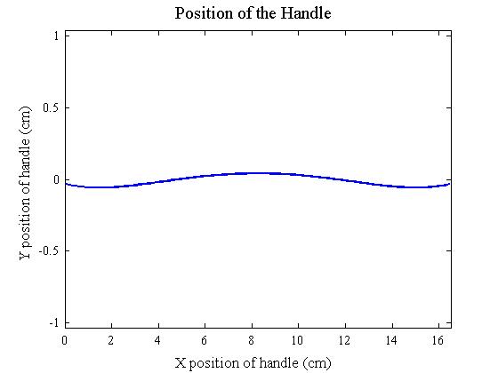
These four-bar linkage dimensions provide an excellent approximation of linearity over the 6.5" of slot length, as analyzed in a MATLAB script (attached in the Files section) and shown below:
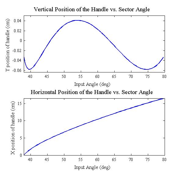
The linkage results in a symmetrical, near-linear motion path with less than 1.2 mm deviation from horizontal:
Fabrication
All iterations of the HAPTIC PONG mechanism, both individual paddles and the integrated playing field, were laser cut at the Stanford Product Realization lab out of clear acrylic. All acrylic was nominal 1/4", measured at .236", with the exception of the linkages rendered in green above. These linkages were cut out of nominal 1/2" acrylic, measured at .491".
All laser-cut parts were offset by the measured kerf of the laser. This provided .001" to .002" precision for part overall dimensions. The kerf was measured by cutting a .750" x .750" square out of acrylic and measuring the actual overall dimensions.
Internal holes were undersized and drilled out using standard 1/8" and 1/4" drill bits to prove press fits for the 1/8" precision shafts and 1/4" OD Rulon bearings. #6 Clearance holes in the sector pulleys for mounting the capstan drive cable were marked with calipers and drilled by hand into laser-cut surfaces.
Each four-bar mechanism used four 1/8" precision shafts. The shafts were press-fit into bars 2 and 4 and slipped into Rulon bearings press-fit in the field and knob bars. Horizontal parts with additional Rulon bearings reinforced the field and kept the 1/2" parts vertical. With shaft collars spacing the 1/2" parts off the field, there were no issues of cantilever interference.
The finished prototype can be seen below.

Each HAPTIC PONG handle is a 1.25" diameter red polypropylene ball knob, chosen for user comfort and familiarity. In order to prevent downward cantilevered torques on the four-bar linkage, the handles are vertically supported with shaft collars (and nylon washers to prevent excessive friction).
The knob assembly is shown below.
A laptop screen (specifically a 15" Macbook Pro) was inverted and placed on top of the acrylic box to give players an intuitive virtual paddle control experience.
Arduino Embedded Software: Haptic Loops and simulating Pong
The Haptic Pong Arduino code is found below in the Files section. It is broken into several modules:
- An initial page of definitions and generic helper functions
- Processing field size constants
- Communcations constants
- Game physics constants
- double mapfloat(double x, double in_min, double in_max, double out_min, double out_max)
- String intToString(int num,int digits)
- void setPwmFrequency(int pin, int divisor)
- Setup_Functions
- void setup()
- void resetBall()
- Loop containing the main loop function:
void loop()
{
  // Check Events and output to serial as appropriate:
  if (ScoreFlag == true)
  {
   outputScore();
   ControlState = WAITING;
   ScoreFlag = false;
  }
  else if (HitFlag == true)
  {
   outputHit();
   ControlState = WAITING;
   HitFlag = false;
  }
  else
  {
    outputPackageToSerial();
  }
  // Deal with incoming serial events:
  if (newEventString == true)
  {
    handleEvent();
    newEventString = false;
  }

}
- HapticLoop containing the interrupt driven (500Hz) Haptic Loop:
void hapticloop() { int StartTime = micros(); // Monitor loop execution time... *** calculatePaddlePosition(); // Get y calculatePaddleVelocity(); // Filter ydot calculateHapticEffect(); // Calculate force to display moveBall(); // Update field conditions if(HitFlag==false)checkForHit(); // Check for a new hit ActuateForce(F_a); // Convert actuated force to a motor torque ElapsedTime = micros() - StartTime; // ***... to ensure loop runs fast enough! HapticTime += dT; // Used for time-based haptic effects }- void calculatePaddlePosition()
- void calculatePaddleVelocity()
- void ActuateForce()
The function calculatePaddlePosition reads the encoder ticks, then uses 4th-order polynomial mapping (developed in MATLAB using a script attached in the Files section) to calculate the physical position (called HapticPos) as well as its derivative to calculated the Jacobian at the instant of measurement.


calculatePaddleVelocity uses a discrete low-pass filter to keep a live calculation of velocity. This is used in control laws, primarily to display damping forces.
ActuateForce multiplies the desired force by the instantaneous Jacobian of the system to determine a toque to express, then calculates the appropriate duty cycle to output. This method leverages the square-root relationship between duty cycle and torque for the Maxon RE25 as measured by ME327 Teaching Assistant Nick Colonnese.
- Haptic_Effects containing a decision tree and individual render functions:
- void calculateHapticEffect(), which calls a combination of the following:
- void moveSideWalls()
- void bumpyField()
- void repelBall()
- void potholeValley()
- void tiePaddleToCenter()
- void linearDamping()
- void heavyDamping()
- void followBall()
- void renderImpact()
- void renderBuzz()
- double ball_y_toHaptic(), a helper function to map ball position to its physical counterpart
- Gameplay, functions to move the virtual ball around the field:
- void moveBall()
- void detectWallCollision()
- void checkForHit()
- Paddle_Serial: Read/write functions:
- void serialEvent(), an interrupt handler that stores inString and raises a flag
- void handleEvent(), parses inString during the main loop
- void outputPackageToSerial(), sends paddley and ballx & bally to Processing
- void outputScore(), sends a score message to Processing
- void outputHit(), sends x,y, xdot, ydot to Processing
Processing Program: Displaying Haptic Pong
// Like the Arduino program, the Processing program was broken into readable modules and is available for download in the Files section, below. The modules were:
- An introductory page with constant definitions:
- Haptic effect constants and variables
- Game control state variables and definitions
- Graphics constants
- Gameplay variables
- void KeyPressed(), a Processing interrupt to handle key presses (used spacebar to reset the game as well as <> and [] to cycle through effects for each paddle
- Draw_etc containing the main draw loop and helper functions:
void draw() { drawBackground(); updatePowerUps(); drawHapticGraphics(); drawPaddles(); drawBall(); RunControlSM(); // Runs the main state machine blink(); // Cycles an oscillator for blinking text brightness updateScoreboard(); // Redraws every 10 frames }- void updatePowerUp()
- void updateScoreboard()
- Setup containing the one-time setup() function
void setup() { fillArrays(); setupSerial(); initializeGraphics(); resetGame(); }- void fillArrays()
- void setupSerial()
- void resetGame()
- void reconnectSerialPorts()
- ControlSM containing the main control State Machine:
- void RunControlSM()
A state chart of the main program is shown below.

- ReadSerial containing handler functions
- void serialEvent(Serial thisPort), a serial event handler service
- void HandleHit(int whichpaddle), processes hit messages
- void ReadData(int whichpaddle), parses serial data from paddles
- WriteSerial containing functions to write to each paddle
- void sendNewBall()
- void transferBallTo(int transferToWhich)
- void sendPowerUpToArduino()
- void transferBallTo(int transferToWhich)
- void turnOffHaptics()
- void sendEffects(int Effect, int whichPaddle)
- String intToString(int num,int digits)
- Drawing containing functions to draw game elements (Illustrated in 'Haptic Effects' below):
- void initializeGraphics()
- void drawBackground()
- void drawPaddles()
- void drawBall()
- void drawHapticGraphics()
- void drawPowerUp()
- void drawAutoPilot(int whichPaddle)
- void drawSlime(int whichPaddle)
- void drawPotHole(int whichPaddle)
- void drawSideWalls(int whichPaddle)
- void drawBumps(int whichPaddle)
- void drawSpring(int whichPaddle)
- void drawForceField(int whichPaddle)
- void drawCleanup(int side)
- TextDisplay containing functions to write to the screen:
- void titleText()
- void updatePlayerStatus(int player)
- void blinkFeel(), blinks the word 'Feel' in the tagline FEEL THE COMPETITION
- void showScore()
- void showWin()
- void showGetReady()
- void blink()
Managing Serial Communication
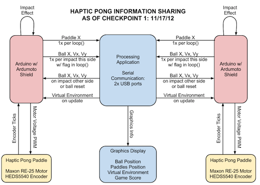
In order to manage communication between the laptop PC and two Arduinos, the HAPTIC PONG system implemented the following information sharing dynamic:
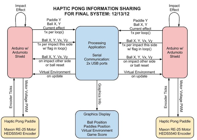
This method requires each Arduino to keep track of and send its own copy of the ball's location. The Processing application drew the ball corresponding to which Arduino 'owned' the ball. For the purposes of rendering a realistic environment, the Arduino corresponding to the paddle that t he ball was approaching acts as the owner. When an impact is detected, the Arduino sends the laptop the relevant information to transfer control. When a control transfer is confirmed, Processing switches which Arduino owns the ball.
The messages that were sent from each Arduino were generated as Strings and the protocol was developed as follows:

In this way, the Processing application can determine which Arduino is in control of the ball, as well as take the ""Hit"" collision data and send it to the other Arduino as quickly as possible. The Processing application also able to makse sure the haptic effects have been changed during gameplay by comparing its desired effect and the effect that each Arduino is currently running. Using a similar String procedure, Processing outputs three different types of packets: 1) "N"ew ball information during reset, 2) "B"all information after a hit, and 3) "E"ffect that the Arduino should render.
Keeping Strings the Correct Length
This String procedure was facilitated by a custom function, intToString:
//intToString:
// Takes a signed integer and converts it to a string of specified length.

String intToString(int num,int digits)
{
  String str;
  int max_positive = 1;
  int min_negative = 0;
  if(digits>4) digits = 4;
  for (int i = 0; i<digits; i++)
  {
    max_positive *= 10;
  }
  min_negative = 1-(max_positive/10);
  max_positive -= 1;
  if (num >= max_positive) num = max_positive;
  if (num <= min_negative) num = min_negative;

  if (num < 0)
  {
    str = String(abs(num));
    while(str.length() < digits-1)
    {
      str = '0' + str;
    }
    str = '-' + str;
  }
  else
  {
    str = String(num);
    while(str.length() < digits)
    {
      str = '0' + str;
    }
  }
  return str;
}
Error Swallowing:
The team experienced early on the consequences of serial communication not being 100% reliable: the Processing application would suddenly quit after just a few hits. The team initially reset the Arduino serial communication in between every game to prevent overloading the serial ports. However, this proved unnecessary with the incorporation of error 'swallowing' functions. These features, which allowed the Processing program to continue running when miscommunications to occur, vastly improved performance.
\\ The code snippet that accomplished this within the serialEvent() handler function was:
void serialEvent(Serial thisPort)
{
  ...
  catch (Exception e){
    println("Serial-Event Error!! caught");
  }
}
Haptic Effects
The following is a summary of the physical rules used to generate the haptic effects. Each in-game power up is accompanied by a graphic of that haptic effect acting on the red paddle (Player 1).
Springy Paddle: F = kspring * (ycenter - ypaddle)
This is a linear spring.

| 
|
Sticky Field: F = - bheavy * vpaddle
This is strong linear damping.

| 
|
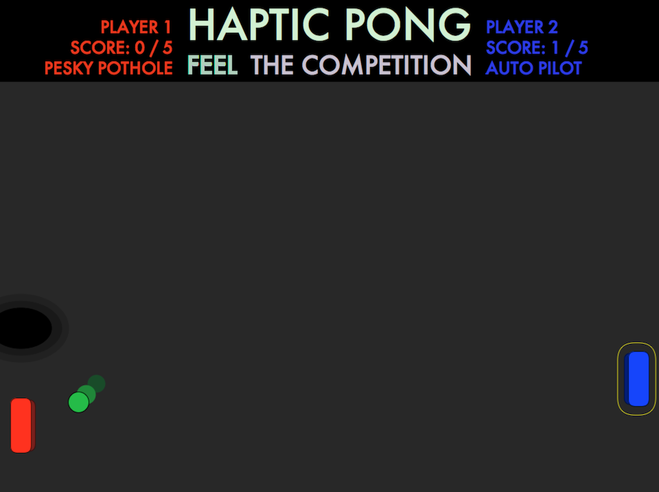
Pesky Pothole: F = -c * sin(π * (ypaddle - yhole) / rhole), if ypaddle is within rball of rhole
This is a sinusoidal valley.

| 
|
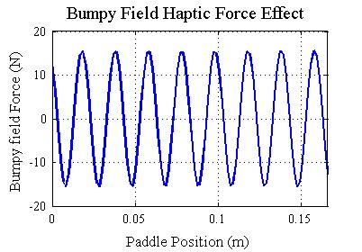
Bumpy Field: F = c * sin(π * (ypaddle - offset) / rbump)
This is a sinusoidal pattern of less severe valleys and bumps.
| 
|
AutoPilot: F = kauto * (yball - ypaddle)
This is simple proportional rule control.

| 
|
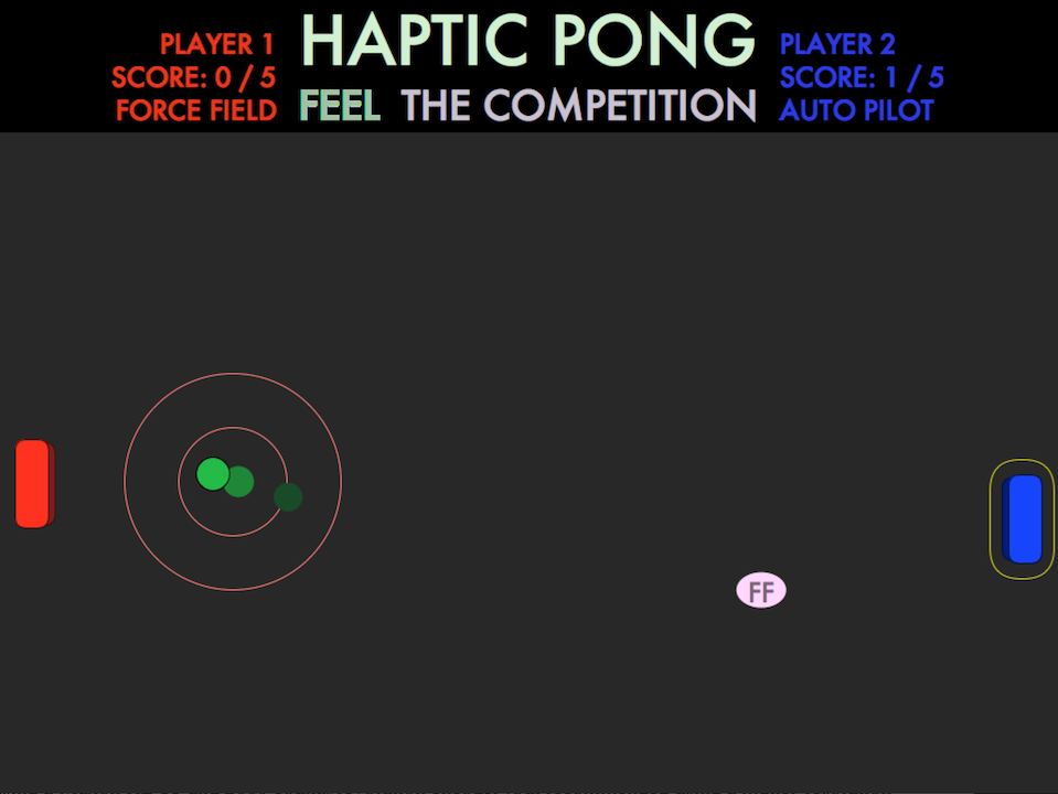
Force Field: F = Fmax * (1 - dist / rFF ), away from ball,
if dist is within rFF, where dist is the xy distance between ball and paddle
This is a cone-shaped field of repulsion.

| 
|
Collision with ball: Magnitude influenced by x-velocity on impact

Buzz after score: always the same

Results
Educational Results
HAPTIC PONG made its debut on December 11, 2012 as part of the Haptic Open House, an event for high school students and visiting scholars at Stanford University. The hands-on demonstration for students was accompanied by a a poster:

The HAPTIC PONG team demonstrated the basic gameplay and introduced several haptic effects for each group of students that approached the booth. Though some students were only interested in gameplay and outscoring their friends, several demonstrations led to in-depth conversations about the rules behind the forces rendered, as well as how the system works.
In addition, HAPTIC PONG was voted the 'most fun' demonstration in student sticker voting (other categories were 'most educational' and 'most creative,' and a few votes were earned in these categories as well).
Design Results
The linear approximator haptic paddles of HAPTIC PONG were able to successfully render forces at 500Hz by live-calculating a Jacobian based on a fourth-order polynomial. These forces displayed a series of compelling virtual environments which were coupled with visual representations on a laptop PC monitor. The successful implementation of this system paves the way for future work with linear haptic paddles and interactive visual-haptic displays of virtual environments.
Future Work
HAPTIC PONG was designed as an educational game, and future work to evaluate its strengths as an educational tool would be interesting. However, this work could not occur until the system is documented and made scalable to a classroom environment. Before this happens, a series of improvements could be made to the system:
Software Improvements
HAPTIC PONG shows tremendous potential as a teaching tool. One of the original goals of the project was to give students a chance to experiment with control laws by quantitatively adjusting the sample virtual environments and observe how the new system feels (or behaves on its own, in the case of the auto-pilot effect. Future work can and should integrate a mode in which students can view and edit the control laws behind these effects. This could also yield a stand-alone control system application for a standard (not linear) Haptic Paddle.
Mechatronic Redesign
The current prototype of HAPTIC PONG suffers from an occasional issue in which a 'hit' message is not received right away. In this case the ball jumps as display control switches from one Arduino to the other. This and a few other reliability problems could be mitigated by consolidating the entire mechatronic system to a single processor.
The Arduino Uno is able to support two motors via PWM, but the Ardumoto H-bridge is unable to source enough power to two motors on at once. This problem could be solved by setting two motors, capped at 50% duty cycle, 180 degrees out of phase with each other. Setting these phases would require changing registers on the ATmega chip rather than relying on Arduino libraries.
On the other side, the Arduino Uno may not have enough interrupt pins to read both quadrature encoders reliably while running the rest of the code. This requires investigation into the need for an upgrade to the Arduino Mega board and a non-Ardumoto H-bridge solution.
With any move away from the basic Arduino Uno and off-the-shelf parts, the haptic linear paddle becomes less accessible as an educational tool so the tradeoffs must be evaluated.
Mechanical Design Iteration and New Features
The chief disadvantage of the linear paddles used in HAPTIC PONG is the large variance in Jacobian across the paddle motion space., and the resultant inconsistency in maximum force that can be rendered. A more thorough, analytical study of the Roberts mechanism kinematics could yield a more optimum set of parameters for a linear approximation system.
The system could be made generally more robust, with specific attention given to the following items:
- a more slip-proof capstan drive, perhaps fabricated from a screw shaft rather than 3D printed
- a more permanent acrylic frame
- a superior mounting mechanism for the PC monitor
Ideally, a new mechanical frame design would incorporate a dedicated inexpensive PC monitor for the display of multiple applications on HAPTIC PONG hardware.
Files
The files used to get HAPTIC PONG up and running can be found below. As the acrylic parts were laser-cut using a custom kerf calibration for .001" precision, it is recommended that further investigation start directly with the CAD model and offset the outlines of laser-cut parts as appropriate for the laser cutter and material used.
- The Arduino program can be found here.
- The Processing program can be found here.
- CAD files (Solidworks Education 2013) can be found here.
- A list of parts used and their costs can be found here.
- Polyfit + Jacobian MATLAB code: Analysis & Plotting.
- Four-bar linkage MATLAB code: Analysis & Plotting
- The HAPTIC PONG Haptics Open House Poster can be viewed here.
Reference
[1] L. Barbķ, B. Bayle, J. Gangloff, M. de Mathelin, O. Piccin. "Design and Evaluation of a Linear Haptic Device." IEEE 2007. International Conference on Robotics and Automation, 10-14 April 2007.
[2] M. Joiniķ-Maurin, L. Barbķ, O. Picnic, J. Ganglof, B. Bayle, and R. Rump. "Design of a Linear Haptic Display Based on Approximate Straight Line Mechanisms." IEEE/RSJ International Conference on Intelligent Robots and Systems, October 18-22, 2010.
[3] Okamura, A. Richard, C. Cutkosky M. "Feeling is Believing: Using a Force-feedback Joystick to Teach Dynamic Systems." Journal of Engineering Education, July 2002.
[4] Wanjoo Park; Laehyun Kim; Hyunchul Cho; Sehyung Park. "Design of Haptic Interface for Brickout game." IEEE International Workshop on Haptic Audio visual Environments and Games, 2009.
[5] D. Morris, N. Joshi, and K.Salisbury. "Haptic Battle Pong: High-Degree-of-Freedom Haptics in a Multiplayer Gaming Environment." Experimental Gameplay Workshop, Game Developers Conference 2004.
Appendix: Project Checkpoints
Project checkpoint posts are archived below.
!!!Checkpoint 1
We both gave our paper presentations this week, so we made sure not to be too ambitious with Checkpoint 1. That said, we got off to to a good start with our initial design of both hardware and software. Our goals for this checkpoint were:
- Preliminary design (hardware and electronics)
- Play with Processing & Graphics
We were satisfied with what we accomplished for the first checkpoint. We've divided this post into Hardware Design and Software Design, as seen below.
Preliminary Hardware Design:
We 're developing a linear version of the 1-DOF Haptic Paddle. When the design is finalized, we'll build one for each of the 2 players. The major components of the hardware design are:
- Position Sensing
- Force Feedback
- Linear Motion
In an effort to accelerate the implementation process and focus on user (student) experience, we decided to use one class-provided Maxon RE25 Motor with HEDS5540 Encoder for each Haptic Pong Paddle. With that decided, the challenge lay in implementing a linear version of the classic rotary Haptic Paddle. We have two approaches in mind for this:
1. Roberts Mechanism (Four-bar linkage with near-linear motion)
Our literature review yielded a couple of papers with linear haptic interface prototypes from the EAVR (Automation, Vision and Robotics Team) at the University of Strasbourg. In one paper, the authors discuss Design of a Linear Haptic Display Based on Approximate Straight Line Mechanisms. They used the Hoeken's mechanism for their prototype, but the Roberts mechanism (one of the other mechanisms they considered) fits within our envelope of motion better.
As such, we began a design of a Roberts mechanism that could translate Capstan drive into linear feedback in Solidworks:
Note that the motor is oriented vertically, and the either Haptic Pong field must therefore be raised several inches above a solid table surface.
2. Linear Slide Capstan
During our proposal review, Allison suggested mounting a capstan drive on a linear slide bearing. We completed a preliminary design in which the Maxon motor is mounted on a solid block that also includes the user's handle, and the capstan drive cable is attached to the fixed outer shell. This design can be seen in the following video:
This design has the advantages of a constant ratio between encoder ticks and motion in X, and a more compact height profile. However, the location of the maxon motor on the moving block is not ideal for robustness of electronics. In addition, the linear slides, available from McMaster-Carr, are fairly expensive compared to the laser-cut parts, pivot shafts and bushings we could use to implement the Roberts mechanism design.
As we continue work on mechanical design, we'll decide on a path for linearizing the paddle and move forward down that path for the next checkpoint.
Preliminary Software Design:
We're planning on having Processing talk to two Arduinos via two serial connections over USB in the laptop that's running the Processing application. There are several software processes that must occur in parallel for Haptic Pong to work:
- Processing displays the paddle and ball positions and keep score
- Processing sends ball and environment status to Arduinos
- Arduinos sense position of each paddle and send it to Processing
- Either Processing or Arduinos must detect whether the paddle successfully hits the ball
The decision of which device handles collision detection is not finalized yet. Right now, we think that it makes sense to have each Arduino completely aware of the state of the virtual environment, and have it pass the new ball trajectory to Processing, which will in turn pass it to the other Arduino, upon impact. We came up with this strategy based on position information handling a networked Haptic game, Haptic Battle Pong.
A diagram illustrating our event and information handling strategy follows:
We set out building our graphics and game environment for testing in Processing. We started by building up a simple Pong environment, then integrated serial reading with a Haptic Paddle. Initial integration can be seen in the video below:

Checkpoint 2
Since we were away from campus for Thanksgiving break, we decided that it would be best to set high goals for the software and graphics side of the system. Also, we wanted to build and test an initial physical prototype for our game. Our goals for this checkpoint were:
- Be able to reliably communicate between Processing and Arduino
- Compete basic graphics and start on game-play add-ins
- Build working mechanical prototype
- Stretch Goal: Have one paddle working very well or two paddles working with a few kinks
Even though we came across some potential difficulties, we were overall satisfied with the progress through this checkpoint. As we did for the previous checkpoint, we divided this post into Hardware Design and Software Design/Communication.
Mechanical Hardware Design:
We decided to move forward with the four-bar linkage option from Checkpoint 1. We concluded that this design would be more feasible and novel to prototype.
First, we added a great deal of detail to the Roberts mechanism design to make it useful and manufacturable. We built up a sturdy enclosure to contain the electronics and hold the mechanism robustly. In doing so, we took some cues from the very reliable Haptic Paddle design. Since the capstan drive portion of our linkage is essentially a Haptic Paddle rotated 90 degrees, we verified that our Haptic Paddles worked well without undue friction or binding when we turned them sideways. Since the hardware for the Haptic Paddle was so reliable, we ordered more Rulon sleeve bearings, stainless steel 1/8" shafts, and steel shaft collars to hold parts in place, from McMaster-Carr. We added the hardware to our CAD model, and re-accounted for component spacing to ensure a strong, reliable mechanism. Our improved design with 2 paddles, hardware, and an enclosure can be seen below.

We picked up some 1/2" and 1/4" clear acrylic from TAP Plastics and completed the laser cutting needed to build a working paddle in the PRL. We took the time to account for laser kerf and measured exact material thickness, so the parts fit together really nicely.

We also began construction and secondary machining processes (e.g. drilling holes for the capstan cable mount screws), but unfortunately, the McMaster-Carr order hasn't arrived as of Friday night, so we haven't been able to integrate the laser-cut parts into a fully working prototype. We are very confident the next prototype will be successful. We plan to work hard on ensuring this between now and Checkpoint 3.

Software and Communication Design:
Arduino -> Processing
In order to be able to successfully implement haptic force feedback (the main distinguishing feature of our version of Pong), we determined that we must keep track of the ball's position on the Arduino rather than in Processing due to the time delay that would occur between collision detection and rendering the haptic force to the user. In doing it this way, we must send the ball position (both x and y coordinates) as well as the paddle position as fast as possible to Processing in order to achieve adequate graphic display.
So far, we have written successful protocols for being able to successfully communicate between the mechanical paddle (with an Arduino) and the graphical display (using Processing). Our method involves sending a String consisting of xxxyyyzzz, where xxx is the vertical position of the paddle, yyy is the horizontal position of the ball, and zzz is the ball's vertical position. This protocol was easy to implement due to Processing's "substring()" function, and runs fast enough for our use in this project. The most important fact here is that we add a leading zero to each value if the length is less than the desired 3 characters, so that we consistently identify the correct values in Processing. We have this method working very effectively for a one-paddle system.
In order to connect 2 paddles for our game, we have to be able to read-in the positions of both paddles simultaneously. Currently, we are able to communicate with the second paddle using another Arduino, however we have run into challenges with Processing distinguishing between the 2 serial ports. At this point, it seems one of the serial ports has some sort of priority during a serial event occurring. We are checking to see if this mistake is a hardware issue or a software one, but since we have for the most part copied the protocol from Processing:Examples:Library:Serial:SerialMultiple we are leaning toward a hardware issue and may try running the same code on another computer or USB port. From previous experience, we know that it is possible to run 2 Arduino's from one computer, but we do not know for sure whether we can communicate with them as we want to for this project.
Also, as previously discussed in Checkpoint 1, we created a "control state" in each Arduino in order to distinguish which one currently should control the ball's movement. After Arduino "A" records an impact with the ball, it gives control of the ball's movement to Arduino "B" by sending the ball x, ball y, ball x_dot, and ball y_dot, since Arduino "B" will now be the next to hit the ball (or to miss and record a score). In doing this, we hope that we will be able to render the haptic forces more realistically. As of Checkpoint 2, since we have been unable read the handle positions of the two paddles at once, we have been unable to test the realism of the complete gameplay, and the time delays that may be caused during the switch of the control state to the other Arduino.
If we are unable to get these challenges worked out, we are fairly confident that we will be able to run our two motors (and therefore our 2 paddles) on one Arduino. We would just need to add the other paddle position to our current String being sent to Processing, and double some of the code for reading another encoder and outputting commands to another motor. This would successfully remove the need to read two Serial ports at once, and also to switch game control between two Arduinos.
Processing->Arduino
Since a main feature of our Pong game will be the changing haptic effects enabled during gameplay, we also needed to create a protocol for sending commands from Processing to an Arduino. Because of the different functions available to the two languages, we were unable to use the same String.substring() command which made the previous communication possible. Instead, we decided to send a packet consisting of two ints over Serial in order to change the state of the gameplay in the Arduino environment. We also wanted to use this communication to initialize the gameplay (which only needs to start when the Processing graphic window is opened).
Thus, our protocol is as follows: if the first int equals 0, then the second int equals a number corresponding to the desired haptic effect (friction, spring, etc); and if the first int does not equal zero, then the two ints represent the x and y velocities of the ball respectively (the variables needed to start the ball moving). Therefore, we could randomize the initial conditions of the game, i.e., which direction the ball is going to start out in. We have tested the protocol over Serial, and we have been able to reliably start the ball rolling so to speak with Processing and can quickly change haptic effects in a similar way.
Gameplay
As of Checkpoint 2, we do not have a full list of the haptic effects that we will implement during the gameplay, but they will be relatively straight-forward with implementation similar to our previous work in assignment 4 for ME 327. We would also like to visual display each haptic effect during gameplay.
Overall, we feel very confident in where we are with the software and electronics needed for a successful project, and we have a feasible backup plan if we are unable to get our somewhat complicated communication system working like we've laid out for Checkpoint 2. If interested, the current progress of our code can be found here:
Checkpoint 3
Since the two of us have finals in between Checkpoint 3 (Dec. 7) and the final presentation day (Dec. 11), we created strict goals of having the main features of the project completed with only a few gameplay modifications to implement after Checkpoint 3. Our goals for this checkpoint were:
- Fully integrated system, most power-up features
- Decide which "reach features to implement"
Although we ran into some challenging bugs during the integration of the system, we finally were happy with the reliability of our communication between the two Arduinos and Processing.
Software and Communication Design:
At the end of Checkpoint 2, we were uncertain whether we would be able to implement the communication as we had initially planned out; however, after a few sleepless nights, we can safely say that we have been able to implement the original design (running 2 Arduinos with a motor/encoder on each)!
We had a major breakthrough with some of the errors we were running into when we figured out a way to catch and throw SerialEvent errors so that the gameplay would not stop every time the Serial port had an issue. Thus, since we are still able to communicate at high baud rates, an occasional bit error does not perceptively affect gameplay. Also, when we want to reset the ball after a player has scored, we found it much more reliable to stop Serial communication with the Arduinos, and then begin new communication rather than clearing the Serial ports. This also served to reset the Arduinos so that the gameplay effects and state modifications would be set back to default.
During our in-depth exploration of the communication world, we decided to clean up the way we were implementing control states for each paddle during gameplay. The main change was creating intermediate states called "A to B" and "B to A" which allowed us to correctly display the ball during transition from one Arduino controlling the ball to the other one.
We compensated for the 300 millisecond-long lag involved in passing control of the game from one Arduino to the other by speeding up the first 30 milliseconds of operation after new ball update to 10x speed. This hugely improved the feel of gameplay.
Final Mechanical Design:
We made good use of the PRL LaserCamm and Room36 power tools in machining the full-sized, 2-player version of the Haptic Pong physical interface out of clear acrylic. We laser-cut the structural pieces to precise press fits into each other, and then drilled out press fit holes for Rulon bearings and 1/8" precision shafts. We used a 2-revolution wind on each capstan drive. We are very pleased with the performance, and look forward to adding bright grip knobs!
Rendering Haptic Effects:
Now that we have successful communication, we started working on implementing simple haptic effects into the gameplay.
Though our mechanical design accomplishes near-linear motion very smoothly, we needed to put some thought and programming into rendering forces accurately since motion is nonlinear with respect to the capstan sector angle.
Rather than live-calculate the kinematics of the Roberts mechanism, we chose the computationally advantageous method of calculating both x and J as a polynomial function of encoder ticks. We took physical measurements every 2cm of our paddle slots and recorded the encoder counts, then wrote a MATLAB script to generate a 4th-order polynomial fit to map encoder counts (q) to meters(x).

As the plot shows, we mapped the handle position into meters so that we could calculate forces and torques in known metric values. This allowed us to live-calculate the Jacobian of our 1-DOF system as well, using the derivative of the mapping polynomial.
We also stored the paddle position in terms of pixels so that we could easily compare its value to the virtual ball and transfer both values to Processing. Since our paddles are flipped 180 degrees in physical space but mirrored in our Processing app each paddle must map its location differently, as shown in the code snippet below:
// Polynomial Fit of q(encoder ticks) to x
const double a4 = 2.6108*pow(10,-17);
const double a3 = -2.7774*pow(10,-13);
const double a2 = 1.2844*pow(10,-9);
const double a1 = 1.2874*pow(10,-5);
const double a0 = 9.5836*pow(10,-5);
ģ
// Calculate Position:
HapticPos = a0 + a1*q + a2*q*q + a3*q*q*q + a4*q*q*q*q;
// Calculate Jacobian:
JacobianTicks = a1 + 2*a2*q + 3*a3*q*q + 4*a4*q*q*q; // meters/sec per tick/sec
Jacobian = JacobianTicks * 2000 / PI; // meters/sec per radian/sec
// Map to pixels:
if (paddle == PADDLEA)
{
paddlePos = mapfloat(HapticPos,0,physical_slot_length,paddle_ymin,paddle_ymax);
}
else
{
paddlePos = mapfloat(HapticPos,physical_slot_length,0,paddle_ymin,paddle_ymax);
}
Once we got this working, it was simple to implement accurate force rendering:
float Tau_motor = f_render * Jacobian;
We verified the force rendering with a control law that tied the paddle to the middle of the slot with a linear spring, and confirmed that the force response was symmetric even though the kinematics were not.
Integration:
We'll let the following video speak for itself!
Reach Features:
We had proposed the following reach goals:
- Iterate the design of the paddles to cost less than $50 each (no Maxon motor-encoders)
- Convert the linear paddle design into a kit for educators or students
- Allow students to program and test their own autopilot
- Increase the graphical resolution of Haptic Pong to increase student engagement
- Investigate a remote / networked version of Haptic Pong
However, integrating Processing with 2 Arduinos with high-frequency 2-way communication proved plenty difficult on its own. As such, we'll be limiting the scope of this project to making sure the system is up and running for the Haptics Open House demo, and making sure that both our software and mechanical design are accessible and well-documented for future work by educators or students.