

Khandelwal Khan Tin

Caption:
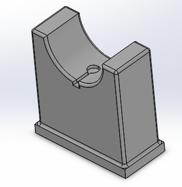
CAD Design of Haptic Bracelet Assembly.
Wearable Haptic Bracelet for Safe Navigation
Project team member(s): Anuj Khandelwal, Aadil Khan, Tin Jing Jie
This project laid the groundwork for a wearable haptic pathfinder, which aims to allow users such as cyclists to navigate to their desired destination through haptic feedback. For cyclists, the movement of eyes and attention from the road to refer to traditional GPS maps is often an unsafe activity, and increases the probability of an accident. By developing a wearable haptic bracelet which provides vibration and force feedback to the user based on the degree and direction of turning required and his/her distance from the junction, this allows users to focus their attention solely on manouvering around obstacles on the road such as vehicles and pedestrains, thereby increasing user safety. To achieve these goals, the team developed a base-mounted proof-of-concept device through which users were provided navigation for on-screen avatar.
On this page... (hide)
Introduction
The haptic device that our team will work on is based on the concept of a wearable haptic pathfinder. The original concept aimed at guiding users to a destination based on kinesthetic or force feedback on their wrist from a wearable bracelet or band that is equipped with motors and microcontroller. Depending on the degree of turn that needs to be taken, an appropriate force would be generated in that particular direction. Upon reaching the destination, the user would feel a unique vibration informing them that they have reached their destination. The system is based on impedance-type haptic device where the position of the user would be used to generate appropriate forces to guide the user. This idea would serve well not only blind people, but also regular people who will not need to look at their phones again and again to reach the destination. People who commute using bicycles, skateboards, segways, etc, would find this device very useful. It is also safer because the user doesn’t lose the sight of what is ahead by being forced to look at the screen of the phone.
Background
Navigating around an area based using maps on the phone has become fairly common for people all around the world and it is very convenient. Nevertheless, it is also evident how going to a destination while repeatedly looking at your phone to make sure you are at the right path is also risky in terms to taking off the sight of the driver from the road. Not only that, multiple modes of commute are being used some that are fairly small and personal like skateboards or segways and losing sight of what is in front can prove fatal.
A great solution for this has been to introduce sound commands for the user but sometimes there can be noise interference from the environment and the user might not be able to hear the sound. This problem becomes even more severe for people that are visually impared because apart from having a cane in front of them, they aren’t able to get much feedback about where to go. A solution proposed in [1] was a handheld device that used two infrared sensors combined with vibratory and audible feedback but it wasn’t successful because the user were not comfortable in using the device. Another solution used a laser scanner with several vibration motors to inform the user of what is in front but there was a long response time which was not really help for real time navigation [2]. A depth camera based solution [3] used a neural network to detect obstacles, stairs and free spaces. Even though there was a lot of information being provided to the user, the system was not portable, or worked outside.
An interesting approach was adopted in [4] where a walker was equipped with a computer, two laser scanners and a vibration motor in each handle that helped the user in navigating an environment while holding the walker. However, this didn’t seem to be a complete solution because the vibration wasn’t a good indicator of exactly how much turning needs to be made or how much to go forward. Also the intensity of vibration varied based on where the user placed his or her hand when holding the walker. Another good approach [5][6] used a camera mounted on a pair of glasses that built an occupancy map of everything in front of it. It used a tactile feedback vest with four distinct navigation cues to give feedback to the user. The system worked well in terms of speed when used with a cane; however, it failed to detect objects locally and the overall device was not compact and portable.
Methods
Hardware design and implementation
Our device was intended to deliver the concept of a wearable device that could generate forces on the user’s arm, so we came up with a mechanical simple but effective solution to deliver this. The complete system is fixed to a base and it has three main components: the 3 inch armrest with the vibration motor, the suspended wristband attached to the servo motor and the directional buttons mounted at the end where the user’s hand would be. The armrest is not fixed and the directional buttons can be moved as well to adjust for adjustability to, as well as comfort of, different users. The servo motor with the wristband is designed to act as a guide for the user to be able to turn left or right based on the amount of force that is generated on the user’s arm. The vibration motor allows the user to move forward towards the waypoint. It starts vibrating when the user is facing directly at the waypoint and as the user moves towards the waypoint, the intensity of the vibration goes down indicating to the user that he or she is getting closer to the waypoint. The design of the system is shown in the image below.

Most of the parts used in the system were 3D printed based off of CAD models. The image below shows the servo mount that was designed for the specific servo motor that were used in our project. Similarly, an armrest was modelled with a semicircular top on which the user the comfortably rest their arm. As seen in the image, the cavity is also designed in the armrest that would hold the vibration motor. The depth of the cavity is shallow enough for the vibration motor to be noticeable on the arm of the user.

Another important part of the system was the wristband that had to be mounted on the servo motor. This was designed as a circular band with a quarter of the circumference open for the user to slide their arm inside of it.

Ultimately, the final assembly that was envisioned is shown below.
Eventually the actual system turned out to be a little different from the envisioned design above but it was a good guide to build a better hardware design. All the parts were 3D printed using Makerbot Replicator+ while the levers for the servo motor were laser cut from acrylic sheets.

As can be seen in the image above, the base was made a bit larger and velcro strips were attached to the other side of the system where the buttons would be placed. The completed hardware assembly with all of the components is shown below.

The final version of the device is longer that the original design with a larger based. It also holds the arduino board on the other side. The armrest is not fixed and can be taken off of the base as well depending on the user while the buttons are temporarily fixed using velcro and can also be adjusted based on the user. The springs attached to the lever is intended to provide a wide range of forces to the user depending on the amount of turning the needs to be done.
System analysis and control
The physical system was implemented with the Arduino microcontroller onboard the Hakpit. The main algorithms implemented were intended to output the position and heading of a virtual avatar that the user would be controlling. The virtual environment for the system was developed in Processing that used the position, heading and the next waypoint ID from the arduino code to simulate the virtual avatar. A world frame was defined as a reference for the avatar so when the system started the avatar would face the positive x direction. Two important angles were calculated: the angle between positive x-axis of the world frame and the heading of the avatar, and the angle between the heading of the avatar and the next waypoint. The difference of these two angles beta was used to control the turn of the avatar towards the waypoint.

The image above shows the virtual environment when the system starts. Positive beta angles indicate that the waypoint is on the right side and vice versa. When the waypoint is on the left of the user, the servo motor would rotate the lever to the left causing the spring on the right to compress and the spring on the left to relax. This causes a force on the wrist of the user telling him how much to turn the avatar. The user then uses the left and right buttons to adjust the heading of the avatar. Greater the force generated on the user’s wrist, greater the heading needs to be changed to face the next waypoint. Once the user is finally facing the waypoint, the vibration motor starts vibrating indicating to the user to start moving forward towards the waypoint. Based on the distance of the avatar from the waypoint, the vibration has a different intensity. As the user reaches closer to the waypoint, the intensity of the vibration decreases and completely stops when the user reaches the waypoint. At this point, the servo motor kicks in and rotates based on the direction of the next waypoint.
Demonstration
The system was demonstrated at the open house to a wide number of people who in general were able to navigate through all the waypoints successfully. An example of the configuration at work is shown in the image below.

It can be seen that having the waypoint on the right made the servo motor rotate to the right as well to generate a force towards the right on the user’s arm. It can also be noted that the next waypoint was set to be highlighted as green. Once the user reached the waypoint, the next waypoint lighted up. Even though the user was intended to use the device without looking at the virtual environment, this acted as a good guide. We have also added a video of the mechanism working that can be accessed from the links given below. Please play both of them simultaneously.
Attach:Processing_Video.mp4
https://drive.google.com/open?id=1ygN41V7xoNurxgraYO7Xz0lPk3sQaRND
Results
Overall, the team was satisfied with the performance of our proof-of-concept prototype and recieved positive feedback from visitors who tried our prototype at the Haptics Open House. By capping the minimum and maximum rotation angles of the levers to -/+20 degrees from the vertical, our prototype was able to display a wide range of spring compression and extension forces which guided users to each of the three waypoints, while ensuring that the only forces the user felt were from the springs and not the levers.
During demonstration, our team first provided users with access to the virtual environment display. This was done so that that users could obtain visual feedback about their avatar position relative to the waypoints to make the navigation task easier, and to allow users to familiarize themselves with the force feedback concept of the system. Next, the same user was asked to repeat the same task while lookin away from the virtual environment display, which would simulate the actual operational scenario of the prototype where users would not have visual access to a map for navigation and had to rely solely on force feedback to reach their destinations.
Notably, the performance of our prototype differed according to the user. For the first task, almost all users were able to navigate successfully to the final destination throught the combination of force and visual feedback. For the second task, most users were able to quickly grasp the force feedback concept and navigate rapidly to the different waypoints. However, a small number of visitors took a longer time to navigate to the different waypoints, with some users even moving out of the screen of the virtual environment. Such users reported that they could not feel significant force feedback at low rotation angles of the levers (-/+5 degrees from the vertical), and hence had trouble navigating directly towards the waypoints. Instead, such users often performed numerous stop-start motions en-route to the checkpoints, where they would traverse in the forward direction over a long distance until the force feedback was sizeable enough to give a clear signal to the user to turn left/right. Thereafter, they would re-orientate themselves accordingly and repeat the same process until they reached the waypoint. This represents a sub-optimal method of reaching the waypoints in the virtual environment.
Importantly, almost all users reported that the force feedback concept was intuitive and worked well to a large degree, where spring compression/extension forces in the right/left direction intuitively indicated to users to turn right/left to reorientate to the desired checkpoint. Less intuitive to users was the effect of the vibromotor. The duty cycle of the vibromotor was calibrated based on the user's distance from the waypoint, where a large distance would give a large duty cycle while a shorter distance from the waypoint would give a smaller duty cycle. However, most users feedbacked that they had expected the opposite to occur, where large duty cycles should have been mapped to a smaller distance from the waypoints.
Overall, the prototype was found to meet key functional requirements, as it allowed a majority of users to successfully navigate to the different waypoints while looking away from the virtual environment display
Future Work
Our system could be improved in the following ways:
1. Slightly stiffer springs could be used such that users can experience greater and more noticeable force feedback at lower rotation angles of (-/+ 5 degrees). This would allow users to better reorientate themselves to the different waypoints if they are slightly off course, which will allow for more optimal navigation to the waypoints and final destination.
2. The duty cycle of the vibromotor could be reveresed, where larger duty cycles could be used if the user was closer to the waypoint.
3. During the Haptics Open House, it was found that some users could not fit their large wrists into the rigid wristband, while users with smaller wrists had to slide the wristband some way up their forearm to ensure that the wristband was secured. In future work, the wristband could be made into an adjustable leather strap to cater to the different wrist sizes of different people.
4. Finally, this system could transition from a proof-of-concept prototype into an actual wearable device. Future work would include redesigning the system to be lightweight and highly portable while mounting the servomotor on the user's arm. The device would also have to sync with standard GPS Maps such as google maps and automatically produce waypoints at each junction to guide the user to his/her final destination.
Acknowledgments
Our team would like to thank the ME327 teaching team for their invaluable assistance and guidance in the ideation and implementation of our haptic pathfinder prototype.
Files
References
[1] S. Maidenbaum et al., “The ‘EyeCane’ a new electronic travel aid for the blind: Technology, behavior & swift learning,” Restorative Neurol. Neurosci., vol. 32, no. 6, pp. 813–824, 2014.
[2] A. Cosgun, E. A. Sisbot, and H. I. Christensen, “Guidance for human navigation using a vibro-tactile belt interface and robot-like motion planning,” in Proc. IEEE Int. Conf. Robot. Autom. (ICRA), May 2014, pp. 6350–6355.
[3] V. Filipe, F. Fernandes, H. Fernandes, A. Sousa, H. Paredes, and J. Barroso, “Blind navigation support system based on microsoft Kinect,” Procedia Comput. Sci., vol. 14, pp. 94–101, Jan. 2012.
[4] A. Wachaja, P. Agarwal, M. Zink, M. R. Adame, K. Möller, and W. Burgard, “Navigating blind people with a smart walker,” in Proc. IEEE Int. Conf. Intell. Robot. Syst. (IROS), Hamburg, Germany, Sep. 2015, pp. 6014–6019.
[5] Y. H. Lee and G. Medioni, “Wearable RGBD indoor navigation system for the blind,” in Proc. Workshops Comput. Vision (ECCV), 2014, pp. 493–508.
[6] Y. H. Lee and G. Medioni, “RGB-D camera based navigation for the visually impaired,” in Proc. RGB-D, Adv. Reason. Depth Camera Workshop, 2011, pp. 1–6.
Appendix: Project Checkpoints
Checkpoint 1
The goals for checkpoint 1 were as follows:
1. Produce a final design for proof-of-concept of a haptic pathfinder device
2. Manufacture all required parts
3. Assemble and integrate all parts
Goal 1:
We will first provide a description of the operating mechanism of our mechanical design, which allows the user to feel push, pull and vibration forces around the arm to indicate the extent and direction of turning at an upcoming junction. To deliver left or right guiding forces, we have developed a suspended armband mechanism linked to a servo motor by two springs and two solid levers. The servo motor is mounted in a fixture designed specifically for it and the fixture is in turn fixed to a solid base. The user will slide their arm through the armband, which is circular with a quarter of its circumference open. The remaining part of the arm (looking downward towards the hand) would then go on to rest on an arm stand that is about 3 inches from the ground. This stand is not fixed to the base to cater for different positioning of the arm for different users. At the bottom of the surface of the stand from where the arm would pass through, a cavity has been developed for a vibration motor.
The sketch of the final design is shown in the figure below. If the user is required to turn right at an upcoming junction, the servomotor will rotate clockwise which causes the spring at point 1 to compress, and the spring at point 2 to extend. This results in the compression of the wristband at point 1 into the user and tension of the wristband at point 2 away from the user, which gives the user a simultaneous sensation of being pushed and pulled in the "right" direction. A vibration motor was also designed to be attached directly below the user's arm, where the vibration of the motor would indicate to the user that he should continue in the forward direction.
CAD designs were also produced for all required parts. The figure below shows an image of the envisioned servomount to which the servomotor would be secured to. The servomount would then be attached to a fixed base to fully secure the servomotor.
An armrest design was also produced as seen in the figure below. This would allow the user to comfortably rest his arm on a stable support while engaging with our haptic system. A slot was also made in the arm rest seat to site the vibration motor directly below the user's arm.
Finally, a flexible armband design was also produced as seen in the figure below which would be worn by the user. By compressing and tensioning the sides of the armband by springs attached to servomotors, this hopefully imparts highly intuitive knowledge to the user as to which direction he/she should turn at a particular junction.
The final CAD assembly is shown in the figure below
Goal 2:
All major assembly components such as the armrest, servomount and armband were 3D printed using the provided Makerbot Replicator+. Levers were made from laser-cut acrylic sheets, and springs were also successfully sourced. Hence, all components required for assembly and integration were successfully procured.
Goal 3:
The entire assembly is almost completed as shown in the figure below. What remains to be done are to attach the springs to the armband, to mount the springs to the arcylic levers, and to make button mounts with velcro strips to the base so that the user can comfortable manipulate buttons that control their avatar in the virtual environment.
Change of Plans:
Based on our current progress, there are no change of plans to the project. The team will focus on implementing software and Arduino code for the processing simulator in the upcoming week.
Checkpoint 2
The goals for checkpoint 2 were as follows:
1. Complete the hardware assembly including the circuitry and test it with the Arduino code
2. Write the Arduino code for the system
3. Build the pathfinder virtual environment in Processing
4. Link the Processing and Arduino code and test the complete system
Goal 1:
Originally, the hardware assembly was to be completed in checkpoint 1, but a few final parts had yet to be integrated into the mechanism until the Arduino code was ready. These included the wristband connected with springs that had to be suspended in between the levers attached to the servo motor horn. Before doing this, it was necessary to ensure that the levers were rotating as desired, based on the orientation of the user's haptic avatar from the waypoints/junctions enroute to the final destination. In this system, a spring of moderate stiffness was attached to the levers and wristband so that a large range of spring compression and extension lengths could be achieved as the wristband rotated. This could in turn transmit a wide range of forces to the user's wrist as the wristband rotated, which would give the user a good understanding of how far left/right he/she was from the waypoint.
The final mechanical structure of the system is shown below:
Goal 2:
An Arduino code was used to program the haptic system. By serial printing the user's rotation angle relative to the horizontal and his/her new x and y coordinates with respect to a global reference frame to a Processing code, an avatar was creaated in a virtual environment that would turn left/right/move forward based on the commands given from the left/right/forward directional buttons. Once the avatar is facing the waypoint, the user would then move forward using the forward motion button until they reach the waypoint. From there, the user would reorient itself using the directional keys to face the new waypoint and the process would repeat until the user reached his final destination.
Initially, a world frame was defined that would act as a reference for the avatar. When the system starts, the avatar would always be facing in the positive x-direction no matter where the waypoints are. Two angles were computed: one between the positive x-axis of the world frame and the. The difference between these two angles is given a variable name "beta_angle", and represents the amount the avatar has to turn to face the waypoint. The initialization is shown in the figure below:
Importantly, positive beta_angles indicate that waypoint is on the right side of the user's avatar relative to the avatar's current orientation, while negative beta_angles indicate that the waypoint is to the left side of the user's avatar. Positive beta_angles cause the lever system to rotate to the right, which causes the left spring to compress and the right spring to extend. This creates a simultaneous spring push and pull force on the user's hand towards the right, which indicates to the user that he should rotate right to reach the waypoint. The opposite is true for negative beta_angles. Larger positive beta_angles cause the lever system to rotate greatly towards the right, which increases the push and pull forces acting on the user. The large forces indicate to the user that he should turn sharply to the right such that he is reorientated again to the waypoint. When the user is directly facing the waypoint, the lever system is in equilibrium and no forces are exerted on the user, indicating to the user that he should move directly forward to reach his destination.
An example is shown in the figure below, where the green waypoint is to the right of the direction in which the avatar is facing (as described by the small circle attached to the larger circle of the avatar's body). This results in the haptic system tilting to the right as shown, which would create push and pull forces to direct the user to right.
The distance between the avatar and the waypoint is computed as the avatar moves towards the waypoint. Once the avatar reaches the current waypoint and the computed distance falls below a threshold value, the user will be directed by the armband to move towards a new waypoint. This procedure was repeated for all the waypoints until the avatar reached the goal position.
Goal 3:
Once the arduino code was functioning as intended, a virtual environment was created so that the user could actually visually observe that the pathfinder was working as expected. The virtual environment was set up in Processing. The avatar was build using a combination of ellipses. One large ellipse was joined with a smaller ellipse that acted as the head of the avatar indicating to the user the direction the avatar would move in. The waypoints were set up around the avatar randomly to show that the avatar is capable of moving everywhere in the defined region. When the device starts, the avatar is shown to be present in the middle facing the positive x-direction. The first waypoint that needs to be reached is highlight edwith a green color while the rest of the waypoints are shown red. This acts as a guide indicating that the correct waypoints are being reached and the pathfinder is working accordingly. An example of the processing virtual environment was given in the 2nd paragraph of Goal 2.
Goal 4:
The final goal of this checkpoint was to link the Arduino code with the processing code. Four variables were extracted from the Arduino code and given as an input to the Processing code: x positon of avatar, y position of avatar, heading angle of avatar and tag of the waypoint to be reached. This information was serial printed from the Arduino code. In the Processing code, these variables were mapped to ensure the correct dimensions translate to the virtual environment. The x position was mapped to the width of the virtual environment screen and the y position was mapped to the height of the virtual environment screen. No mapping was done for the heading angle and the tag of the waypoint. Once the software was linked up and tested to see the correct output, the final test of the pathfinder was carried out.
When the system starts, the first waypoint was green and on the left of the avatar. The servo motor generated a force towards the left on the user arm to tell the user to align the avatar with the waypoint. The use of the springs here proved effective because even though the force isn’t strong enough to completely move the user arm, the user feels a force in the direction that it needs to turn which acts as a haptic feedback for the system. Once that was done, a vibration force generated on the user arm telling them to go forward. As the avatar reached closer to the waypoint, the vibration intensity decreased and eventually died down as the user entered the threshold radius around the waypoint. Upon reaching the first waypoint, the second waypoint lighted up to be green and the first waypoint changed to red. Same as before, the user felt the necessary force on the wrist to align with the waypoint and then vibration force to move towards the waypoint. The same process repeated for the third waypoint after which the pathfinder stops. With this testing, we met all of our checkpoints and finished the goals within those checkpoints. A video of a trial run is given below. Please play both videos simultaneously
Attach:Processing_Video.mp4
https://drive.google.com/open?id=1ygN41V7xoNurxgraYO7Xz0lPk3sQaRND