Wang Aw Pliska
Haptic Paddle Ball

Project team member(s): Sam Pliska, Celine Wang, Nicole Aw

Haptic Paddle Ball is a 1-DOF handheld, haptic device that adds a haptic twist to the traditional paddle ball game, where a ball is attached to an elastic string and is connected to a wooden paddle. Haptic Paddle Ball was built to teach students about the effects of changing slack length, damping and spring constants on ball bouncing dynamics and kinematics.
We simulated the paddle ball game with a handheld haptic device, which is connected to a computer. Our paddle contains several ERM motors, an IMU sensor and an Arduino. We simulated the ball dynamics on the paddle as a mass-spring-damper model with the added effect of gravity. Users are able to experience how applying different magnitudes of force will cause the ball to move differently. Whenever the ball impacts the paddle, users will feel a vibration, which is supposed to mimic the force from the ball on the paddle. Haptic Paddle Ball will also have a graphic display accompanying it to show users the movement of the paddle and how the paddle interacts with the virtually attached ball and string.
During the ME327 Open House on 6/4/19, we demonstrated Haptic Paddle Ball to visitors and received positive feedback and ideas for future work. Our users had fun with our game and were also able to identify the differences in ball dynamics when various parameters were changed.
On this page... (hide)
Introduction
Haptic Paddle Ball is a fun, haptic educational device to make physics and dynamic control concepts tangible. This activity enhances the learning about kinematics and dynamics of a bouncing ball, especially when parameters such as slack length, spring constant and damping are changed. Students are better able to understand and experience these concepts outside the classroom.
Traditional paddle ball exists as a wooden paddle with a string and a ball. The string has a fixed length and spring constant, while both the paddle and ball have a fixed mass. Meanwhile, research papers have mostly been focused on analyzing the dynamics of a bouncing ball. Haptic Paddle Ball is a simple way to merge these two existing products and fields of study together. We are able to easily to change different variables of the paddle, ball and string and examine its effect on the ball's dynamics without having to build a new paddle ball game each time. We are also to simulate new conditions, such as changing the surrounding gravity, with the paddle ball that may not be feasibly achieved without technology.
Our Haptic Paddle Ball is also utilized with visual feedback through Processing in order to reinforce the movement of the ball. Since our game is simply a paddle without a ball or string, it may be difficult for our users to imagine how the ball is bouncing against the paddle.
We chose to adapt the paddle ball game because its a fun game that many people grew up playing. This would allow users to learn how to interact with Haptic Paddle Ball quickly without needing much instruction.
Background
Haptic Paddle Ball is a 1-DOF handheld, haptic device that implements ball dynamics. In order to build Haptic Paddle Ball, we decided to look at existing research in the field that could inform our design. We read up on three main categories of research: (1) haptic devices, (2) ball dynamics and (3) the use of haptic devices for educational purposes.
For our research into haptic devices, the paper by Culbertson, Schorr and Okamura [1] provided a detailed overview of the different modes of haptic feedback, their various modes of implementation and their most common and successfully implemented applications. While the paper touched on kinesthetic devices, skin deformation devices, haptic surfaces and integrations with virtual and augmented reality, we were most curious about vibration. According to the paper, vibrations can created an additional dimension in gaming because it is able to simulate sensations of collision and add realism to virtual environments. Apart from being widely available and easily integrated into systems, actuators are also small, light and inexpensive. This makes vibration as the main sensation felt by our users the most ideal for our project.
Though many haptic devices are tabletop devices, such as The Touch (previously known as the Phantom Omni), Omega and Virtuose, MacLean, Shaver and Pai's [2] paper explored handheld haptics. We learned that handheld haptic devices are simple because they are limited in degrees of freedom. Using modulated vibration to provide tactile feedback is an attractive approach to implement haptic feedback since cost, weight and power consumption in a handheld device is often critical. Additionally, the paper also highlighted the ergonomics of handheld devices and the importance of designing a device for user comfort, especially if it is being held on to for a long time. The paper also talks about transferring data from the handheld device to the computer through a USB cord and how the USB system may affect the speed of response. However, this is something we do not have to worry about because the paper was written in 2002, when USB systems were upgrading from 1.1 to 2.0, and we are currently using USB 3.2.
Moving on to the dynamics of our bouncing ball, Nagurka and Huang [3] analyzed the dynamics of a bouncing ball by modeling it as a linear mass-spring-damper system. Even though the model was of a vertically dropped ball, the equations in the paper provided a useful starting point to model our ball-string-paddle system. The paper also provided information about other important parameters such as bounce contact time, the coefficient of restitution, total bounce time and total number of bounces, which can be affected by the damping and stiffness of the system. In order to achieve dynamic stability of a ball bouncing task with a handheld racket, de Rugy, Aymar, et al. [4] found that there is passive stability in the system when there is upwards but decelerating movement of the racket on impact with the "ball". This is something to take note of when we implement the dynamics of the ball so that the system remains stable. Furthermore, perception-based control also adds to dynamic stability. Apart from the dynamics of the bouncing ball, we also looked at how humans interact with dynamically complex objects. In Hasson, Hogan and Sternad's paper [5], they found that driving objects at resonant frequency is ideal because it amplifies the control inputs. However, the downside is that control errors and noise may be amplified and prevent users from reaching their desired output of the system. The paper also provides information on frequencies of objects in a haptic interface and insight into how resonant frequency plays a part in our paddle ball system.
We also found several papers, which supported hypothesis that incorporating haptics to teach physics concepts is effective. According to Han and Black's study [6], their results indicated that haptic augmented simulations with force feedback was effective in transferring knowledge to new learning situations and helping students to recall learning content. Additionally, Williams and Chen [7] used commercial haptic interfaces to supplement the teaching of high school physics to reinforce different concepts and received much positive feedback.
Methods
Hardware (Mechanical and Electrical) design and implementation
On the mechanical design side, the main components are the wooden paddle and the housing for our motors. The CAD models for the the various components can be found in the Files section below.
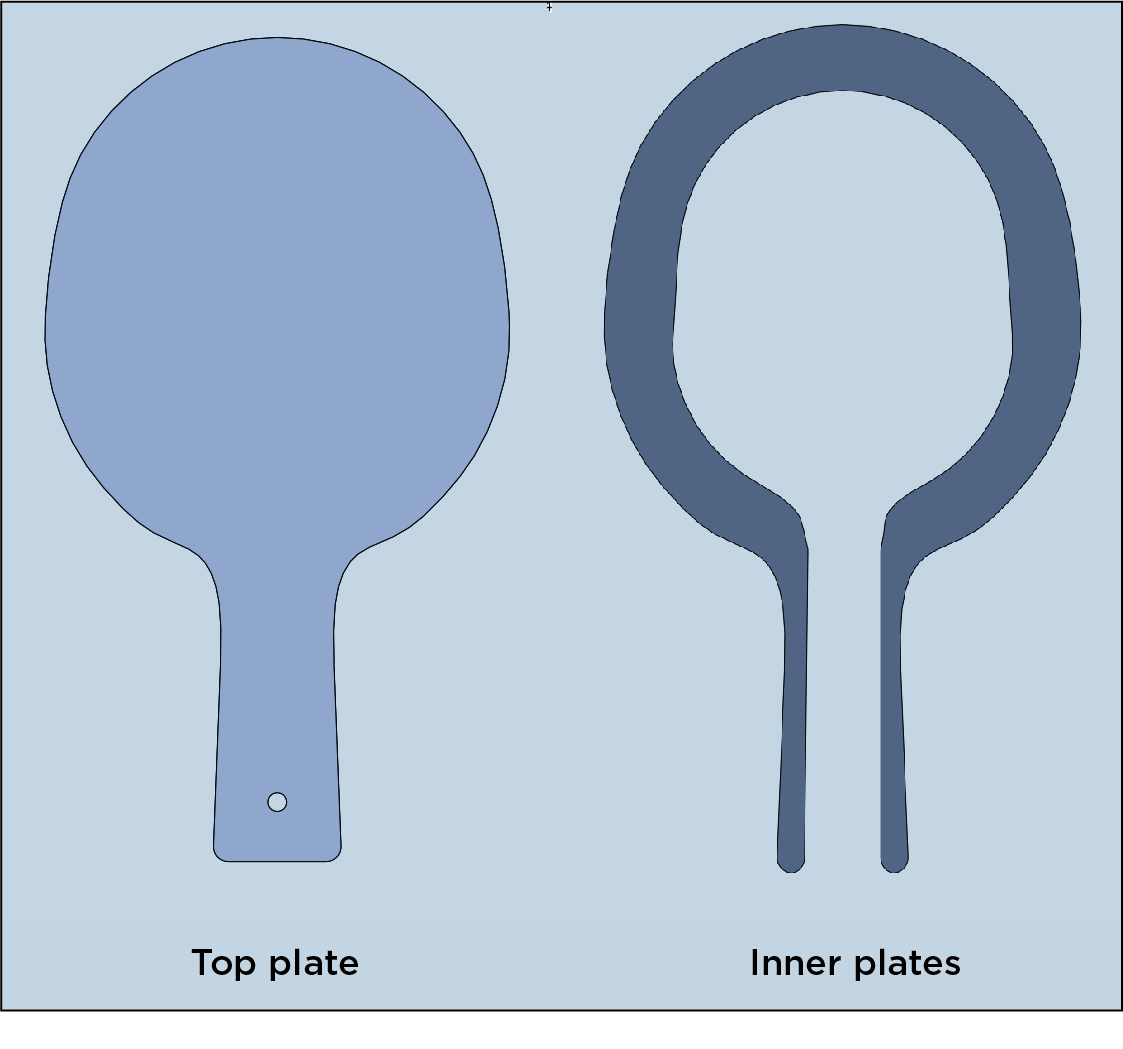
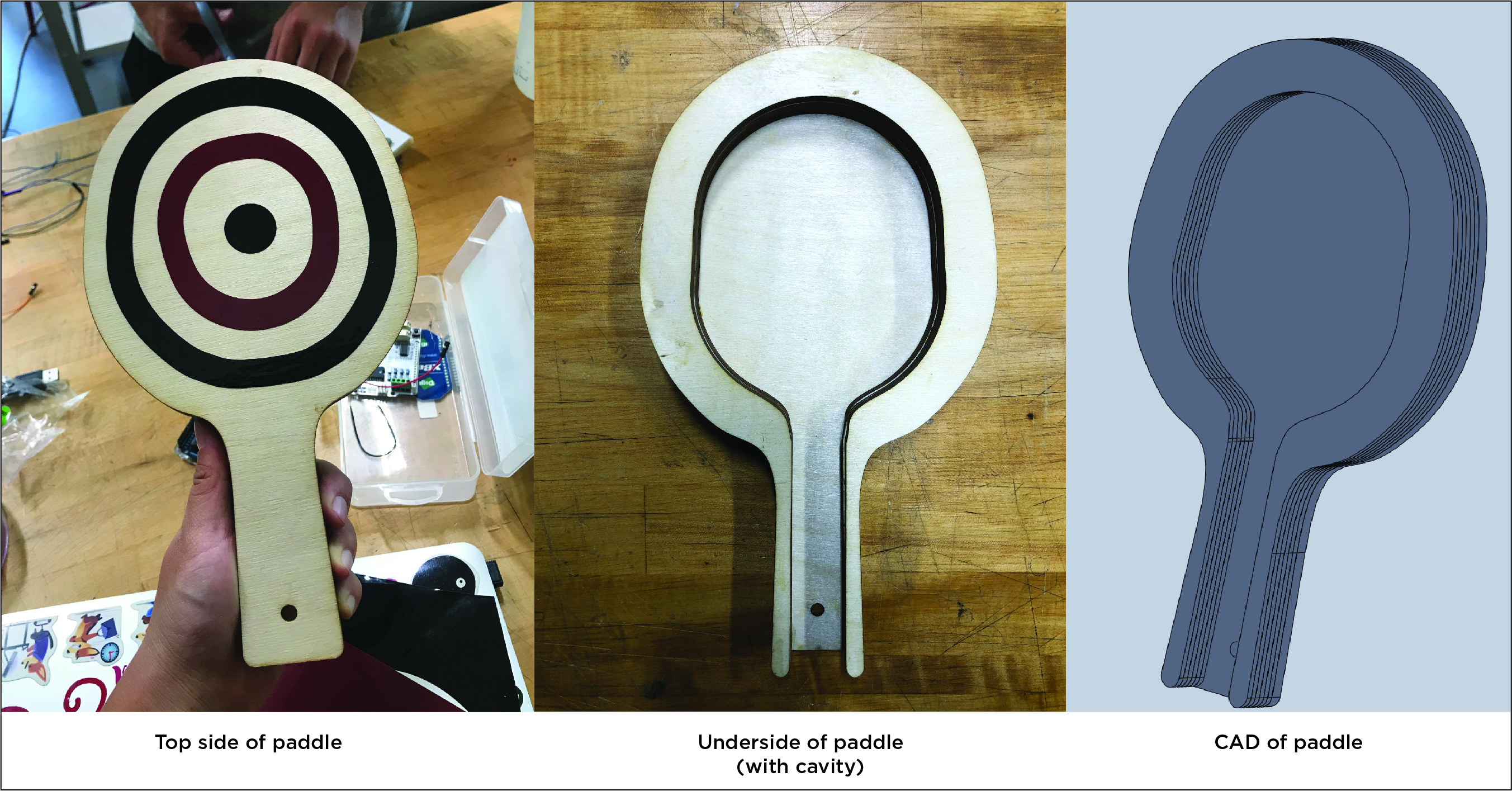
The paddle is made out of 9 pieces of wood glued together. We laser cut our base and 8 inner layers (which is essentially the base with an additional cutout) out of 1/8" plywood and glued them together. We also made vinyl cut stickers to mimic the pattern of an actual paddle ball. The cavity in the paddle creates space for us to place all our other electronic components within the paddle. The hole through the handle of the paddle is present for us to put the motors directly beneath the user's hand, and to also run the USB cable into the paddle. Since we do not have a base for our paddle, we used athletic tape to wrap the handle. We chose this intentionally so that the motors will be directly beneath the user's hand, and there is no other material that will damp the vibrations that the user will feel. The athletic tape also adds the additional tactile effect of what users would actually feel if they were to hold a real paddle, which has a tape-like grip as well.
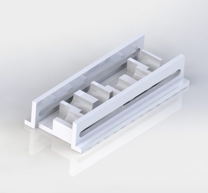
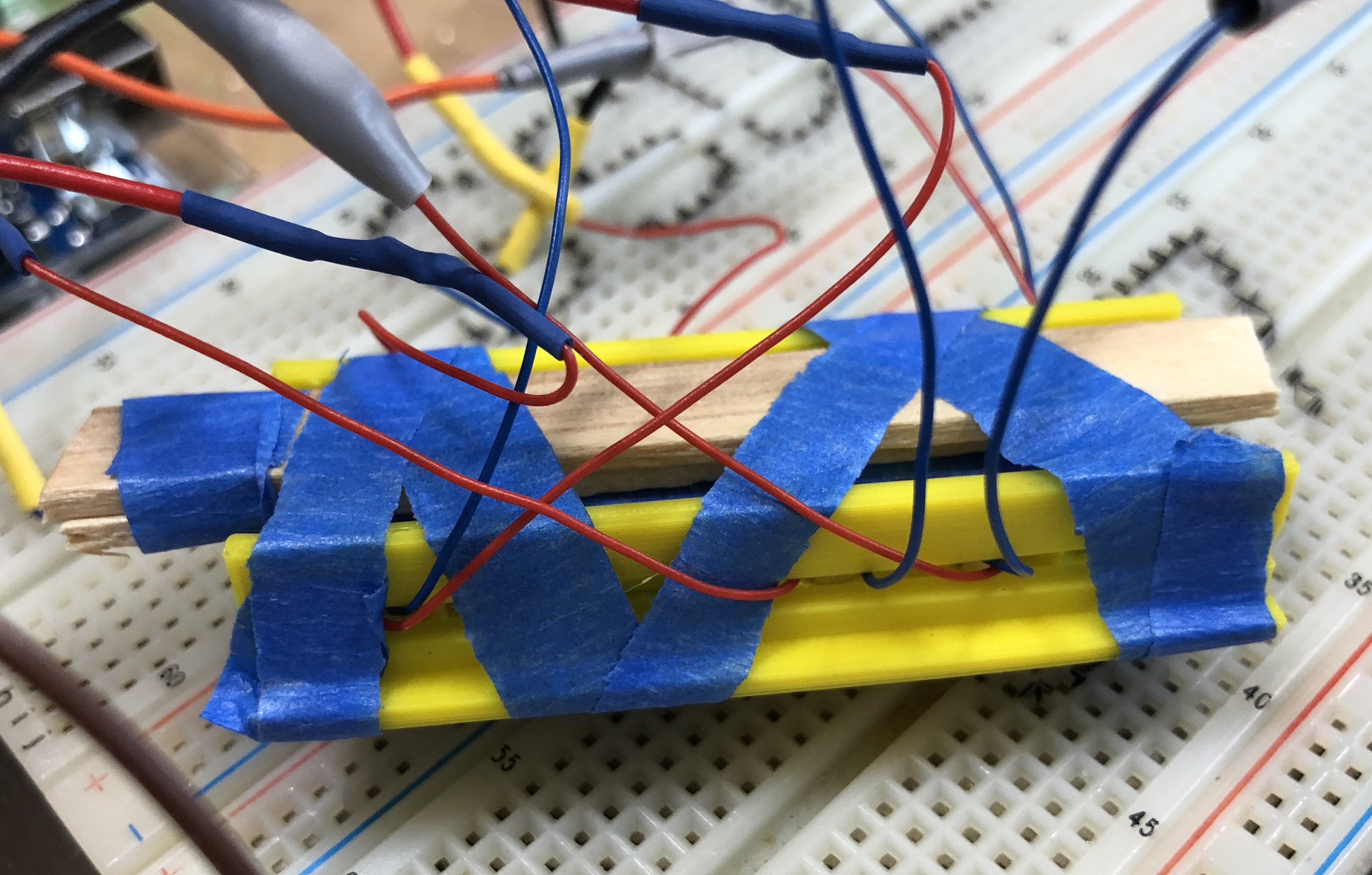
In order to house our motors (more in next section under electronic hardware components), we built a housing that was printed from a 3D printer. The housing is able to hold 6 motors. We used tape and popsicle sticks to hold the motors down in place in the housing.
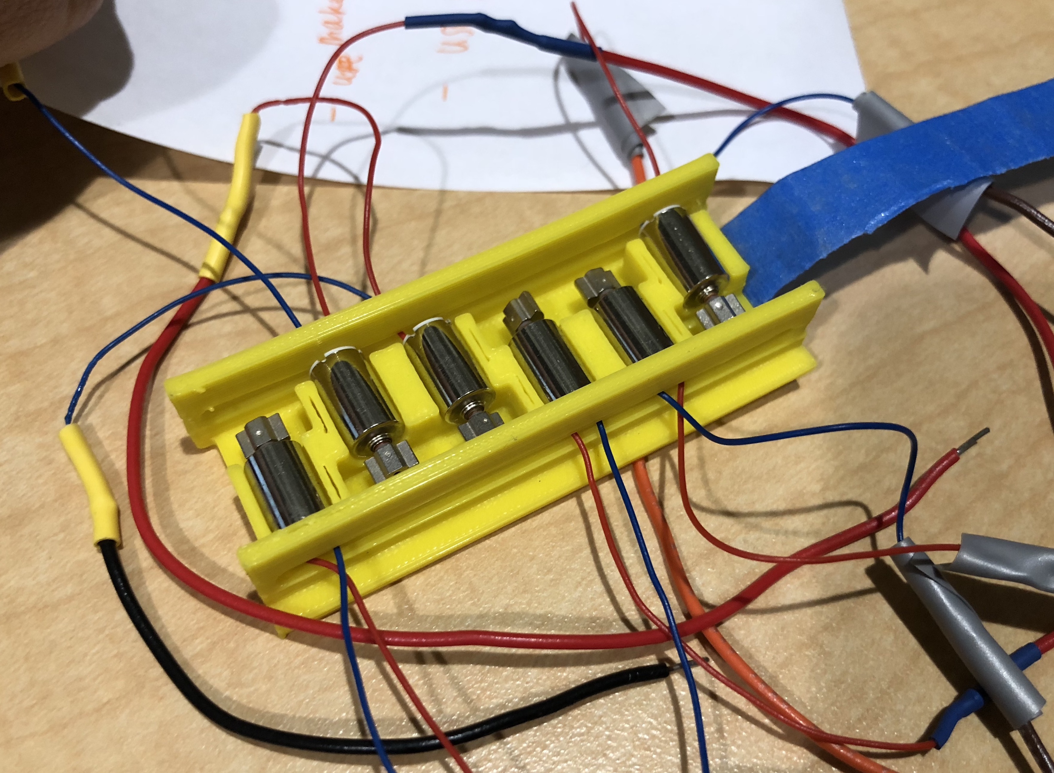
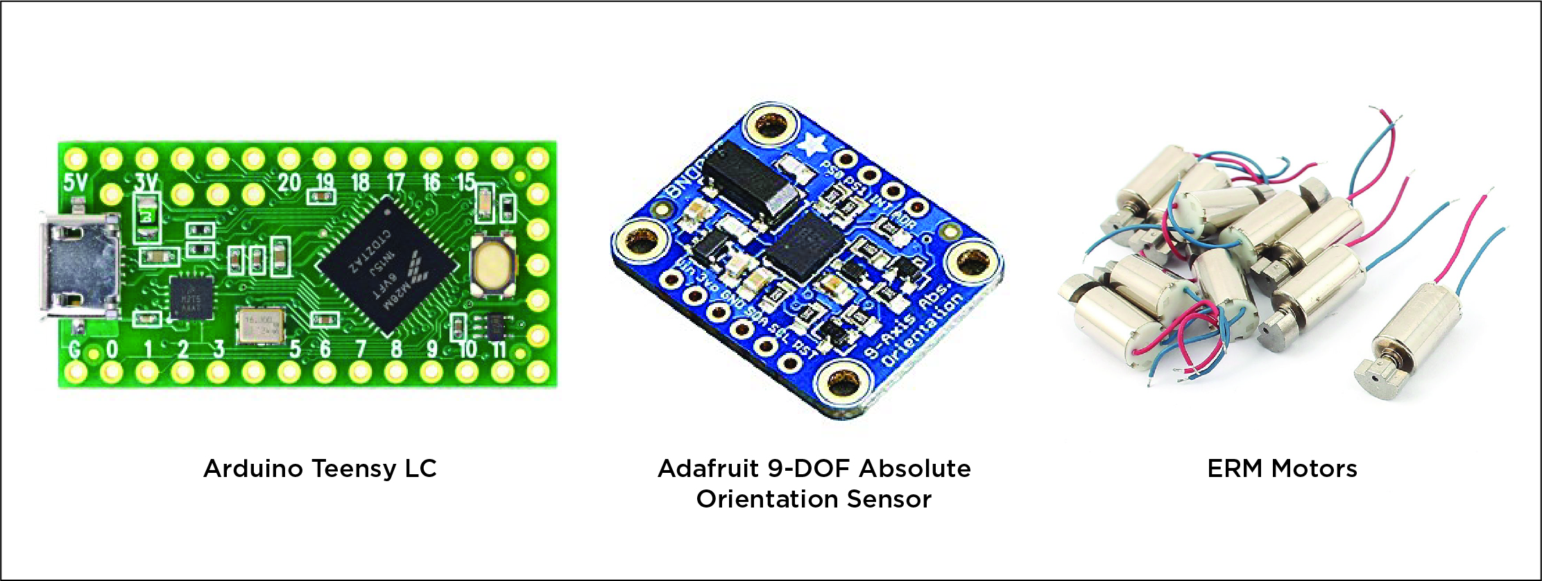
The chief electronic hardware components of this device were the Arduino Teensy LC microcontroller, Adafruit 9-DOF Absolute Orientation Sensor (BNO055) (this is the IMU), and six 8000rpm ERM motors. The various components are shown below. Additional components included wires, solder and the breadboard that the various components were mounted on.
This is the wiring schematic of our electronic hardware components.
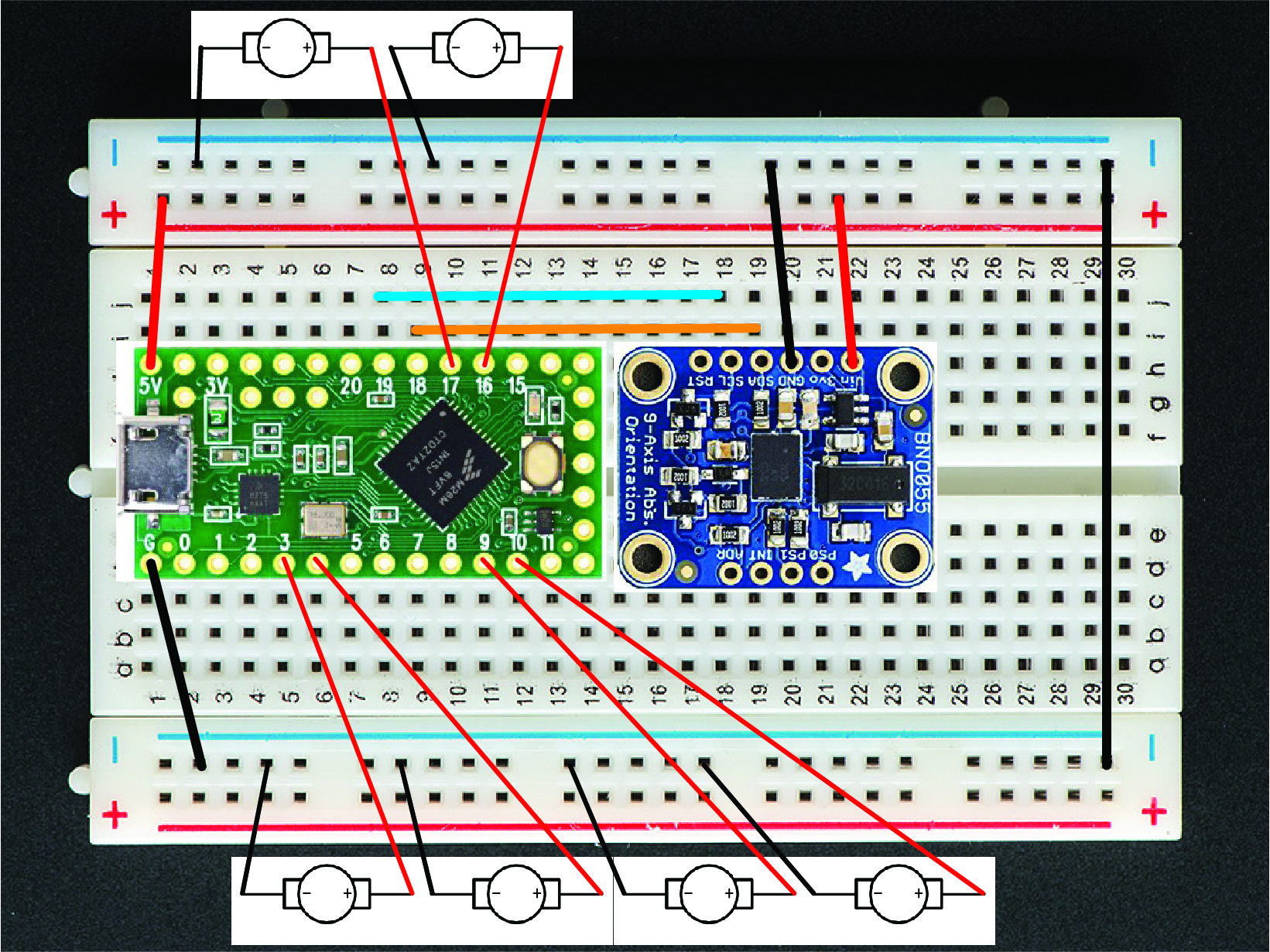
Here are the steps to assemble our circuit:
1. SDA pin on the IMU goes to pin 18 (A4) on the Teensy LC
2. SCL pin on the IMU goes to pin 19 (A5) on the Teensy LC
3. Connect the Vin on the IMU to the power rail, which is connected to the 5V output of the Teensy LC
4. Connect the positive ends of the motor to PWM outputs of the Teensy LC. We choose to use Pins 3, 4, 9, 10, 16, 17. We decided to connect our 6 motors to separate PWM pins instead of connecting in series so that each motor would have maximum power and vibration.
5. Connect negative ends of the motor, GND of the Teensy LC and IMU to a common ground
Here's what our paddle looks like on the underside: 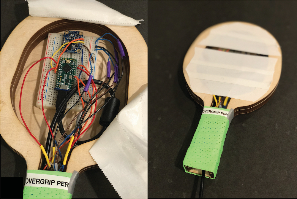 The breadboard is attached to the paddle using adhesives, and we also taped the underside to prevent any components from falling out.
System dynamics
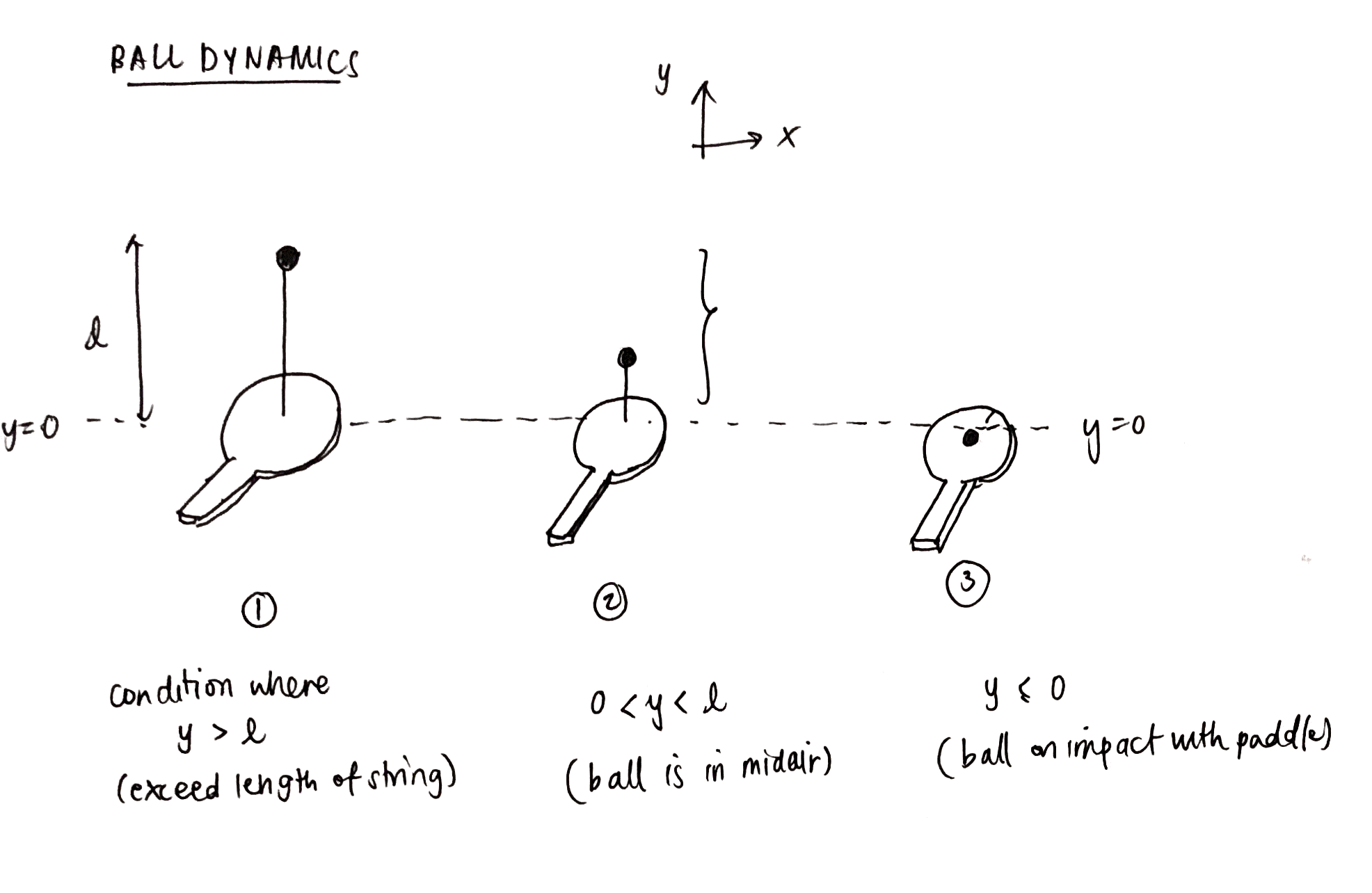
For our paddle ball dynamics, we broke down the bouncing ball into 3 main states, as seen in the above image.
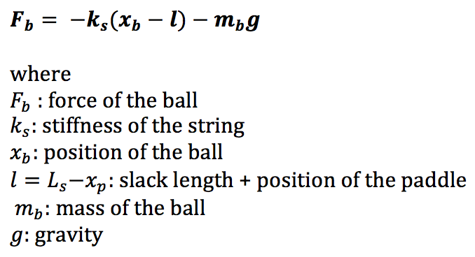
l = slack length + position of paddle
State 1: y ≥ l
This is the condition where the height of the ball exceeds the total height of the string and paddle position combined. Since the string is elastic, we can model the string as a spring with some stiffness, k. The dynamics of the ball in this state can be modeled as a spring-mass system, where the spring is pushing upwards on the ball, while the ball still experiences the downward force of gravity.
One of the haptic effects we rendered was the effect of changing the slack length. Slack length is the length of the string that the ball height must exceed before the ball experiences a spring force exerted by the string.
There are 3 conditions for the slack length:
(1) Normal slack length -- In our code, we set slack length = 20cm. The string is of a normal length, and the ball height needs to exceed 20cm before it feels the pull of the string back to the paddle. The ball dynamics is what we would expect to see in a normal game of paddle ball.
(2) No slack length -- In our code, we set slack length = 0. Because the length of the string is infinitesimally small, it is as if the string becomes a rubber band immediately and the ball will always have a spring force that pulls it back to the paddle. The ball will always want to bounce as close to the paddle as possible since the ball is essentially tethered to the paddle. In this case, we see that the ball will bounce back to the paddle faster than the ball in the other two string conditions.
(3) Infinite slack length -- In our code, we set slack length = 150m.The slack length is very long and the ball position will never exceed string length. This means that the ball bounces as if it is not restrained by the string, since there will be no spring force from the string that pulls the ball back to the paddle. We can assume that the string is "non-existent" since it has no effect on the ball. Gravity and the upward force of the paddle (by the user) are the only forces acting on the ball.
The terminology for infinite slack length and no slack length may be a little unintuitive at first, but watching the videos in the Demonstration section will help you better identify the differences in both these conditions. Both are extreme conditions that lie on opposite ends of the spectrum where changing string length affects the bouncing ball dynamics.
We plotted the effects of varying slack length to see how this affects the maximum height the ball can reach.
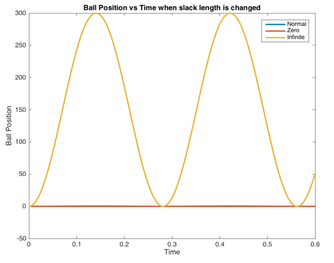
The above figure shows when all 3 conditions, (1) normal slack length, (2) no slack length, (3) infinite slack length, are plotted together. As we can see here, the ball in the infinite slack length condition has the largest maximum height. All the plots are plotted with the same acceleration and paddle position. Note that because we modeled this system as a spring-mass system without damping, the plots show oscillation without decay. Damping is added in the system but it will be covered later.
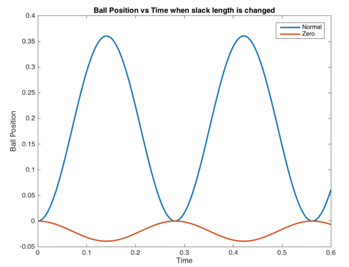
This figure is a close-up of the previous figure, to show the differences between (1) normal slack length and (2) no slack length.
Another haptic effect we rendered was the effect of changing the stiffness of the string.
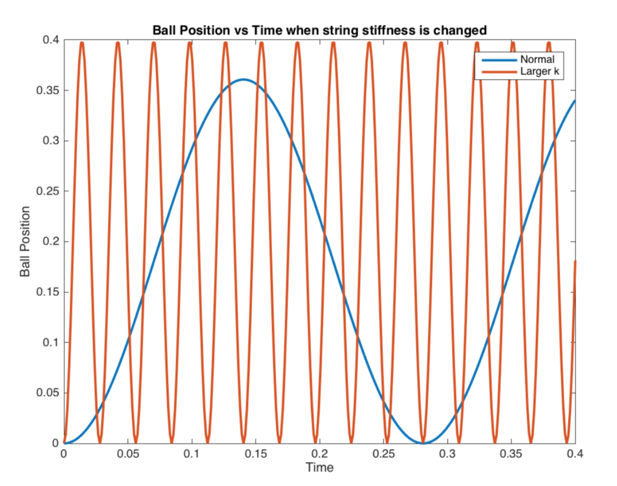
In this figure, we compare the effect when the string has a spring constant of k = 5N/m versus a string with greater stiffness, k = 500N/m. With increased stiffness, the ball will experience a larger "spring" force from the string because F = -kx. Due to a larger restoring force, the ball will get "pulled back" to the paddle with greater force. As seen in the above plot, the ball returns to its original position much faster when k is higher (i.e. period of one oscillation for a string with higher k is smaller).
State 2: 0 < y < l
This is the condition where the ball is midair. The ball is free falling due to gravity.
State 3: y ≤ 0
This is the condition where the ball collides with the paddle.
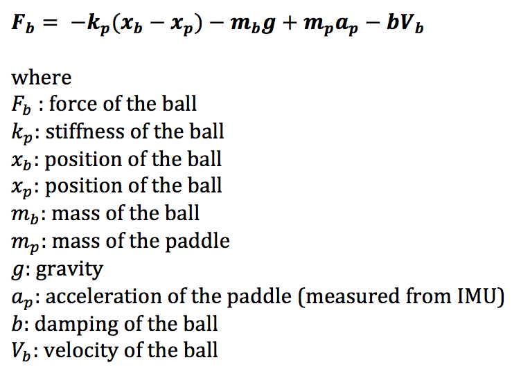
Based on literature [3], we decided to model our bouncing ball on impact with the paddle as a linear mass-spring-damper system. The main difference is that while the paper accounts for gravity as the only force acting on the ball, we have an additional upward force, which comes from the paddle, when the user hits the ball with the paddle. This gives rise to an additional F=mpap term.
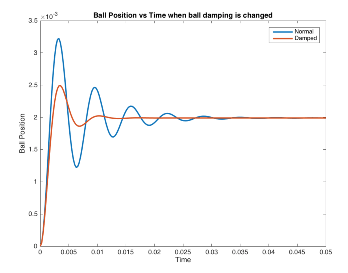
We decided to change the bounciness of the ball by adjusting its damping as another one of our haptic effects.
There are 2 conditions for the bounciness of the ball:
(1) Bouncy ball -- In our code, we set damping = 3Ns/m.
(2) Damped ball -- This ball has higher damping as compared to the bouncy ball, i.e. it will bounce less and not as high. In our code, we set damping = 8Ns/m.
The above figure shows the difference in oscillations when the there is a change in the ball's damping factor. As expected, the ball decays to steady state faster when it is more damped and it also has a smaller amplitude.
So what does the motion of the bouncing ball look like when we combine all three of these states?
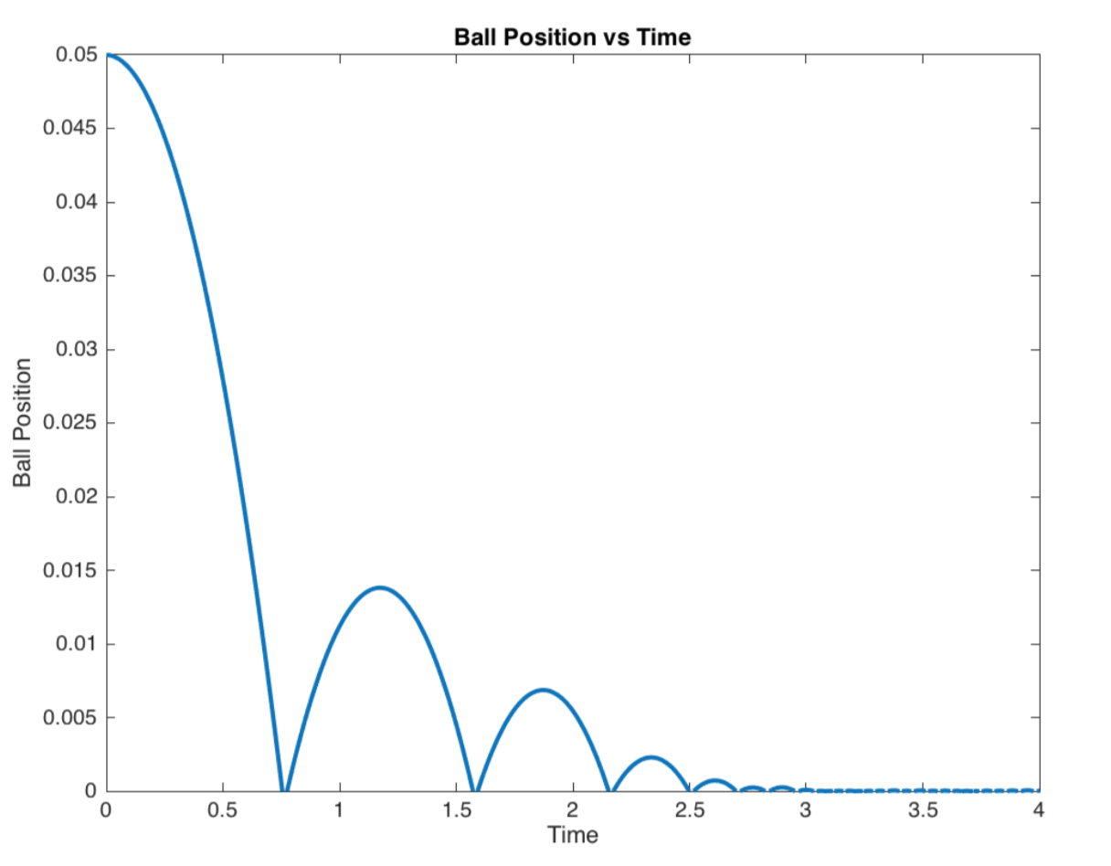
The above is a plot of the ball's bouncing motion as a function of time. This is assuming that acceleration of the paddle and position of the paddle is kept constant.
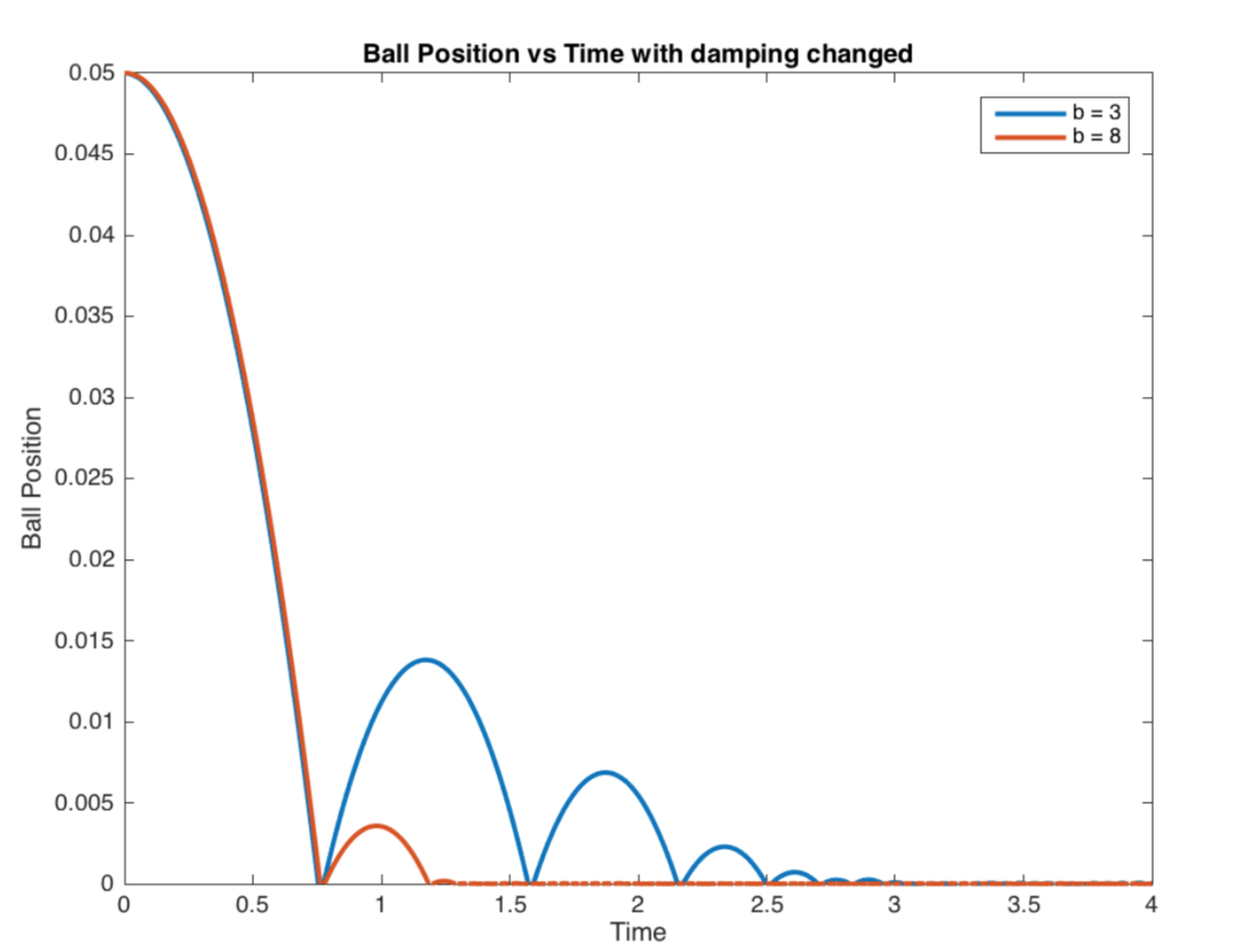
We also plotted the motion of a bouncy ball and a damped ball to show comparisons between these two conditions. As expected, the damped ball reaches 0 first and the height of its first bounce is much smaller than that of the bouncy ball.
Software
Arduino
We took the three states from the Dynamics section and implemented it into our Arduino code with the various boundary conditions. We also integrated some starter code from the IMU sensor tutorial online [8] to obtain the measurements from the built-in accelerometer and gyroscope for the paddle's acceleration and position. Since Haptic Paddle Ball is a 1-DOF device, we were only interested in our device's pitch measurements (y-direction).
For the motors, the PWM output values can be written from 0 to 255. After some testing, we figured that 150 is the minimum value needed to be output, in order for the users to feel a light vibration (equivalent to the ball gently bouncing on the motor). The maximum is 255. The only time when the user will feel a "force" on the paddle is when the ball impacts the paddle (state 3). We will then scale this force from the ball by a certain scaling factor, such that the maximum power will be 255. We chose our scaling factor as 8 after some testing.
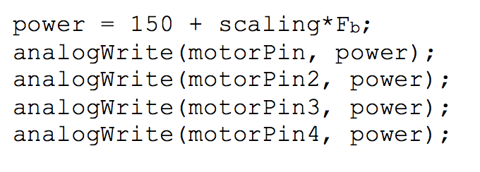
In other cases, the force on the paddle = 0 (when the ball is in the air), so the code will just be analogWrite(motorPin, 0);
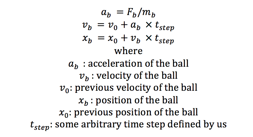
To find the position of the ball, we calculated the the acceleration of the ball, ab, after dividing the force of the ball, Fb by its mass. We integrate acceleration twice to find the ball's position.
In order to render proper graphics in Processing, we called the the Serial.println() command to output both the position of the ball and paddle. The position of the ball is calculated above, and the position of the paddle is measured by the gyroscope in the IMU.
Processing
To render the graphics of our paddle and ball in Processing, we first downloaded a paddle as a 3D object and imported it (the link to download the file can be found in the Files section). We also modified some Processing code from the IMU sensor tutorial [8] so that our paddle in Processing would move when we were moving the IMU sensor.
We rendered our ball as a sphere and mapped the movement of the ball to the ball position that was output from Arduino. We also added a string, to mimic the actual paddle ball game, with one end connected to the paddle and the other end connected to the ball.
Demonstration / application
To showcase the educational aspect of Haptic Paddle Ball, we created several different haptic effects for users to explore. The simulations consisted of balls with different damping, strings of different lengths, and different stiffness for the string.
The following are videos of Haptic Paddle Ball in action, simulated under various conditions:
Bouncy Ball Conditions
(1) Bouncy Ball + Normal Slack Condition https://www.youtube.com/watch?v=i_aLBql4Ufo
(2) Bouncy Ball + Infinite Slack Condition https://www.youtube.com/watch?v=13q04Bi3L_o
(3) Bouncy Ball + No Slack Condition https://www.youtube.com/watch?v=eoBI2wLPP2s
(4) Bouncy Ball + Stiff Slack Condition https://www.youtube.com/watch?v=lrYs0ITVCKU
Damped Ball Conditions
(5) Damped Ball + Normal Slack Condition https://www.youtube.com/watch?v=DQNbGUC_SUM
(6) Damped Ball + Infinite Slack Condition https://www.youtube.com/watch?v=uEX--992ijE
(7) Damped Ball + No Slack Condition https://www.youtube.com/watch?v=g9M-j3ibHmg
(8) Damped Ball + Stiff Slack Condition https://www.youtube.com/watch?v=yr0cTCcUL5E
Results
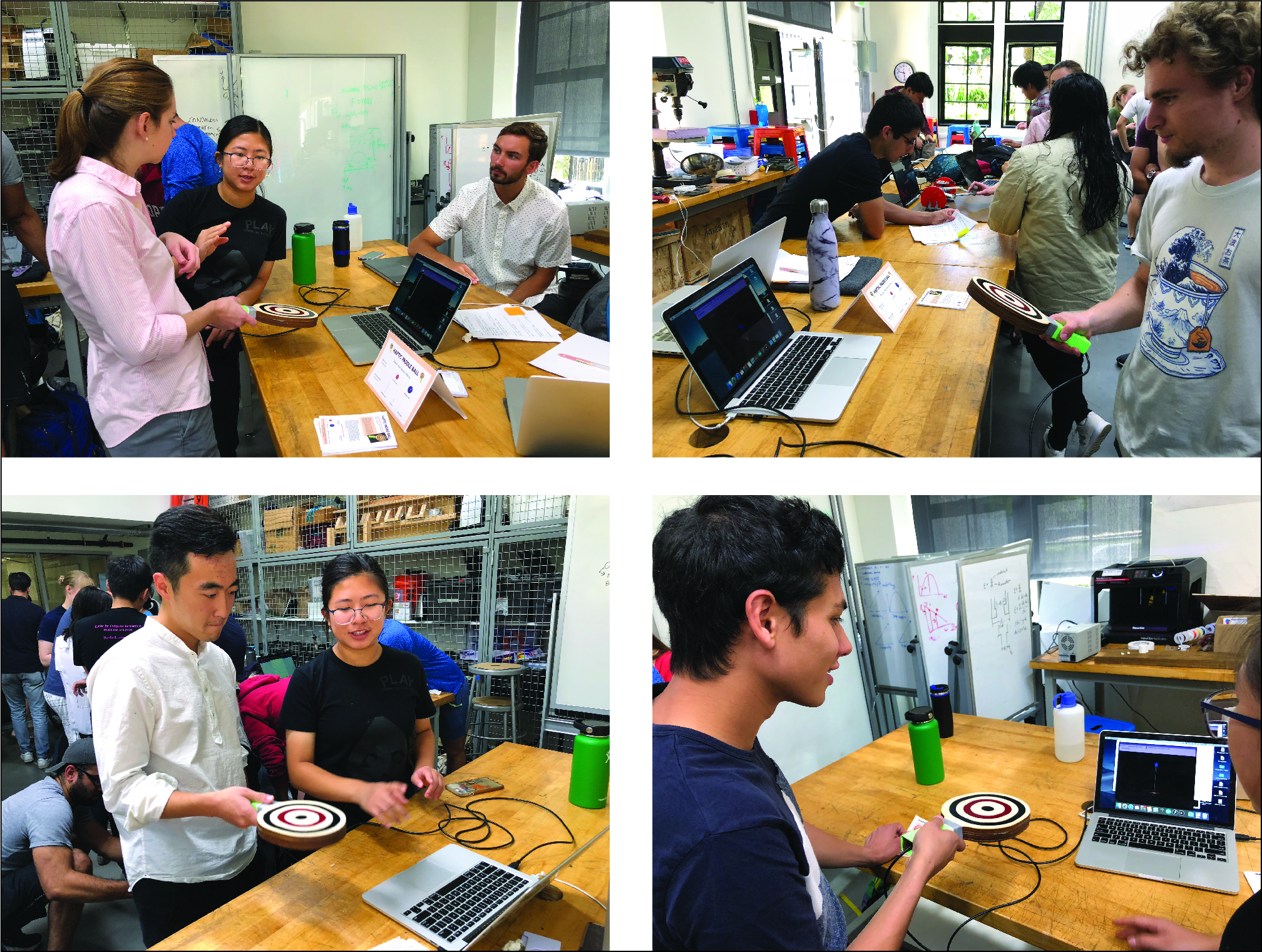
Haptic Paddle Ball was demonstrated at the ME327 open house with 30+ visitors. Visitors who interacted with our device gave largely positive feedback and opinions. They really liked the device because it felt satisfying and the graphics sold it for them. Additionally, several people also commented that they preferred our Haptic Paddle Ball over the original paddle ball game because the ball never falls off the paddle and it makes them feel like they are always winning (a wonderful confidence booster!). One person even said that Haptic Paddle Ball was perfect.
Though we wish that Haptic Paddle Ball was perfect, and we talked about future iterations in a later section, we were very satisfied with our device and responses from our users. The entire system felt smooth and Haptic Paddle ball functioned as expected as it provided a compelling simulation of the actual paddle ball. The visual feedback from processing definitely played a big part in tying the user's experience together as well. The only downside of our paddle was that it took some time to load up the various haptic effects into the paddle, so users had to wait for awhile in order to try the various ball and slack length conditions.
We made some interesting observations from people interacting with Haptic Paddle Ball. For instance, some users found it easier to bounce the ball in the bouncy ball than the damped ball condition, and users were also able to differentiate the dynamics of the balls in both these conditions, assuming all other variables remain constant. Users had to spend some time figuring out how the ball bounces and moves, but once they got the hang of it, they were able to bounce it at or close to resonant frequency, which was similar to what we read in literature [5]. At the same time, users also "hit" the ball with very little force initially, so they only saw the ball bounce a short distance. We needed to explain that they could provide a larger force/acceleration to the paddle to make the ball move further. Some comments we received were that the strength of the vibrations from the motor could be better. For instance, the graphics showed the ball bouncing with different amounts of force, but some users found it harder to distinguish the different vibration intensities in the paddle they were holding. Others also asked about additional DOFs and tried to rotate our paddle to see if it affected ball movement in any way. We addressed some of these comments in the next section.
Future Work
Future Iterations
1) Integrate our Haptic Paddle Ball with bluetooth modules. This will make our handheld paddle wireless and the paddle will not be constrained in movement by the USB cable connecting the Arduino to the computer. Making the paddle wireless and handheld will make it even more similar to an actual paddle ball game, and improve the user's perception of our device.
2) Incorporate additional degrees of freedom into Haptic Paddle Ball. At the moment, Haptic Paddle Ball only has 1-DOF in the y direction, i.e. both the ball and paddle will only move in the y direction, as seen in our graphics. If users were to currently tilt the paddle in the x and z directions, the graphics on our computer will remain the same. This could cause some inconsistencies between the actual device movement and perceived graphic movement by the user.
3) Adjust the sounds of the motor such that it actually sounds like a bouncing ball. Currently when the paddle hits the ball or when the ball impacts the paddle, we hear the whirring due to the vibration of the motor. If we are able to play the sound of a bouncing ball, this will make the perception of the paddle ball game more realistic.
4) Test Haptic Paddle Ball in an educational environment to determine how useful it is to teach students about spring constants and damping concepts.
5) Instead of having 3D graphics on our computer screen, we could potentially implement our graphics with AR/VR instead to make the rendering more realistic.
6) We could set up 2 paddles simultaneously for users so that they could compare between the conditions. Currently, it takes some time to upload the various haptic effects to the Arduino and so comparing between the haptic effects involves a memory aspect, which may not be ideal. Our system was also a little unreliable at times and aim to rectify this.
Future Applications
1) Haptic Paddle Ball can be used in classrooms to help students develop a better intuition and understanding of how a ball will bounce differently when its parameters, such as the stiffness of the string and damping, are changed.
2) Haptic Paddle Ball can replace the actual paddle ball and be used as a fun game to relieve boredom as well as a good tool to help people practice before transitioning to the real paddle ball game.
3) Since the linear mass-spring-daming model is a commonly used model that was implemented in this device, our haptic device may inform the design of future haptic devices, which could use a similar model, that are not limited to educational purposes only. Alternatively, our Haptic Paddle Ball model can be used to model other handheld games.
Acknowledgments
We would like to thank Professor Allison Okamura, Cara Nunez and Julie Walker for their teaching, guidance and support in our paddle system. We would also like to thank the CHARM Lab for lending us various components that were crucial for our paddle system.
Files
- Attach:PaddleArduinoCode.zip
- Attach:PaddleProcessingCode.zip
- Attach:Paddle_costs.pdf
- Attach:MotorHousing.zip
- Attach:PaddleDesign.zip
- Attach:Paddle3Dobject.zip
Note that other components that were used in our system are the (1) Adafruit BNO055 Absolute Orientation Sensor (IMU), (2) Teensy LC, (3) Breadboard and wires. We already owned most of the components and borrowed the IMU from the CHARM Lab. The ping pong paddle that was rendered in Processing, which we attached on this site as the Paddle3Dobject.zip file, is downloaded from this site: https://free3d.com/3d-model/pingpong-paddle-v1--337871.html
References
[1] H. Culbertson, S. Schorr, and A. Okamura. Haptics: The Present and Future of Artificial Touch Sensation. Annual Review of Control, Robotics, and Autonomous Systems, Vol. 1:385-409 2018 https://www.annualreviews.org/doi/full/10.1146/annurev-control-060117-105043
[2] K. E. MacLean, M. J. Shaver and D. K. Pai, "Handheld haptics: a USB media controller with force sensing," Proceedings 10th Symposium on Haptic Interfaces for Virtual Environment and Teleoperator Systems. HAPTICS 2002, Orlando, FL, USA, 2002, pp. 311-318. https://ieeexplore.ieee.org/document/998974
[3] M. Nagurka and Shuguang Huang, "A mass-spring-damper model of a bouncing ball," Proceedings of the 2004 American Control Conference, Boston, MA, USA, 2004, pp. 499-504 vol.1. https://ieeexplore.ieee.org/document/1383652
[4] de Rugy, Aymar, et al. "Actively tracking ‘passive’ stability in a ball bouncing task." Brain research 982.1 (2003): 64-78. https://www.sciencedirect.com/science/article/pii/S0006899303029767
[5] C. J. Hasson, N. Hogan and D. Sternad, "Human control of dynamically complex objects," 2012 4th IEEE RAS & EMBS International Conference on Biomedical Robotics and Biomechatronics (BioRob), Rome, 2012, pp. 1235-1240. https://ieeexplore.ieee.org/document/6290911
[6] Han, Insook, and John B. Black. "Incorporating haptic feedback in simulation for learning physics." Computers & Education 57.4 (2011): 2281-2290. https://www.sciencedirect.com/science/article/pii/S0360131511001412
[7] Williams II, Robert L., Meng-Yun Chen, and Jeffery M. Seaton. "Haptics-augmented high school physics tutorials." International Journal of Virtual Reality 5.1 (2002): 1-12. http://citeseerx.ist.psu.edu/viewdoc/download?doi=10.1.1.129.6925&rep=rep1&type=pdf
[8] Townsend, Kevin. “Adafruit BNO055 Absolute Orientation Sensor.” Overview | Adafruit BNO055 Absolute Orientation Sensor | Adafruit Learning System, 10 May 2019, https://learn.adafruit.com/adafruit-bno055-absolute-orientation-sensor?view=all
Appendix: Project Checkpoints
Checkpoint 1
Goal 1: Complete Mechanical Design & Assembly
CAD assembly of our paddle:
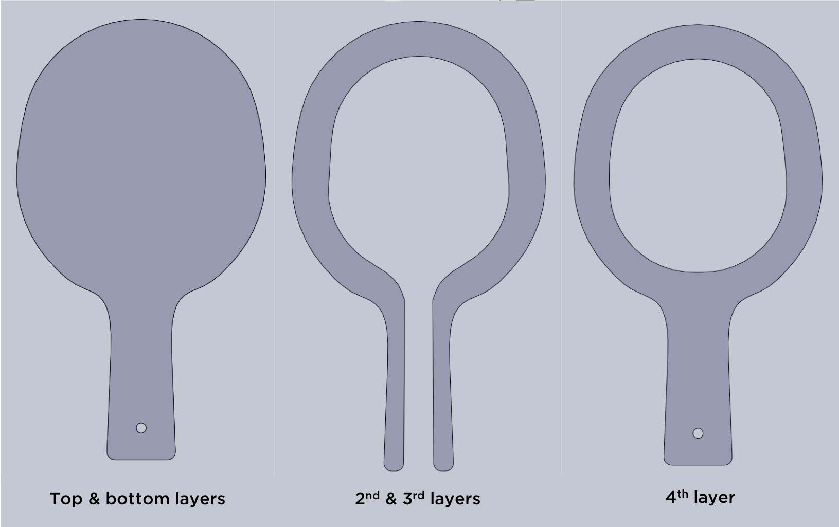
Figure 1: Individual layers of the Paddle

Figure 2: Various views of the CAD model of the Paddle
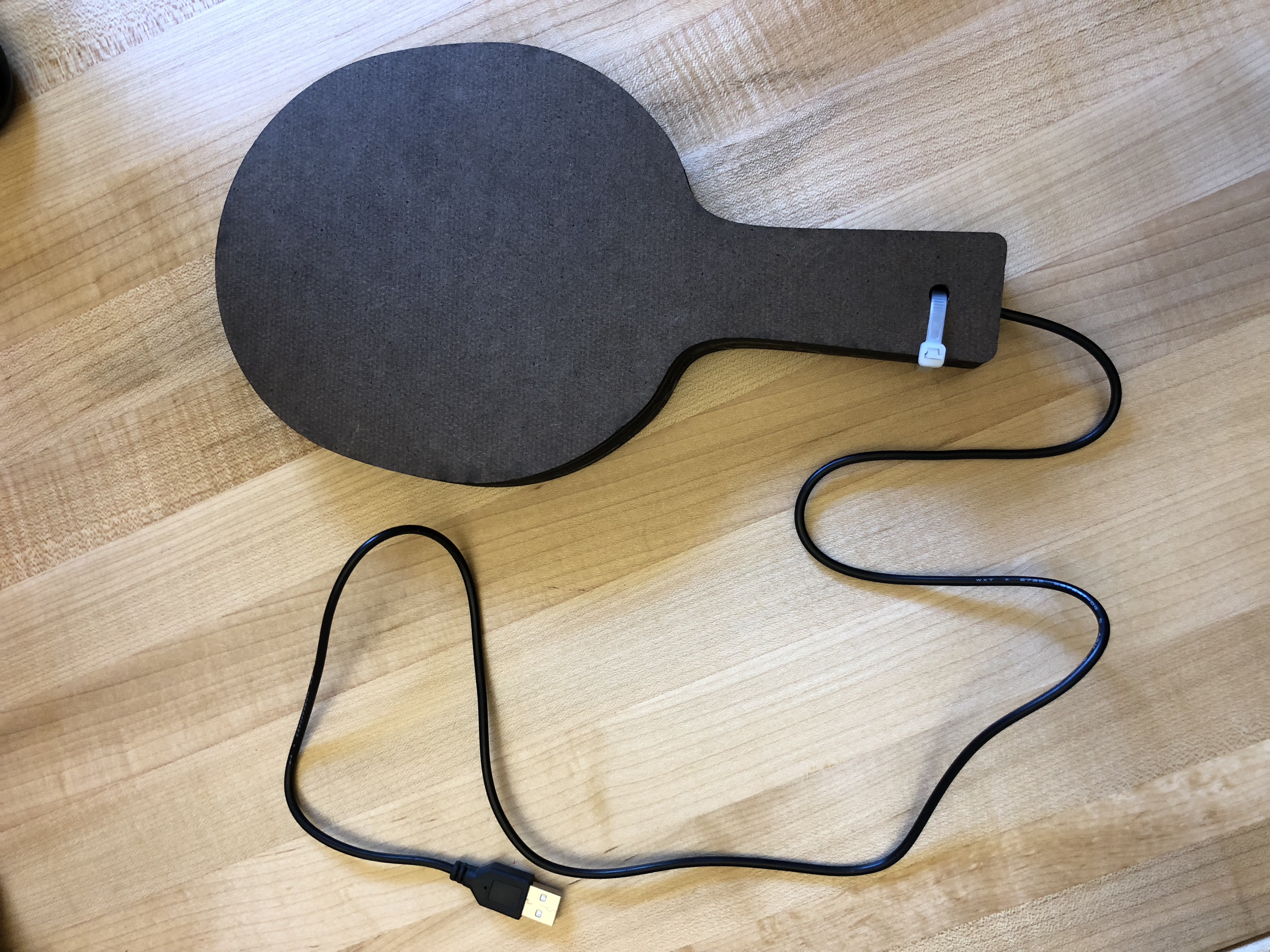
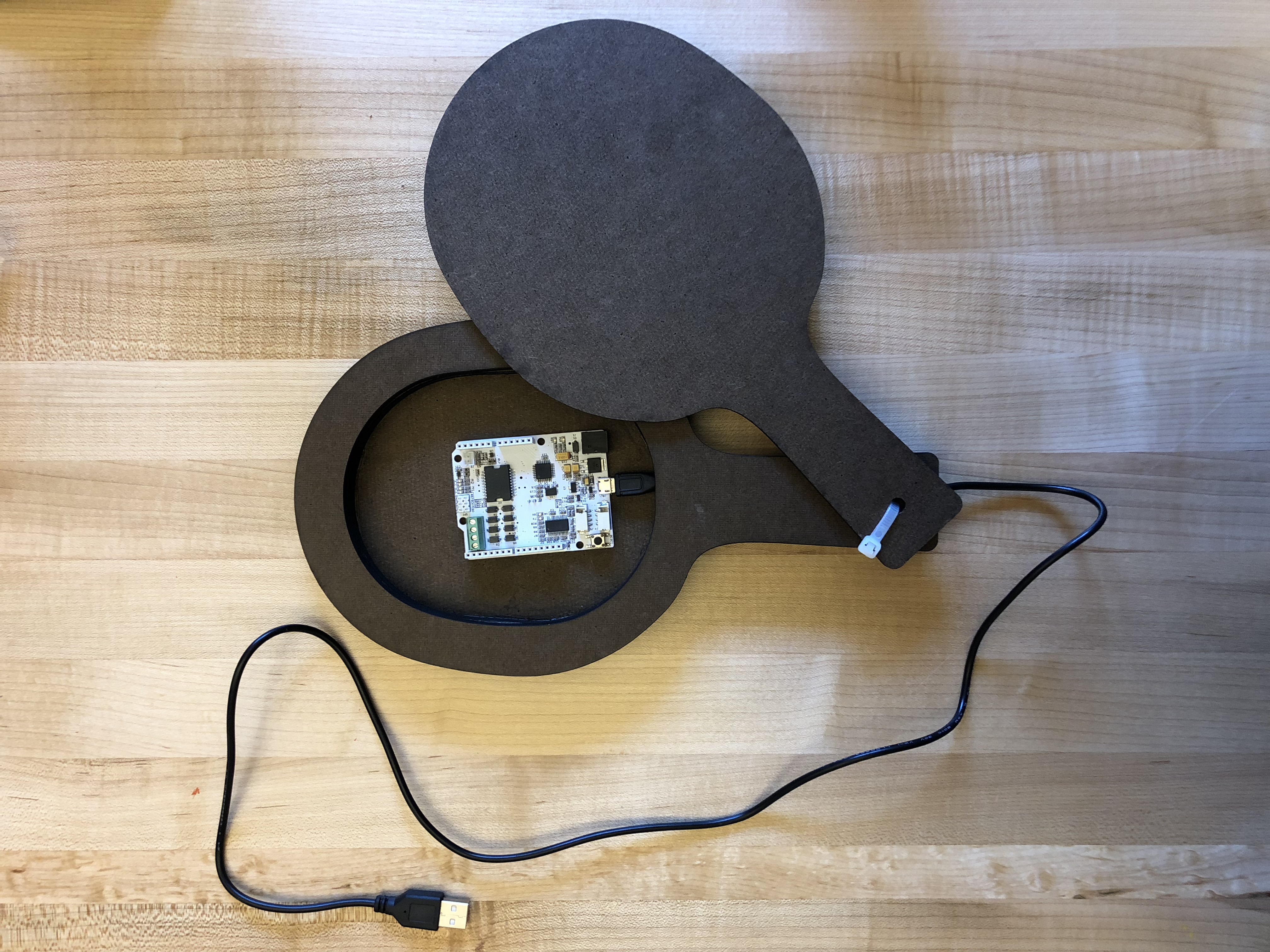
Figure 3: Prototype Paddle cut from Duron. (Note: the Hapkit board inside the paddle isn't our set up. We are showing the available space within the cavity)
Our paddle is made of five separate layers. We laser cut each layer of the paddle out of 1/4" thick Duron glued 4 of the layers together with wood glue. We left the top layer as a floating piece, which we attached with a zip-tie through a hole at the bottom, (we will be changing the zip-tie to a bolt) so that we can slide the top piece open to reveal a cavity, where we would store all our other components (motor, Arduino, IMU sensor).
Goal 2: Complete Electrical Circuit Assembly
We initially wanted to create a handheld haptic paddle and experimented with Bluetooth devices. However, we spent an entire day trying to figure out how to use the XBee modules but ran into a lot of difficulties, including setting up the wireless modules and interfacing the modules with an Arduino. We decided to revert back to non-handheld paddle, i.e. the paddle will be connected to our computer. We are still very interested in making the handheld device work, and it will be our stretch goal should time permit.
Not implementing the Bluetooth has eliminated the need for both a battery and bulky Bluetooth sensor. Without these, the electrical assembly of this device is relatively straightforward. Working off of an Arduino Teensy, we will connect an IMU to measure the relative angle of the paddle and linear acceleration and feed back this information to our microcontroller. Considering that thickness of our Paddle, we want to make sure that the user will be able to feel a haptic vibration that feels realistic enough. We are currently testing between two types of 3V vibrating motors with relatively high rpms, and exploring whether a single motor vs a system of motors would make the most sense. The motors will provide a haptic vibration to the user dependent on the linear acceleration of the paddle relative to the velocity of the ball.
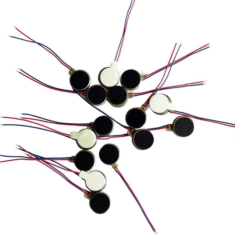
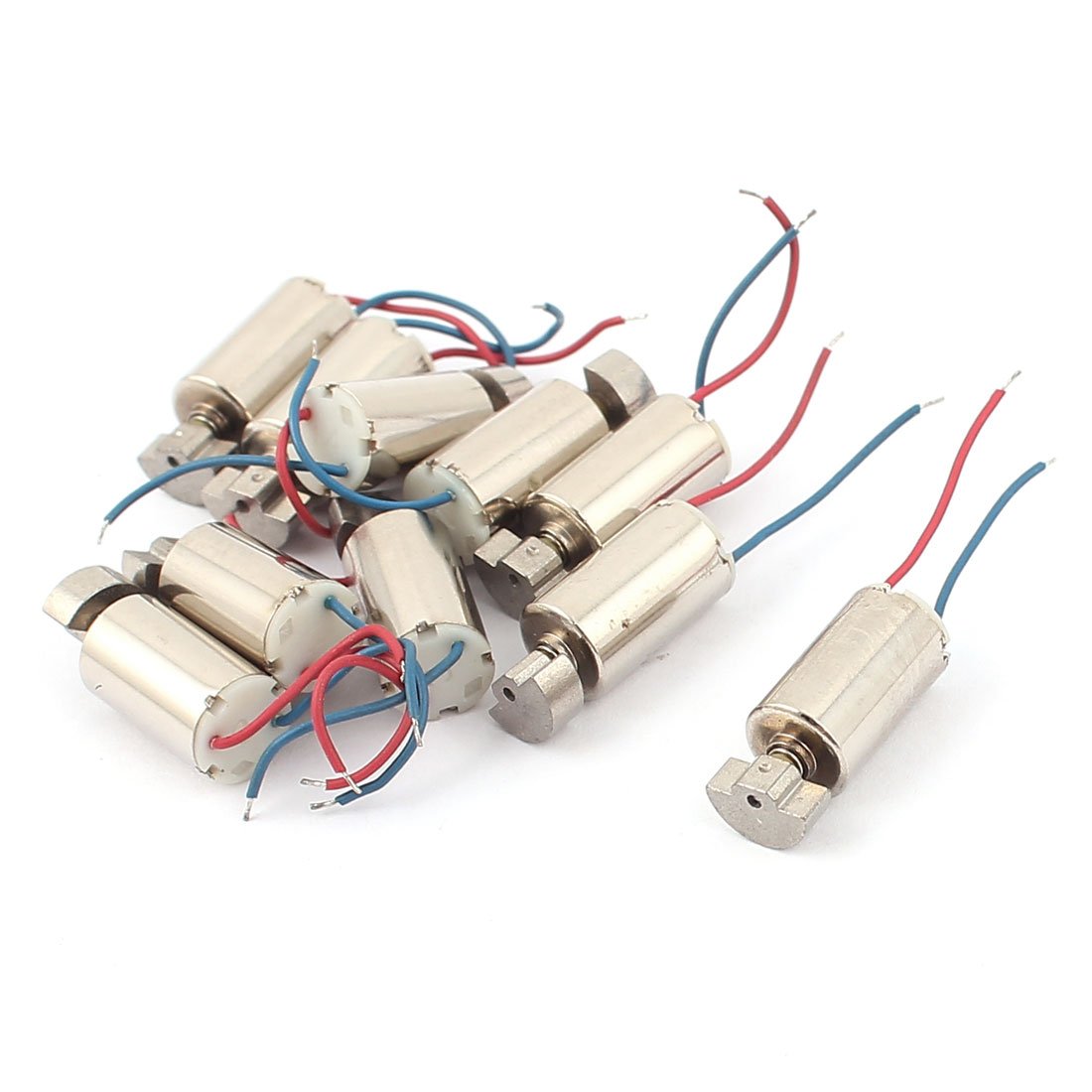
Figure 4: We are deciding between coin cell shaped vibrating motors (left) and ERM motors (right)
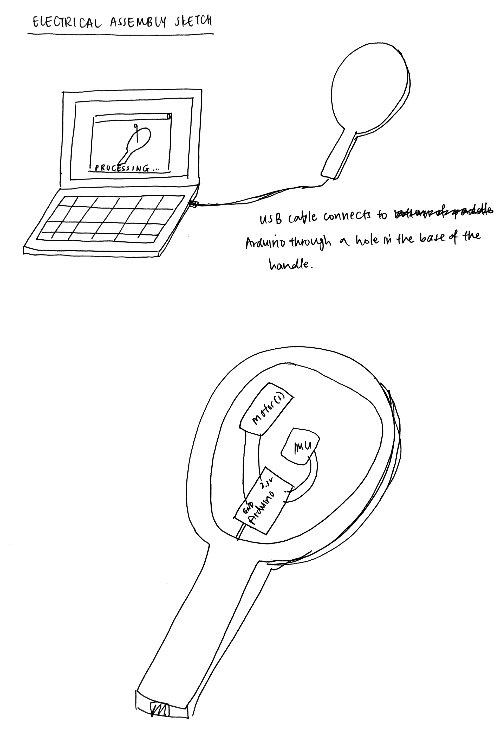

'Figure 5: Our circuit
Goal 3: Preliminary calculations for Paddle Ball Dynamics

We starting looking into modelling the dynamics of the paddle ball.

Figure 6: Paddle ball's three states
We are breaking down the dynamics of the ball into 3 distinct states:
State 1: y ≥ l
The string that is "attached" to the ball on one end and to the paddle on the other is elastic, and has length, l. As a result, when the height of the ball exceeds the length of the string, we can model the string as a spring with some constant, k (to be determined). Therefore, the dynamics of the ball can be modeled as a spring-mass system, where the spring is pushing upwards on the ball, while the ball still experiences the downward force of gravity. Since the string is connected to the paddle on the other end, the user will experience a force as well. F = kx-mg.
State 2: 0 < y < l
This is the condition where the ball is midair. Since the ball is free falling due to gravity, the force felt by the user, F = 0.
State 3: y ≤ 0
This is the condition where the ball collides with the paddle. Based on the paper we read by M. Nagurka and Shuguang Huang, "A mass-spring-damper model of a bouncing ball," (https://ieeexplore.ieee.org/document/1383652), we decided to model the ball as a mass-spring-damper system. The main difference from the paper is that while the paper only has gravity acting on the ball, we have an upward force from the paddle to hit the ball upwards, and there will be an additional F = ma term, where a is the term of acceleration of the paddle. (In this case, we are assuming that the ball and the paddle have the same mass, m).
my'' + by' + ky = ma - mg
Integrating the above equation gives us:
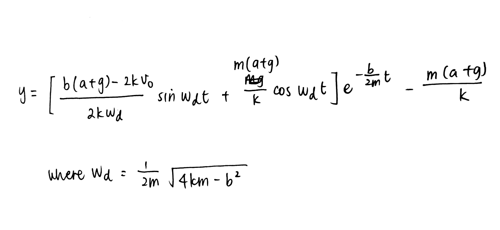
This equation gives us the motion of the ball during contact with the paddle.
The same paper also has similar equations that we can adapt, assuming the user no longer hits the ball with the paddle and the ball will simply bounce on the paddle. We are able to model the time between bounces and the max height that the bounce will reach, and this will be seen on Processing.
We are also planning on adding additional "conditions" where participants can play paddle ball but experience difference dynamic effects on the paddle (e.g playing paddle ball on another planet so gravity feels different, or assuming that collisions between the ball and the paddle are not fully elastic).
Goal 4: Preliminary code for Arduino and Processing
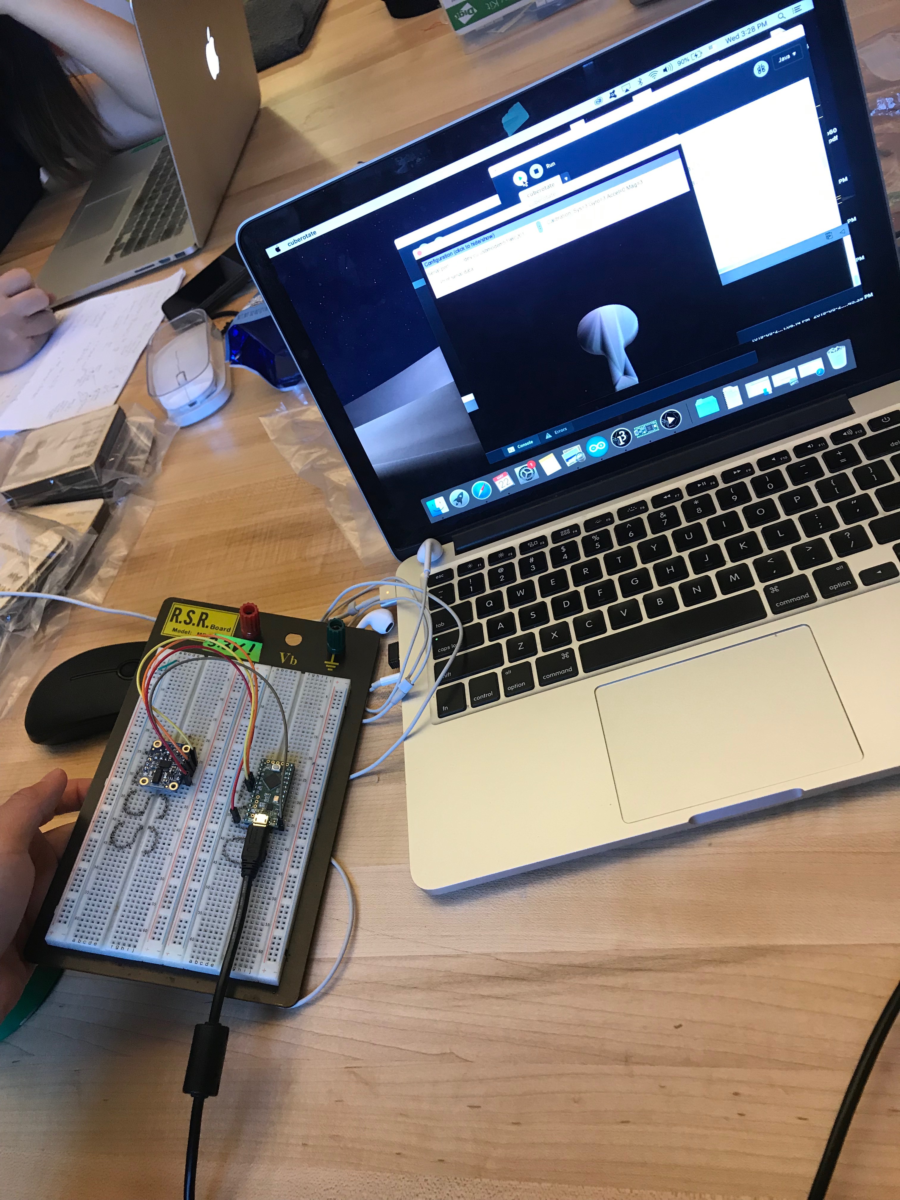
Figure 7: Playing around with the IMU and corresponding graphic in Processing
We are using the Adafruit 9-DOF Absolute Orientation (BNO055) to track the paddle's orientation. We used a Teensy LC micro controller to power it, and we plan on using this Teensy when hooking up the other motors, but we may change to an Arduino Uno in case we need more PWM pins to control the motors. We wanted to model this in 3D in Processing, so that the user is able to easily and quickly visualize the system that we are mimicking. Using this tutorial https://learn.adafruit.com/adafruit-bno055-absolute-orientation-sensor/arduino-code we were able to model the IMU's orientation with our CAD model of the paddle (which we exported as an obj file and put into Processing). so that when we moved the IMU, the paddle on screen moved along with it.
The Arduino code essentially outputs the IMU's x, y, and z orientation to Serial. Processing then computes the degrees of orientation using these values, and scales and draws the object imported based on the degrees (which is calculated within a loop, so that it moves at (almost) real time). Our next steps are to constrain the degrees of freedom of our visual console and to incorporate the ball/string into the visuals.
Additionally, the IMU has an accelerometer, which we'll be helpful for our dynamics calculations (ie F_user = m*a). Since we only care about the acceleration in the z-direction, we'll just be obtaining the z acceleration through Arduino, which we'll output to Processing and start incorporating once we add in the ball and string.
Stretch Goals:
1. Incorporate additional degrees of freedom into our paddle ball game (x and z direction) so that it has rotational aspects.
2. Incorporate bluetooth capabilities so that our device is handheld and portable
Checkpoint 2
We did not manage to achieve our initial checkpoint goal, which was to complete all the code for Arduino and Processing this week. We were spending time on our presentation but we were still able to make progress in the following areas:
Goal 1: Complete Assembly
Our initial paddle was cut out of Duron. However, after testing it out with both the coin cell shaped vibrating motors and ERM motors, we realized that the material was too thick and was damping the vibrations. This means that the user will not be able to feel the vibrations. Additionally, we had initially planned to put the motors inside the main circular cavity of the paddle, but the vibration wasn't strong enough to be felt in the handle.
We also conducted testing between the coin cell shaped vibrating motors and ERM motors, and decided to go with the ERM motors since the vibrations felt stronger. We will also be using several ERM motors so that the vibration will feel more realistic.
As a result, we made modifications to the physical model by (1) using a lighter material, (2) increasing the cavity in the handle and (3) built a 3D-printed housing for our motors. (1): We cut our paddle out of 1/4" plywood, which is much lighter than Duron. (2) The cavity is now large enough to fit the motor housing, so that the motors will be vibrating in the handle and users can directly feel the vibrations. (3) The housing is able to hold 4 ERM motors.

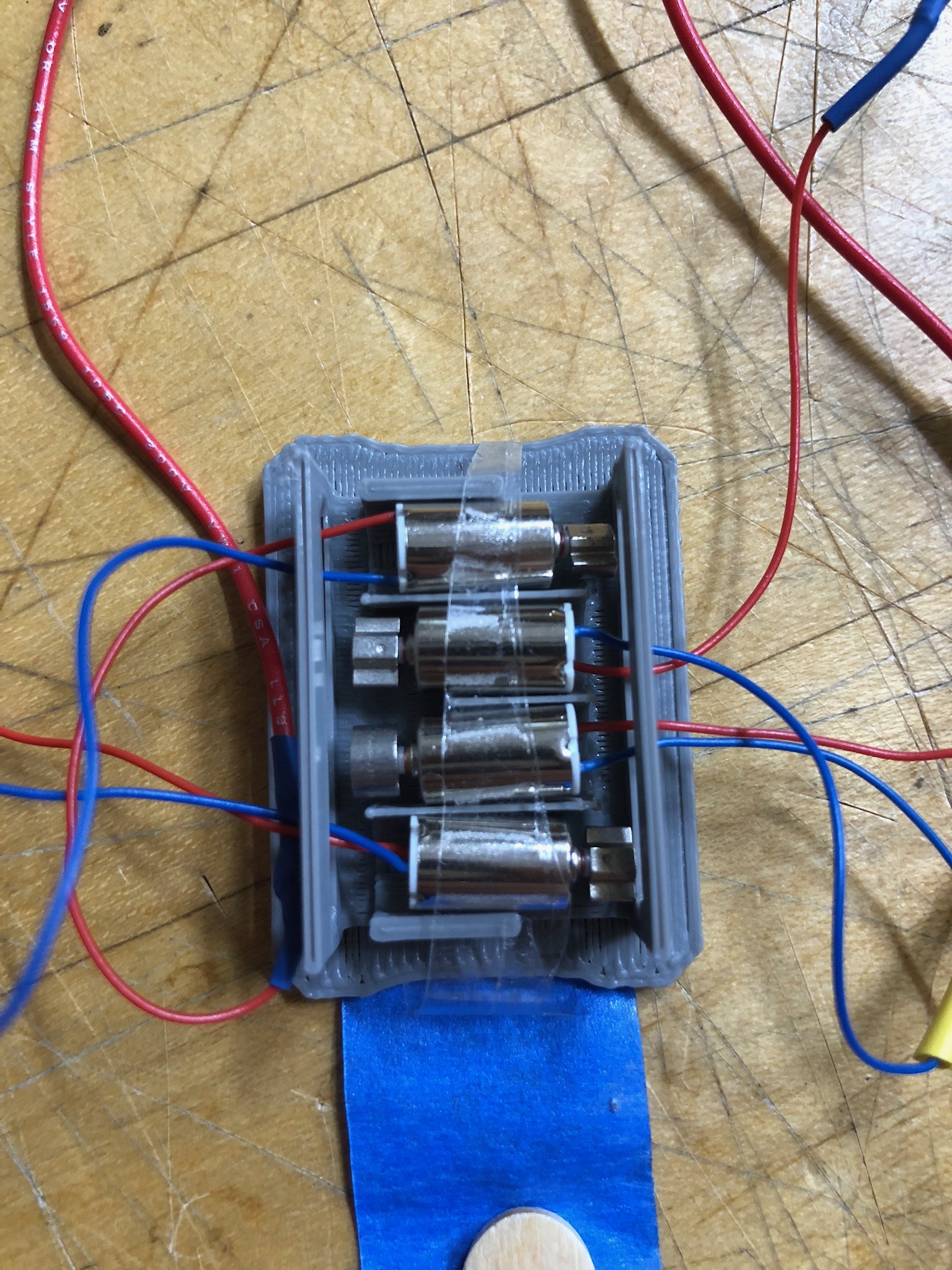
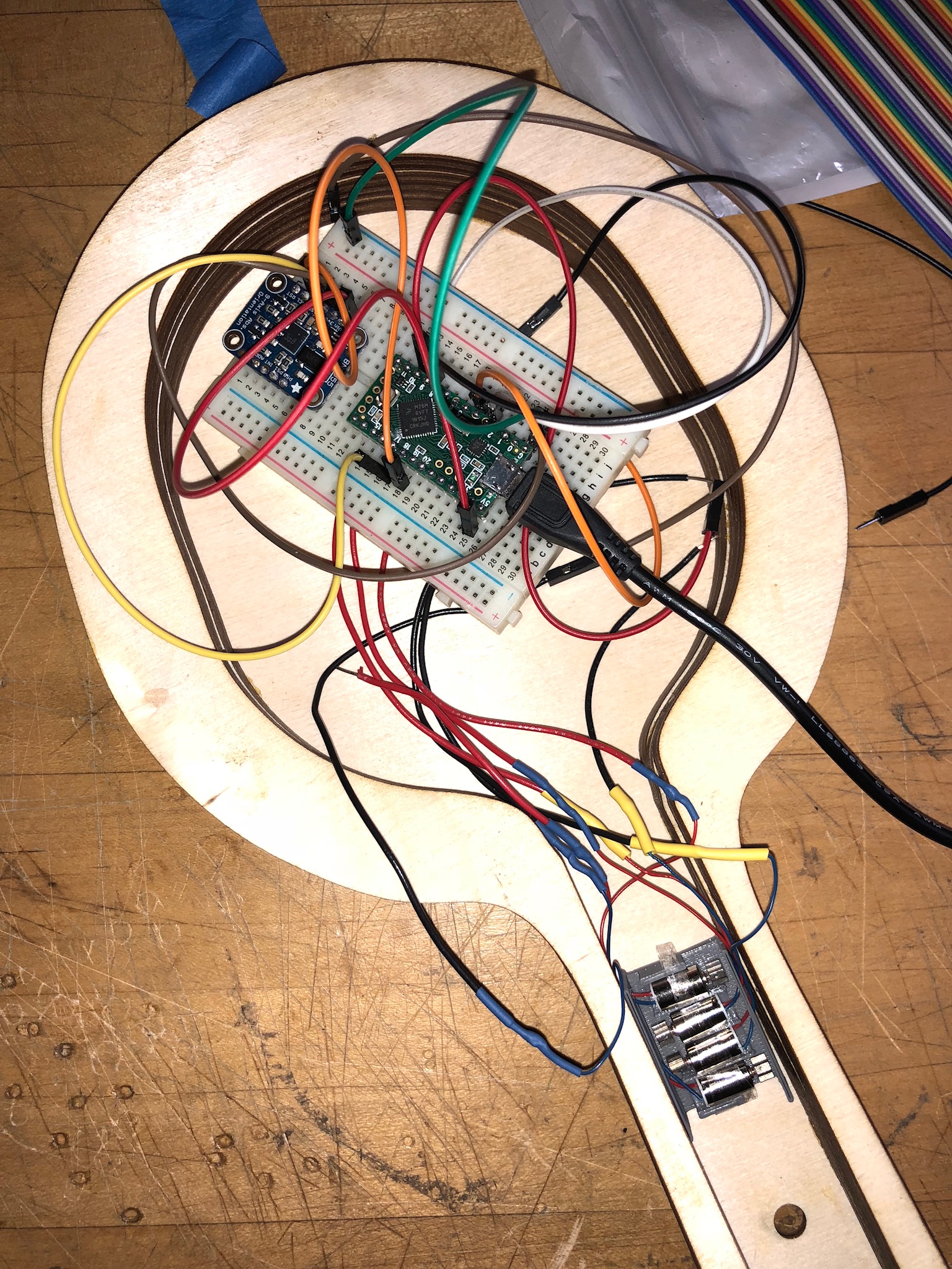
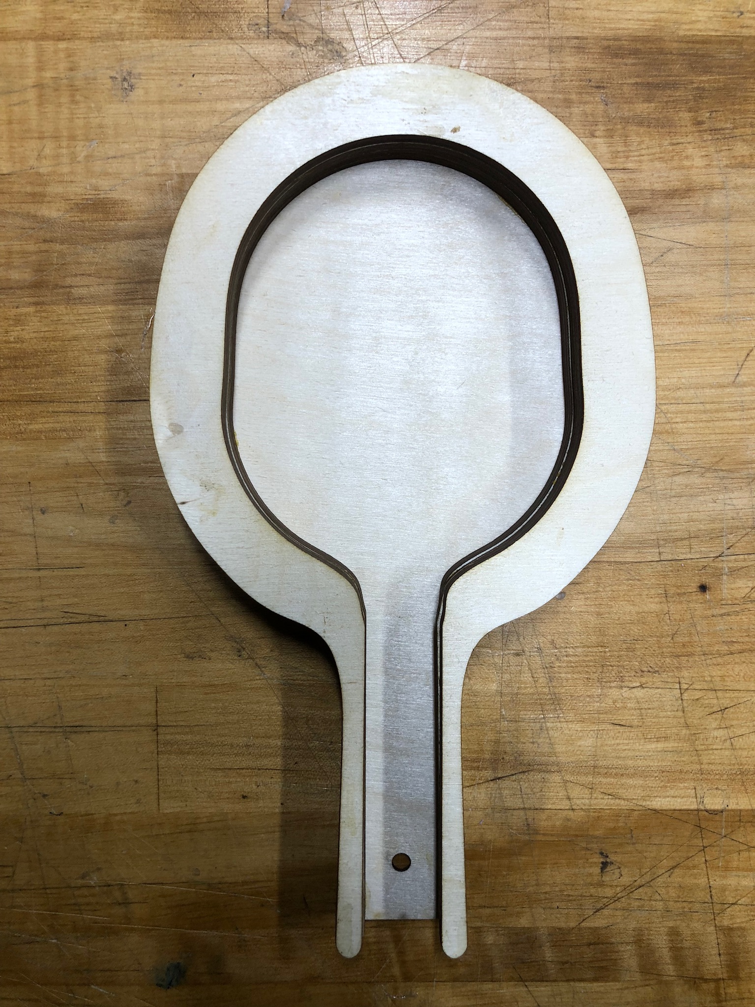
Here we have our breadboard with our Arduino Teensy and IMU connected to the motors.
Goal 2: Code
For the motors, the PWM output values can be written from 0 to 255. After some testing, we figured that the 150 has to be the minimum value that has to be output to the motors, in order for the users to feel a light vibration (equivalent to the ball gently bouncing on the motor). The maximum is 255. We decided to connect our 4 motors to separate PWM pins instead of connecting in series so that each motor would have maximum power and vibration.
In terms of dynamics and forces on the paddle, upon impact, we decided that:
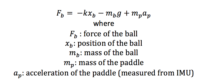
We will scale the force from the ball by a certain scaling factor, such that the maximum power will be 255.

We will need to do more testing to figure out an accurate number for the scaling factor, but we know that the value of scaling*Fb ≤ 255-150 = 105. We will do the calculations by figuring out the ballpark values of the acceleration of the paddle, ap, from the IMU sensor, calculate Fb and then calculate the ideal scaling factor.
In other cases, the force on the paddle = 0 (when the ball is in the air), so the code will just be analogWrite(motorPin, 0);
To find the position of the ball so that we can output it in processing using the Serial.println() command, we will essentially find the acceleration of the ball, ab, after dividing the force of the ball, Fb by its mass. We will then integrate acceleration twice to find its position.

Goal 3: Processing

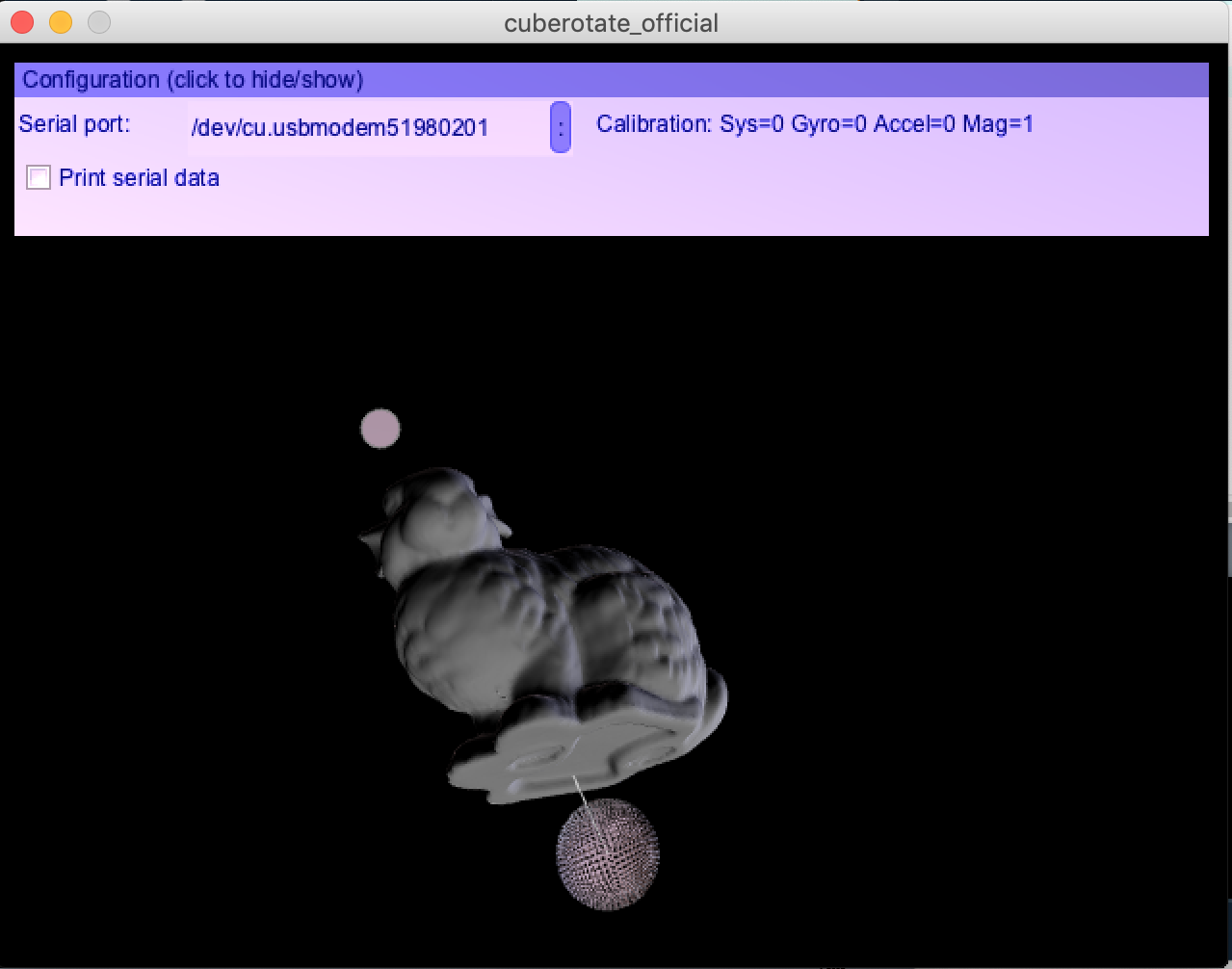
We are currently exploring various ways to display our paddle in Processing. In the left image, we have rendered a paddle with a string attached, and it can show a ball bouncing up and down (this is without the IMU). In the right image, we managed to integrate our IMU output into processing, with the rabbit being the mock up of the paddle (we'll change it later), and we managed to attached a string and ball to it as well.

