

Xiyang

2-DOF PANTOGRAPH HAPTIC DEVICE FOR GENERAL EDUCATIONAL PURPOSES
Project team member(s): Xiyang Yeh
The aim of the project is to design a low cost 2 DOF haptic device for education purposes. To demonstrate the capabilities of the system, a simple application teach world geography is proposed. The entire project development went smoothly and the entire system including the software were successfully implemented.
On this page... (hide)
Introduction
The haptic paddle has been a useful tool in teaching various concepts via haptic feedback. Since only 1 DOF is available, it constraints the user to move in a line. This limits the types of haptic rendering that can be done. The motion restriction also makes the user uncomfortable especially after prolonged use.
To open up new possibilities and extend the use of haptic capabilities in reinforcing learning, a 2 DOF planar mechanism is explored. To generate 2 DOF planar motions, we can either use serial or parallel linkages. Several design constraints and considerations need to be made to enable the widespread use of the 2 DOF device in an education setting:
1) Low cost and easily constructed
2) Portable
3) Easy to use and program
4) Good force capacity within a reasonable workspace area
The proposed application intends not only to demonstrate the capabilities of the design but also to explore how force feedback can enhance learning. In the typical classroom setting, students are given only visual feedback on where a country is on the world map. The application here attempts to incorporate forces that guides the user to the desired country in the world map to improve retention rate. An interesting aspect about force feedback is that it also conveys directional information. Take for example, when the proxy's desired location is changed from India to Russia, one feels a force pulling the proxy upward. This gives a sense of where Russia is relative to India.
Background
As mentioned in the previous section, the mechanism can be designed using a serial or parallel configuration. For serial linkages, the first link needs to carry the motor for the second link. This reduces bandwidth due to the increased moving mass. Compared to serial linkages, parallel linkages has a stiffer structure since all the parallel links contribute to the overall stiffness. In addition, parallel mechanisms also allow the motors to be located at the base to reduce moving mass. However, these mechanisms usually have complicated kinematic equations and limited workspace due to the presence of closed loops. Examples of serial and parallel kinematic commercially available robotic devices are shown below.

| 
|
| Fig. 1. (a): Quanser Serial robot with 2 revolute joints [1] | (b): Force Dimension Omega haptic device with 3 parallel legs [2] |
I decided to go with a parallel configuration mainly due to its higher structural stiffness. To ensure that the mechanism can provide sufficient force and workspace, some dimensional analyses will be required. For compactness, I decided to go only with revolute joints. The most common revolute joint only design discussed in literature is the 5-bar mechanism. Campion et. al. analyzed the forward kinematics of their pantographic 5-bar haptic device and quantified performance in terms of the kinematic conditioning of the jacobian matrix [3]. The paper also talks about mechanical issues such as backlash in the device and proposes ways to eliminate them. An et. al. explored the use of magnetorheological brakes in parallel with dc motors in their 5-bar device [4]. The paper provides some insight into cable tensioner designs.
In addition to the design, I also reviewed some publications related to haptics in education. Wong et. al. developed an inexpensive haptic device and used it for education in dynamics and controls [5]. Persson et. al. discussed about how haptics was used in biomolecuar education [6]. In Jones et. al.'s study, haptic feedback was incorporated into educating students about viruses and nanoscale biological entities [7]. The results from these papers indicated that haptics improved students' appreciation of the topics taught and abstract concepts can be effectively conveyed via force feedback.
Methods
Dimensional analysis
Since the motors are already selected, the only variables left are the gear ratios and link dimensions. Using the equations given in [3], the forward kinematics will be used in the workspace analysis and isotropic force output computation. The attached matlab file provides tools to visualize these analyses given the link dimensions and joint angles. Using the parameters specified in [3], the final selection is:
a1 = 0.1 m
a2 = 0.13 m
a3 = 0.13 m
a4 = 0.1 m
a5 = 0.06 m
Gear ratio = 17
Workspace
The workspace is computed by running through all the joint angles and transforming them to the task coordinates, in this case, XY locaiton of the end effector. The link lengths are tuned to such that the maximum force output is achieved given a square workspace of 100 mm side length.
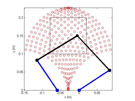
Fig. 2: Workspace of the device. The black box denotes the desired operation workspace.
Isotropic Force Output
The isotropic force is the minimum force that can be rendered by the device in any arbitrary direction. In this analysis, we consider only static forces.
We know that the transpose of the jacobian maps joint torques to task space forces. In configurations other than singularity, we can invert the jacobian, thus given the set of four permutations of minimum and maximum torques from the two actuators, we can define a output force parallelogram. The device can only render force vectors within this parallelogram. Thus, the smallest circle inscribed within this parallelogram defines the maximum isotropic force that can be produced.
Note that we can directly map the four sets of torques to vertices of the parallelogram instead of running through the entire set of actuator torques. This is because a the linear mapping from the jacobian inverse transpose preserves convexity.

Fig. 3: Isotropic force the can be produced by the device. Within the workspace, the isotropic output force is fairly constant at around 3 N.
Final Design
The final design is as shown in the Figure 4 below. We will use acrylic for the structure due to its cheap cost, nice transparent feature and high rigidity.

Fig. 4: CAD of the Pantographic Haptic Device
Electronic Setup
Motor
For the motors, note that flats has to be created first. This can be done cheaply by sending it to a machine shop in batches. Once the motors have flats on, we are ready to setup the electronics. The instructions are as follow:
(1) Solder the leads of the motors to wires and heat shrink the leads. Note that the red wire should go to the positive lead.
(2) To protect the motors, use cable ties to hold the wires to the motor's body.
PWM to Motor Currrent Mapping
Since we are using PWM to drive the motor, there is a need to map PWM duty cycles to motor current. To do so, we will first connect a multimeter in series to measure the current going into the motor. Next, we slowly increase the PWM duty cycle from the motor shield while holding on to the motor shaft. We will continue until we hit the maximum continuous current as specified in motor's datasheet (0.84 A for RE-MAX 29 #226751). Finally, with the gather data we perform a 2nd order polynomial fit on the (duty cycle, current) data (see attached matlab file). My calibrated function is shown in Fig. 5.

Fig. 5: Duty cycle to motor current mapping
MagnetoResistive Sensor
To sense position of the joints, we use a KMA199E (http://www.nxp.com/documents/data_sheet/KMA199E.pdf). Setup is simple in that we only need to solder the 3 wires (+5Vdc, GND and Signal). Referring to [3], I connected the sensor signals of theta_1 and theta_5 to A0 and A1 pins of the Arduino board respectively.
Hardware Design and Implementation
The CAD model for the entire design can be found in the FILES section below. All the acrylic pieces required can be cut out from a 24"x24" acrylic sheet using the included .dxf file. Although a 1/4" thick acrylic was ordered, I received a 0.23" thick sheet. This did not create any problems as I only needed to include some washers for the 3" 8-32 screws.
For the construction, it is mainly split into 5 parts: (1) base, (2) arms, (3) cover (4) integration and (5) cabling . The instructions will be explained in details in the follow sections.
Base
The final assembly is shown in Fig. 5. Before assembling, several components need to be preprocessed. For the base, we need to first cut the 3/16" shaft into three 3.2" long shafts. Since these shafts are meant to align the acrylic pieces, they do not need to be extremely precise. Secondly, we need to tap all the screw holes for the bottom piece. All the 6-32 and 8-32 screw holes must be tapped in the same direction. Finally, reamers are required for all the 3/16" holes. I used a 0.1865" diameter reamer so that the 3/16" shafts can be press fitted. Now, we are ready to assemble.
(1) Starting from the top piece, use a mallot to insert the 3/16" shafts. Use a spacer below the piece to let some of the shaft pop out from the other side.
(2) Use the protruded shaft ends to align the next acrylic piece.
(3) Repeat steps (1) and (2) until the last piece is assembled. An arbor press will come in handy for the third acrylic piece onward.
(4) For the two holes that will be used with 1/4" sleeve bearings, ream them with a 0.374" reamer.
(5) Press fit the sleeve bearings.
(6) Screw the bottom two pieces together with 6-32 screws.

Fig. 6: Device base.
Arms
The procedure to assemble the two arms (see. Fig 6) are quite similar to that of the base.The arm consist of two links: proximal capstan drum and distal passive link.
(1) Using a 0.124" reamer, ream all the holes for the 1/8" dowel pins.
(2) Tap the 6-32 and 8-32 holes on the bottom acrylic sheet for the capstan drum.
(3) We will first assemble the capstan drum. Firstly, we insert all the 1/8" dowel pins.
(4) Next screw in all 8-32 and 6-32 screws. Leave out only the 6-32 screw that is used for the cable tensioner.
(5) Ream the two 1/4" dowel pin holes with a 0.254" diameter reamer and slot in the dowel pins. The capstan drum is done.
(6) Moving on to the passive link, start by reaming the holes for the bearings using a 0.374" diameter reamer.
(7) Press fit all the sleeve bearings.
(8) Install the dowel pins to hold the inner two (smaller) sheets of acrylic.
(9) Now, space up the outer two sheets with 0.063" shims.
(10) Bolt down the passive link such that it holds on to the capstan drum's shaft as shown in Fig. 6.
(11) Although the passive link for the other arm is slightly different, the steps are the same.
(12) Finally, we need to join the two arms with the 4" long 1/4" diameter shaft. This can be done by carefully spacing up the passive links and pressing it in using an arbor press. Alternatively, we can remove the outer acrylic sheets, press in the shaft and subsequently re-installing the outer acrylic sheets.

Fig. 7: Device arms.
Cover
The cover assembly is fairly straightforward. Note that for the motors, flats must be created before assembly.
(1) Ream all the 1/8" dowel pin holes for both the top piece and the two circular joint spacers.
(3) Tap the 6-32 holes for the joint spacers.
(4) Install the 7/16" long dowel pins and screw in six 6-32 screws.
(5) Now ream the holes for the sleeve bearings with the 0.373" reamer.
(6) Press fit the sleeve bearings into the holes.
(7) Using acrylic cement, glue in the two stands.
(8) Using a 4-40 tap, tap the capstan pulleys' set screw holes.
(9) Install the capstan pulleys at both motors and tighten the set screws.
(10) Mount the motors by installing twelve M2 screws together with M2 washers.

Fig. 8: Device cover.
Integration
With the base, cover and two arms completed, we are ready to integrate them.
(1) Slot in the two arms into the base.
(2) Put six acrylic base spacers with two 0.062" shims in each of the four 8-32 holes. Tapes will come in handy here.
(3) Mount the cover by press fitting the 3/16" shafts into the corresponding holes and screwing in four 3" 8-32 screws.
(4) Slot the magnets into magnet holders and press fit one holder into each of the capstan drums' shafts.
(4) Finally bolt in the magnetoresistive (MR) sensor holder and mount the cover for the MR sensor stands.

Fig. 9: Full integration of mechanical components.
Cabling
Cabling can be difficult if you are doing it for the first time. This is because, the cable will need to be tensioned as you wrap, otherwise it will unwrap itself. To facilitate the process, you can either ask another person to make sure the wrapped cable is taut while you wrap or you can use a tape to hold the cable down. In my design, I used 0.024" diameter cables (#2024) and 1/32" stop sleeves (#8030C) from Sava Industries, Inc. (http://www.savacable.com/pages/steel_cable.html) which were available in my research lab. In the included bill of materials, I specified corresponding McMaster parts so that everything required can be purchased together from McMaster if one decides to replicate my device. Fig. 9 displays the tools that are commonly used in the assembling of cable drives.

Fig. 10: Cabling tools. From left to right: torch, cable cutter, crimper
Now, with the tools, we can start the cabling process. The steps are as follows:
(1) When the cables are shipped, the ends may have frayed. This makes slotting it into the stop sleeves challenging. To address this, we burn one of the ends of the cable and cut the burnt part with a cable cutter.
(2) The burnt regions are weaker but the cables are held together. Using this end, first slot in a stop sleeve and then a 2 mm washer.
(3) Move both components to the other end of the cable and crimp the stop sleeve.
(4) Slot the cable (from the end without the stop sleeve) into the capstan drums from below, i.e. into the squarish holes.
(5) Once the cable pops out from the circular guide in the capstan drum, pull until the stop sleeve and the washer goes directly into the square holes. Generally, if the capstan drive is made out of steel or aluminum, the washer is not needed. However, since we are dealing with acrylic, we need to distribute the stress from the stop sleeve. Without the washer, the regions near the stop sleeve may break.
(6) Now with the cable taut, wrap the cable around the capstan pulley. Since we have limited grooves in the pulley, make sure that we have enough cable walk. The cable should not go out of the grooved region for the entire workspace of the capstan drum.
(7) Insert a hex nut into the hexagonal hole below the capstan drum. Also, slot in the corresponding 1" long 6-32 screw.
(8) Sandwich the cable with two #6 washers and loop it around the screw. Make sure the loop is done clockwise looking from the head of the screw. The clockwise arrangement enables us to keep the cable taut while tightening the screw later.
(9) Tighten this screw to the hex nut.
The cabled capstan drum is shown below.

Fig. 11: Cabled capstan drum
System Control
At this point, we already can compute the torques using T = Kt * I, where Kt represents the torque constant specified in the motor datasheet and I denotes the current through the motor. The required current can be generated by varying the PWM duty cycle according to the mapping explained in earlier sections. To fully control the robot, we need to sense the joint angles, i.e. theta1 and theta5. As such, we will have to map the ADC readings from the MR sensors to joint angles. We will be using the calibration sheet (see Fig. 11) included in the CAD folder. By placing the robot on the sheet and recording the corresponding ADC reading as the joint moved to the lines, we can fit a map function using polynomials. This is essentially the same process as that used to map PWM to current.

Fig. 12: Joint angle calibration sheet.
Since the kinematic equations of the system in [3] are fairly complicated, I decided to move the computation to the computer. The entire message passing protocol using UART at 115kbps baud rate is shown in Fig. 12. A simple cpp program that simulates a virtual wall can be downloaded from the link below.

Fig. 13: System overview. Messages are passed using UART at a baud rate of 115 kbps.
Educational Demonstration
To demonstrate the device, a simple world geography application was programmed with chai3d (http://www.chai3d.org/). The code is attached below. Since I used a later version of the chai3d library that has not be been released, the code may not function properly. For those who are interested in developing haptic applications with this device, the included virtual wall application will serve as a good starting platform.
In the world geography application, the user is guided through a series of countries in the world map. For every country, a spring is setup between the proxy, i.e. haptic device location in the scene and the country location itself (see Fig. 12). The user will thus feel a pulling force toward the country. Once the proxy is close enough to the country, the name of the country appears.

Fig. 14: World geography application.
The entire system with the world geography application is shown below:
Results
Most of the users at the open house responded that they have learned a little bit more about other countries. Some commented that providing the user with more authority may yield better result. Instead of having the device guide them at all times, they prefer it to only guide them when they are close enough to the country of interest. In this manner, they have to make intelligent guesses as to where the country is approximately at.
Future Work
For future work, I would recommend several modifications. Firstly, several improvements need to be done for the capstan pulley. The grooves served as stress concentration points and made the pulley weak especially against lateral forces. As such, grooves should be removed. In addition, since the material used for the pulley is brittle, the threads in the set screw hole wear of easily. To address this, the pulley should be made bigger in size and set screws with bigger pitch and deeper threads should be used.
As for the world geography application, it should encourage more active exploration rather than just providing full guidance. A better approach will be to only exert pulling forces when one is near the country of interest. This will engage students to actively search for it.
Files
https://dl.dropbox.com/u/30618321/Website/xy_final_project.zip
References
[1] Quanser. "2 DOF Serial Flexible Joint". Retrieved from http://www.quanser.com/english/html/products/fs_product_challenge.asp?lang_code=english&pcat_code=exp-spe&prod_code=S30-2DSFJ&tmpl=1
[2] Force Dimension. "Omega.3". Retrieved from http://www.forcedimension.com/omega3-overview
[3] Campion, G.; Qi Wang; Hayward, V.; , "The Pantograph Mk-II: a haptic instrument," Intelligent Robots and Systems, 2005. (IROS 2005). 2005 IEEE/RSJ International Conference on , vol., no., pp. 193- 198, 2-6 Aug. 2005, Retrieved from http://ieeexplore.ieee.org/stamp/stamp.jsp?tp=&arnumber=1545066&isnumber=32977
[4] An, J.; Kwon, D.S.. Five-bar linkage haptic device with DC motors and MR brakes. Journal of Intelligent Material Systems and Structures, 21:1169-1191, August 2010. Retrieved from http://jim.sagepub.com/content/20/1/97.full.pdf+html
[5] Wong, C.E.; Okamura, A.M.; , "The snaptic paddle: a modular haptic device," Eurohaptics Conference, 2005 and Symposium on Haptic Interfaces for Virtual Environment and Teleoperator Systems, 2005. World Haptics 2005. First Joint , vol., no., pp. 537- 538, 18-20 March 2005. Retrieved from http://ieeexplore.ieee.org/stamp/stamp.jsp?tp=&arnumber=1406999&isnumber=30512
[6] Persson, P.B.; Cooper, M.D.; Tibell, L.A.E.; Ainsworth, S.; Ynnerman, A.; Jonsson, B.-H.; , "Designing and Evaluating a Haptic System for Biomolecular Education," Virtual Reality Conference, 2007. VR '07. IEEE , vol., no., pp.171-178, 10-14 March 2007. Retrieved from http://ieeexplore.ieee.org/stamp/stamp.jsp?tp=&arnumber=4161020&isnumber=4160977
[7] Jones, M.G.; Bokinsky, A.; Andre, T.; Kubasko, D.; Negishi, A.; Taylor, R.; Superfine, R.; , "Nanomanipulator applications in education: the impact of haptic experiences on students' attitudes and concepts," Haptic Interfaces for Virtual Environment and Teleoperator Systems, 2002. HAPTICS 2002. Proceedings. 10th Symposium on , vol., no., pp.279-282, 2002. URL: http://ieeexplore.ieee.org/stamp/stamp.jsp?tp=&arnumber=998971&isnumber=21555
Appendix: Project Checkpoints
Checkpoint 1
The final design is as shown in the Figure 1 below. We will use acrylic for the structure due to its cheap cost, nice transparent feature and high rigidity. To ensure good force output over a sufficiently large workspace, simulations were conducted.
Figure 1: CAD of the Pantographic Haptic Device
The workspace is computed by running through all the joint angles and transforming them to the task coordinates, in this case, XY locaiton of the end effector. The link lengths are tuned to such that the maximum force output is achieved given a square workspace of 100 mm side length.
Figure 1: Workspace of the Device. The black box denotes the desired operation workspace.
Isotropic Force Output: The isotropic force is the minimum force that can be rendered by the device in any arbitrary direction. In this analysis, we consider only static forces.
We know that the transpose of the jacobian maps joint torques to task space forces. In configurations other than singularity, we can invert the jacobian, thus given the set of four permutations of minimum and maximum torques from the two actuators, we can define a output force parallelogram. The device can only render force vectors within this parallelogram. Thus, the smallest circle inscribed within this parallelogram defines the maximum isotropic force that can be produced.
Note that we can directly map the four sets of torques to vertices of the parallelogram instead of running through the entire set of actuator torques. This is because a the linear mapping from the jacobian inverse transpose preserves convexity.
The isotropic output force in the desired workspace is shown in Figure 2 below. Within the workspace, the isotropic output force is fairly constant at around 3 N.
Figure 2: Isotropic Force the can be produced by the Device. Within the workspace, the isotropic output force is fairly constant at around 3 N.
Completed Tasks: With the analysis and the design in place, I have purchased most of the components. I'll be testing out the RE-MAX 29 motors used for this project and work out the PWM-to-force mapping. The acrylic pieces will be cut while waiting for the mechanical parts from McMaster.
Checkpoint 2
The acrylic pieces has been put together to form the final mechanism as seen in Figure 3. As for the low level controls, the motor's duty cycle to current mapping has also been completed (see Figure 4). Currently, the motors can both be independently controlled. The next step will be to incorporate kinematics to accomplish task space control.

Figure 3: Actual device
Figure 4: Duty cycle to motor current mapping
Checkpoint 3
The device is finally configured with proper communication protocol for task space control. Haptic effects are rendered using chai3d. A simple potential field haptic application demonstrating magnetic effect is shown in the following video:
Finally, with all the required elements setup, a complete integration with the proposed world geography application can be done. The full system is shown below: