Anthony Bombik Jayant Mukhopadhaya
Controlling Team Rocket's Hot Air Balloon
Anthony Bombik Jayant Mukhopadhaya
Abstract

Caption:
The Team Rocket Hot Air balloon
Being aerospace engineers we were fascinated by the buoyancy problem that a Hot Air Balloon presents. A hot air balloon works by heating air and lowering its density inside the balloon, creating a buoyant force that can lift the hot air balloon to the desired height. The goal is to control the dynamics of the hot air balloon to safely reach the desired height using a PID controller and a low pass filter. There is drag that damps the movement.
The advanced feature will be inclusion of non-linear drag.
Introduction
In every episode of the original Pokemon TV series, Team Rocket would come in on their Hot Air Balloon attempting to steal Pokemon. However, Team Rocket was never successful. Their balloon would always explode and they would miss out on the opportunity to grab Pikachu (https://youtu.be/TGfsSQFemkc?t=236). Our goal is to design a controller to control the altitude of their balloon in order to navigate and steal Pokemon. It will be difficult because drag varies with the square of velocity, making the system nonlinear. Although the foundation for the problem comes from something fictional, this could actually be applied to real world applications and would make traveling by hot air balloon a little safer.
Plant Model
1) Description of the Model:
We are modeling a hot air balloon with gravity, the force from buoyancy, and including nonlinear air drag. In order to simplify the control, we modeled the force to cancel gravity and result in equilibrium if the value of the force is 0. This means that occasionally the controller will ask for a "negative" value of force, but actually the force should just be slightly less than the weight so that the balloon lowers slowly. The free body diagram can be seen below:

2) Derivation of Time Domain Equation of Motion and Parameters:
Since we are interested in the control of the height of the hot air balloon, the system is a simple one degree of freedom system. Solving the Free body diagram, we get the following equation of motion:
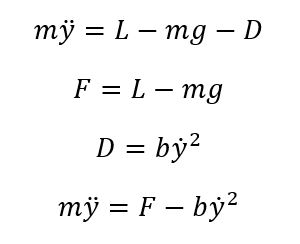
The complexity of the Equations of motion (non linear drag) prevents us from providing the Laplace domain equations. Where the parameters are:

Since we cannot expect the hot air balloon to instantaneously reach the desired height, two ramp inputs are used to create a reference signal that increases the desired height at 3.5 m/s to the final value. The final value can be changed in the MATLAB script to see the performance of the controller at different values. The 3.5 m/s ramp is chosen as a commercial hot air balloon rises at about 3 to 4 m/s.
The various parameter values were taken from sources linked in the reference section. The values are for typical 3 person hot air balloons.
3) Open Loop system
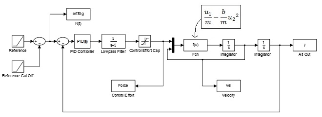
The open loop block diagram built in simulink can be seen below. A mux is used to implement the non-linearity of the system. The equations of motion dictate the user defined function.

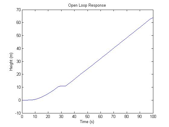
Below is the open loop step response. A step input of 100 is used. This corresponds to a reference signal that is asking the hot air balloon to reach a height of 100 m. The open loop response is unstable. It also is very slow to reach the desired height. The need for an appropriate controller is evident.
Control Design
1) Control Design Description:
We started with a PID controller and changed the values until we had a reasonable rise time for a hot air balloon. Looking at references online we determined that an ascent rate of 3-4 m/s is a reasonable ascent speed. Higher speeds would cause ear trauma because of the rapidly changing air pressure. This was the basis of our rise time specification. We then worked on steady state error and damping to get a smooth and accurate control for the passengers.
When we plotted the control effort with respect to time, we noticed unreasonable values for the Lift Force. From references online, we found that a Hot Air Balloon can generate about 8000 N of force. Subtracting the weight of the balloon gives us a maximum control effort of about 3000 N. We used a saturation block to implement this limit in our controller. This 3000 N of lift corresponds to an ascent velocity of greater than 4 m/s which would not be reached because of the nature of our reference input. But we left the saturation in there as a fail safe in case the controller does ask for a large lift force.
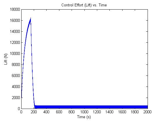
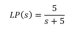
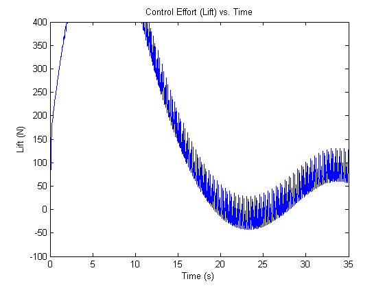
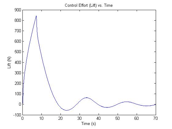
Another problem we noticed with the control effort was some high frequency noise. Upon analysis of the plot, the frequency of the noise was determined to be about 6 Hz. This prompted us to place a low pass filter with a cutoff frequency of 5 Hz before the saturation block.
Before the Low Pass filter is added:
After the Low Pass filter is added
2) Mathematical Expression of Controller
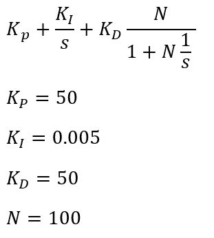
We used a classic PID control for our design. This resulted in the following transfer function:
3) Closed Loop Block Diagram
Which led to the following closed loop block diagram:
4) Derivation of Control Parameters
We started with a closed loop system that had a very slow response time, so we added a large proportional controller to reduce the response time. Once the rise time was reasonable, our damping was quite low and the response oscillated for a long time, so we added a derivative controller to reduce the settling time. This was tuned damp out the oscillations after about 2-3 overshoots. At this point we were able to see there was some steady state error in the system so we added and modified an integral controller until the steady state error was less than 0.5%. The integral control had to be quite small because the time scale is quite large and would integrate error very quickly and reach very large values.
The additional outputs are used to check the velocities reached and the lift force that is required for the given response.
Results
The controller design was very successful and versatile. It was able to handle any positive value for height. These can be seen from the graphs below. The left graph represents closed loop system behavior. The middle graph is the velocity of the hot air balloon and the right graph depicts the control effort. From the left graph we can see how the reference signal ramps from 0 to the desired height. As explained earlier, this is to simulate the realistic movement of the hot air balloon (the balloon cannot suddenly be at 25 m).
For a desired height of 25 m:

For a desired height of 100 m:

For a desired height of 500 m:

In the last graph we can see the hot air balloon reach the cut off velocity of 3.5 m/s but the maximum control effort of 3000 N is not reached.
Conclusions
We believe the simulation and system response were quite satisfactory in the context of the application. The hot air balloon reaches the desired height without exceeding the limits placed on the lift generation by buoyancy. The system fails when we enter negative values of height. The overshoot increases when the height is very small ~1 m but that is to be expected as it is difficult to control a large mass over a short distance. If we had more time to work on the project, we would like to control for negative values of height. This would simulate the hot air balloon reaching a certain height and then descending to the ground (or any other lower height). We could also include the effect of wind disturbances (modeled as sine waves) and see if the controller can compensate for it.
Files
Matlab code and simulink models uploaded as a zip file.
The control performance can be tested for different heights by changing the value for dH
References
Wikipedia article on Hot Air Balloons: https://en.wikipedia.org/wiki/Hot_air_balloon
Hot Air Balloon Physics: http://www.real-world-physics-problems.com/hot-air-balloon-physics.html
Article on Team Rocket's Hot Air Balloons: http://bulbapedia.bulbagarden.net/wiki/Team_Rocket%27s_mechas#Team_Rocket.27s_Meowth_balloon

