

Daniel Washington Nabil Wessel
Attitude Control
Nabil Wessel, Daniel Washington
Abstract
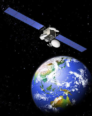
Our world is shaped by the presence of communications satellites in orbit around the earth. Everything from long distance phone calls to internet radio, to cell phone service in remote parts of the world rely on accurate satellite communications enabled by attitude or facing direction control. The problem of satellite attitude control is an entire field of study on it's own, but through this project, we hope to skim the surface of attitude control and learn how to design a reasonable controller that can both perform maneuvers common to satellites and correct against common disturbances to them. For our project, we will be designing around a medium sized communications satellite in low earth orbit subjected to atmospheric drag, micro-meteoroid collisions, and various pointing maneuvers, with the goal of developing a control scheme that is feasible in the amount of torque required from the craft as well as the time and accuracy of response.
The "Advanced Feature" of our project will be the nonlinear effect of the drag force on the orientation of our satellite. We will do all simulation and analysis in simulink to accurately capture all non-linear drag effects.
Introduction
For our project, we will be analyzing and developing the tools needed to control the orientation of a satellite in orbit. These problems are commonplace in both the private sector through applications in satellite internet and SIRIUS XM radio, as well as the public sector through the masses of NASA and governmental surveillance missions. The overall goal of our project is to familiarize ourselves with the types of control needed onboard satellites to ensure the proper orientation of a spacecraft to ensure two way communication. For our project, we will be looking primarily at satellites in Low Earth Orbit (LEO) which constitute a majority of all orbiting craft today, because this class of spacecraft represents both the fastest orbital period as well as exposure to the largest orbital perturbations.
Plant Model
Plant Model Description
The model for our plant is deceptively simple. At it's core, the space craft in an earth-centered frame has equations of motion that start as I*d2theta/dt2 = torque. The system is in an environment such that there is no linear damping due to the small effects of aerodynamic drag at low rotational speeds, and there is no spring force acting on the craft. The only external torque we chose to model is the dominant one on satellites in low earth orbit: Aerodynamic drag. Our craft is moving about the earth at 7.6 kilometers/second which creates a substantial amount of drag, despite the very low density at 400Km altitude. Additionally, the center of pressure is dependent on the direction the craft is facing relative to earth and is not in the same location as the center of mass, but rather is separated by a vector r, and therefore, the torque exerted on the craft is a function of the angle theta.
The time domain specification for the model can be found in the derivation in-line image. Because of the non-linearities present in the drag term, we could not find a Laplace transform but rather modeled the equation in simulink as shown below.
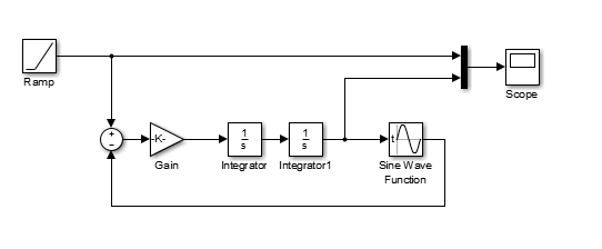
Plant Simulink Model
The following plant shows a satellite in a low earth orbit subject to a torque due to atmospheric drag. The input of the plant is torque and the output is theta from the reference point such that if the satellite is facing earth, theta will be equal to 0 radians. It consists of a 1/s2 term and a cosine term. Gain for the s2 term is 416.7 Kg-m2 and the sin function is -1.174*10-4N-m * sin(theta + pi/2).
Plant Derivation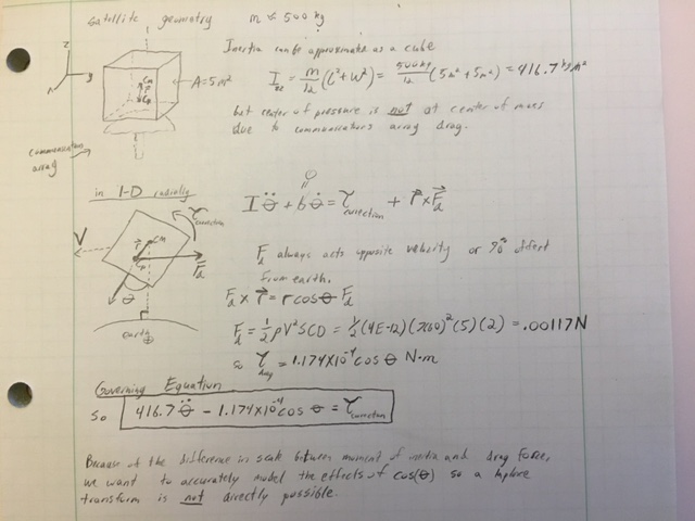
Parameters List
All orbit-specific parameters are taken from orbital data of the International Space Station
Assume circular orbit to enable us to operate in 1 dimension
Satellite specific parameter are estimated from documentation on "typical" LEO satellite dimensions and CG information
Satellite assumed to be a cube of mass 500 kg (medium small satellite commonly found in LEO)
Atmospheric damping assumed to be zero due to extremely low density
- Orbit height: 400 Km
- Atmospheric Density (rho): 4*10-12 Kg/m3
- Orbital Velocity (v): 7660 m/s
- Orbital period (tperiod): 5561.4 s
- Frontal area (S): 5 m2
- Coefficient of Drag (CD): 2
- Distance from center of mass to center of pressure (r): 0.1 m
- Moment of inertia (I): 416.7 Kgm2
Open Loop Plant Behavior
Input: The input signal for this case is a ramp input of 2pi radians/90 minutes. This input represents a very typical case where the satellite is required to complete one full rotation about it's axis over the course of a single 90 minute orbit.
Output The output signal of the simulation is the rotation of the spacecraft, theta. The observed output is actually very closely matched to that of the input in the very short term, but the constant force of drag on the spacecraft quickly causes it to tumble out of control as time goes on, preventing it from serving as an effective low earth communications satellite, as is our goal.

Control Design
Overview
The problem is, in it's simplest form, an undamped mass in space resulting in a second order linear transfer function. However, we will include the effects of drag in our analysis, which will make our system nonlinear due to the angle at which the drag force impacts our satellite. In addition to the non-linear effects of drag, we will examine the effect of three different inputs to our system: an impulse, modeled by a micro-meteoroid collision, a step, modeled by a desired pointing angle, and a ramp modeled by a progressive pitch maneuver. These inputs and responses are modeled exclusively in Simulink due to the non-linearity, and our controller of choice is a PID with a fast pole, which allows our system to adequately track signals from an impulse up to a ramp input and achieve desired settling time and maximum overshoot. We will design our controller by first linearizing our equations of motion about theta = 90 degrees, and then use Routh analysis and imposed restrictions on maximum overshoot and settling time to designate values for Kp and Kd. We will then incorporate integral control with a small Ki and designate a fast pole one order of magnitude greater than other system parameters.
The first step we took in designing our controller was linearizing our plant to get a sense of what sort of system we were dealing with. We saw that we were dealing with a second order system without any damping. This suggested we would need a PD controller because we needed a term to provide damping to the system. We then plotted the magnitude-time response to a step input of the non-linearized plant in Simulink to see what the actual plant was like. The non-linear term in our plant was the cos(θ) term, which created an oscillation that lingered in our system response. We knew we would not be able to completely eliminate this oscillation, so we would have to choose our controller parameters in such a way that the amplitude of the cos(θ) term would not exceed some error. After choosing these parameters and simulating our system in Simulink, we realized that our system still had some steady-state error because the lingering oscillation of our steady-state was about a line slightly below the reference input line. We decided to switch over to a PID controller to eliminate the steady-state error.
Up to this point in our design we had chosen parameters based on an arbitrary step input.
Complete Simulink Model

When we were still using a PD controller, we derived the accepted range of values for K_D and K_P using a Routh array. We found that our system would be stable for K_D>0 and K_P>-F_D, where F_D is the magnitude of the force of drag on our satellite.
Routh Array Stability Analysis - PD Control
s^2: I K_P+F_D
s^1: K_D 0
s^0: b_1=K_P+F_D
Even though our system was stable, it was still unacceptably slow to settling and with an excessive overshoot. We decided we wanted an overshoot less than or equal to five percent and a settling time of one second. Using these design parameters, we ended up with K_D=200.7 and K_P=50.
It was at this point that we realized our system still had steady-state error and we switched to a PID controller. We used another Routh array to determine the range of stable values for K_P, K_D, and K_I. We found that our system would be stable for K_D>0, K_I>0, and K_P>-F_D. The Routh array is listed below:
Routh Array Stability Analysis - PID Control
s^3 I K_P+F_D
s^2 K_D K_I
s^1 b_1=(K_D∙(K_P+F_D )-I∙K_I)/K_D 0
s^0 b_2=K_I
For some reason however, these conclusions did not hold in our Simulink model. Our system was unstable with all our constants equal to one, which fulfilled the Routh constraints. We decided to use the values of K_D and K_P that we had determined when designing our PD controller. This resulted in a stable system, so we decided to use them along with K_I=1.
At this point in our design process we realized that we were not designing for a realistic situation. We decided we wanted to design our satellite to respond appropriately and realistically to a micro-meteorite collision. This meant our overshoot and settling time values would have to change so that our controller effort would be more reasonable.
Design Parameters
- Maximum Overshoot <= 50%
- Settling time <= 5 seconds
PID Design Analysis

Results
Micrometeoroid collision (Impulse Response)
The first test we ran on our satellite control system is a simulation of an impact with a micrometeoroid. This represents a very real and very serious challenge that satellites in low earth orbit must overcome, as there are a huge number of objects in orbit around the earth that are uncontrolled and unmonitoried. These objects range in size from micrometers to an excess of 10 cm, and orbit the earth at approximately 10 Km/s. Objects in excess of 1 cm in diameter can prove catastrophic to a satellite on impact, but those of a smaller diameter can still cause serious problems on impact. For this reason, we chose to examine an impact with a spherical solid steel piece of debris (density of 8050 Kg/m2) moving at a relative velocity of 3 Km/s relative to our craft and a diameter of 0.5 cm. This was modeled with a unit impulse and a gain equal to the angular impulse of the collision, assuming it occurs 1 m from the center of mass.
- Input: impulse disturbance at t=3s of 1.58 N-m, discrete width of 0.01s
- Output: Theta of the satellite relative to earth reference direction
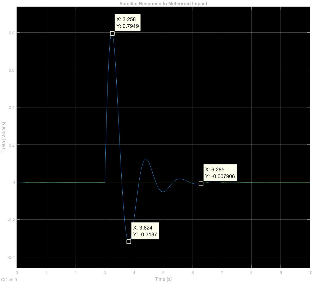
Test Results:
- Maximum Overshoot = 40%
- Rise Time = 0.258 seconds
- Settling Time to 1% of steady state = 3.285 seconds
These results show that we successfully replicated our desired response of Mp < 50% and a settling time of 5 seconds. This represents our satellite settling to an acceptable pointing accuracy of 1% within our 5 second benchmark.
Desired facing angle Test (Step Response)
The second test we decided to do is test fidelity of our controller by feeding our satellite a step response, which represents the occasional need to face a predetermined angle that is not directly toward earth.
- Input: 10 degree step response beginning at t = 3 seconds
- Output: Spacecraft facing angle relative to earth reference direction
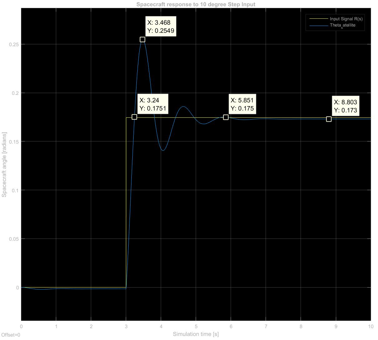
Test Results:
- Maximum Overshoot = 45%
- Rise Time = 0.240 seconds
- Settling Time to 1% of steady state = approx. 2.85 seconds
These results show that we successfully replicated our desired response of Mp < 50% and a settling time of 5 seconds. This represents our satellite settling to an acceptable pointing accuracy of 1% within our 5 second benchmark.
Progressive Pitch Maneuver
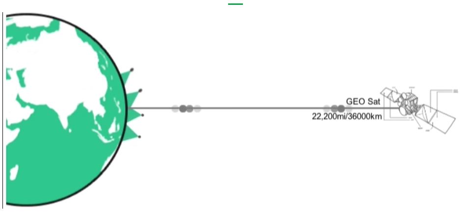
One further application of satellite control comes from the need to avoid communication overlap between the satellite in question and those at higher altitudes - namely GPS. If a communications satellite were to overlap with the orbit of a GPS satellite, the signal strength would deteriorate. Therefore, companies such as Oneweb, who seek to provide world wide satellite internet coverage has developed a maneuver called progressive pitch, which involves increasing theta on approach at the equator, and decreasing it to 0 degrees after passing it.
The idea as demonstrated on the Oneweb Website:
The control signal we designed is as follows:
 The signal consists of:
- A ramp of 0.16 degrees per second, starting at t=10, theta = 0 and ending at t=150, theta=23 degrees
- A step at t=150 going back to 0 degrees
Signal Response
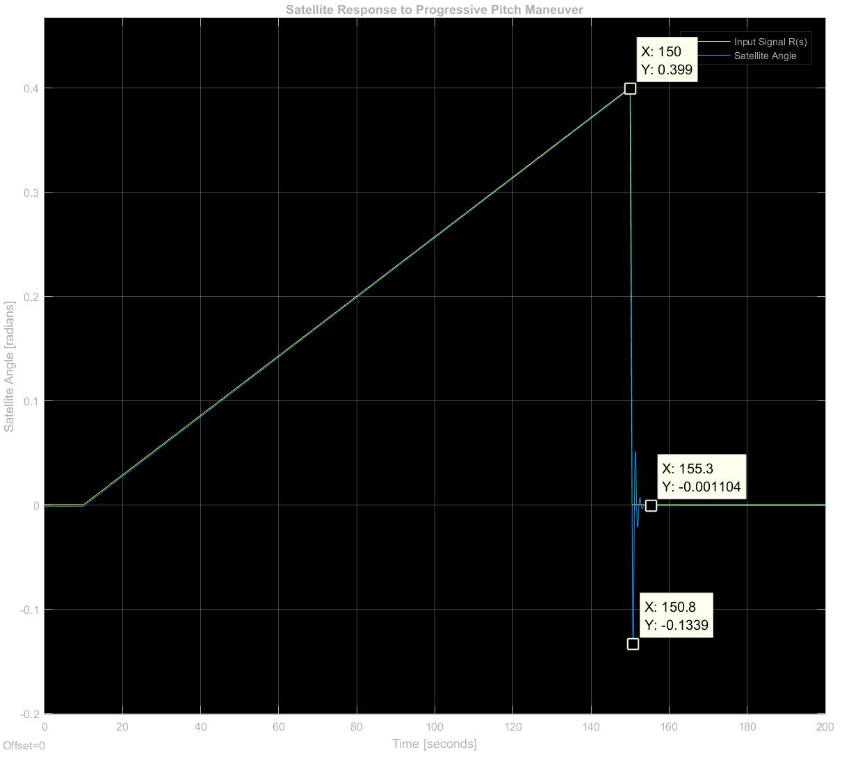
The response to our progressive pitch maneuver shows that the satellite is able to track the ramp input very accurately, and responds to the step back down to steady state in much the same manner as the unit step test we ran previously.
Conclusions
We set out to design a control system that would determine the orientation of a satellite in real time. Based on our simulations, we did in fact accomplish this. Correcting the error caused by a micro-meteoroid takes our controller about three seconds. If we had more time to work on this project, we would incorporate sensor noise in the satellite's feedback control to make our design more applicable to an actual physical system. We would also incorporate jet actuators into our satellite to control our satellite's linear motion in addition to its orientation. This would prove invaluable in correcting orbital trajectory after collisions or gradual orbit decay. The most important extension we would make to our control system however would be to incorporate control in multiple dimensions. The satellite exists in three dimensional space, so having a controller that only affects orientation and movement in one dimension is not very useful. Our work is a very good starting point though and demonstrates the basic principles involved in controlling a satellite.
Acknowledgments
Special thanks to Professor Andrew Barrows from Aeronautics and Astronautics for meeting with Daniel and helping brainstorm interesting ideas and applications of attitude control for LEO satellites.
Files
- Attached is a zip file containing the simulink model of our plant as well as the full controlled feedback model. The controlled simulink model has three differetn input blocks, corresponding to the three tests we ran on our controller.
Attach:Washington_project_file.zip
References
http://ocw.mit.edu/courses/aeronautics-and-astronautics/16-851-satellite-engineering-fall-2003/lecture-notes/l9_acs.pdf
http://www.daviddarling.info/encyclopedia/S/satellite_mass_categories.html
https://en.wikipedia.org/wiki/International_Space_Station
Spacecraft Attitude Determination and Control - James Wertz
http://www.nasa.gov/centers/wstf/laboratories/hypervelocity/mmod.html
http://oneweb.world/#technology
Wiki examples
Here is how to link to a file (note that you may need to compress/zip your code and CAD files into zip files so that that wiki will let you upload them, due to file type restrictions): Attach:HapkitTest.ino.zip
Here is how to add an image: 
Here is how to attach an image with the height adjusted (to 100 pixels)
Here is how to attach an image with the width adjusted (to 200 pixels)
Here is how to link a youtube video: