

Jeff Garnier Ryan Arata

HeliControls
Jeff Garnier and Ryan Arata
Abstract
In this project, Jeff and Ryan explore the control of helicopter angular positioning using the tail rotor swash plate actuator. The model describes how a stationary (hovering) helicopter responds to commanded changes in angle. The control system is implemented under the following constraints:
The goal of this control system is to have dynamic behavior for step input that is similar to a real helicopter. To this end, we set out to meet the following time specifications for a 180˚ step input (full turn around):
- 1. The rise time must be no more than 10 seconds while maintaining the max rotation speed constraint.2. The settling time must be no more than 30 seconds.3. The maximum overshoot must be less than 33%.4. The system must settle in two or less oscillations.
We implemented a proportional-derivative controller with a fast pole for each of the two controllers required by this system - one for the swash plate actuator and one for the entire helicopter system. The control design and exceeds these goals, with the following results:
- Rise time = 2.87s (max rotation speed = 56˚/s)Settling time = 21.5sMax overshoot = 25%System settles within the first oscillation
While the control system we developed meets the design goals, it has room to improve in other areas. The step response to a 180˚ change has the same time specifications as a 1˚ change, which makes the 1˚ change much slower than would be desired by someone controlling the helicopter. In addition, the rejection of disturbance is very weak, and the system therefore has large steady-state error in the presence of wind.
Advanced Feature: Our model includes a full-system transfer function of order four or higher.
Introduction
In this project, we explore helicopter yaw control. Jeff is a long-time quad copter enthusiast, and Ryan plans to work in the aerospace sector after graduation. The merging of our two interests resulted in this project, in which, instead of a pilot giving commands to the helicopter via a joystick, commands are given in the form of a desired rotation angle with respect to an arbitrary reference direction.
Helicopters with a single rotor produce torque on the rotors in a single direction to get lift, but the resulting equal and opposite torque makes the fuselage naturally rotate the opposite direction. In order to control the helicopter pitch, a tail rotor is mounted such that the blades are vertical in order to create a force in the horizontal direction far from the helicopter's center of mass to counter the torque of the main rotor.
Helicopter control (of both the main and tail rotor) is actuated not by changing the rotational speed of the rotors (which are directly geared together), but rather by actuating rotor angle to produce more or less lift. Typical airfoils have a nearly linear relationship between angle of attack and lift within a range of about -10˚ to 50˚, beyond which they stall and performance degrades quickly.
Plant Model
[Due 3/4:]
- Model Description
In order to develop a plant that describes the dynamics of helicopter control, we need to look at several different subsystems. We separated our overall plant into three separate parts: the swash plate plant, the blade lift plant, and the helicopter plant. The swash plate of the rear rotor system can change the angle of all blades simultaneously allowing for either an increase or decrease in lift. Variations in this lift force change the torque compensation and allow the helicopter to change its angle.
1. Swash Plate Plant
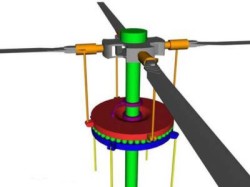
A swash plate consists of a stationary (outer) swash plate and a rotating (inner) swash plate. The stationary swash plate is connected to the rotors by a series of push rods and controls the angle of attack of the rotors.

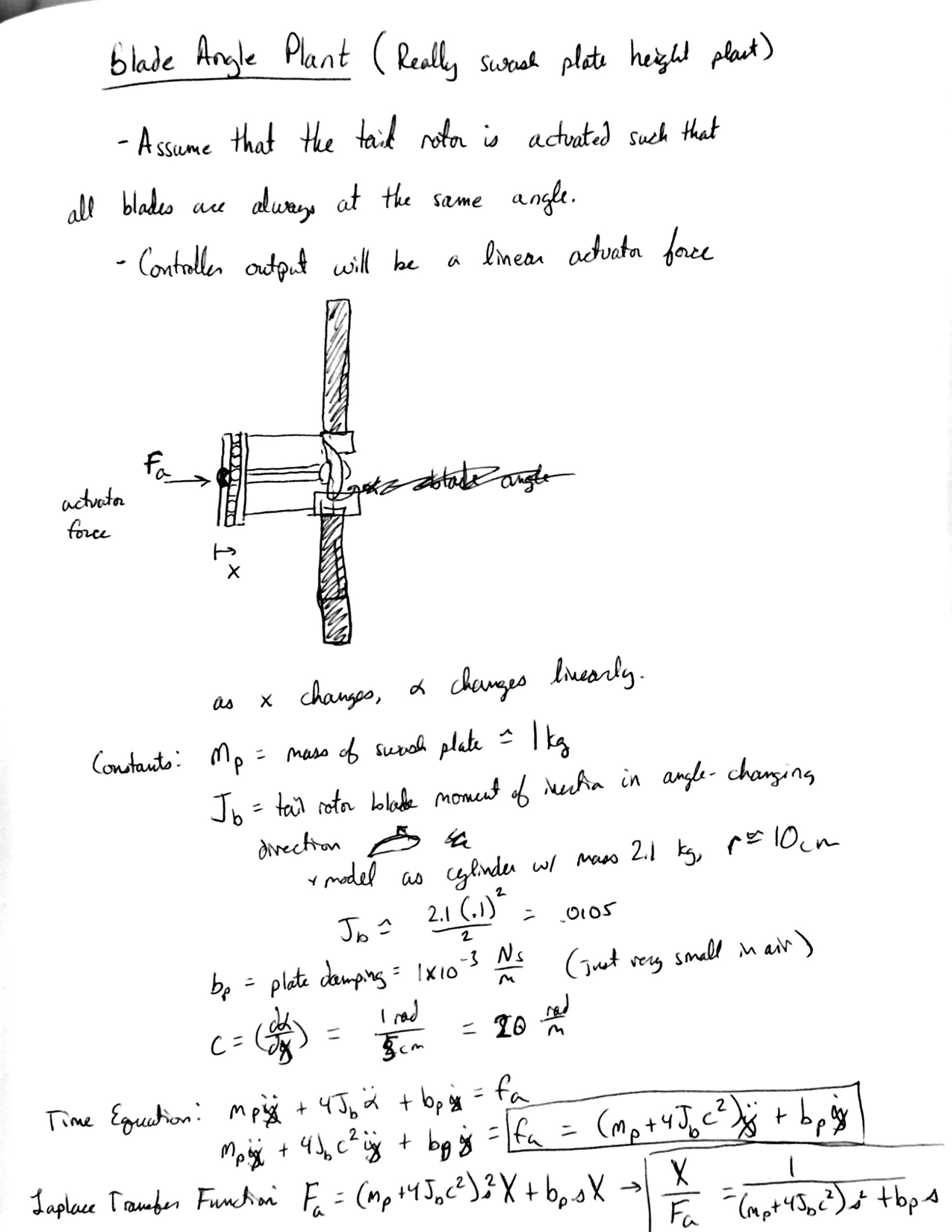
The input to this plant is an actuation force to move the swash plate up/down and the output is the blade angle.
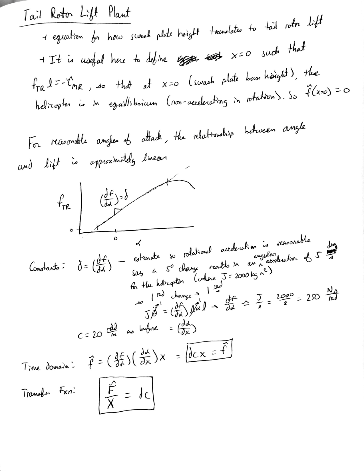
The input to this plant is the angle of the blades and the output is the force that they produce.
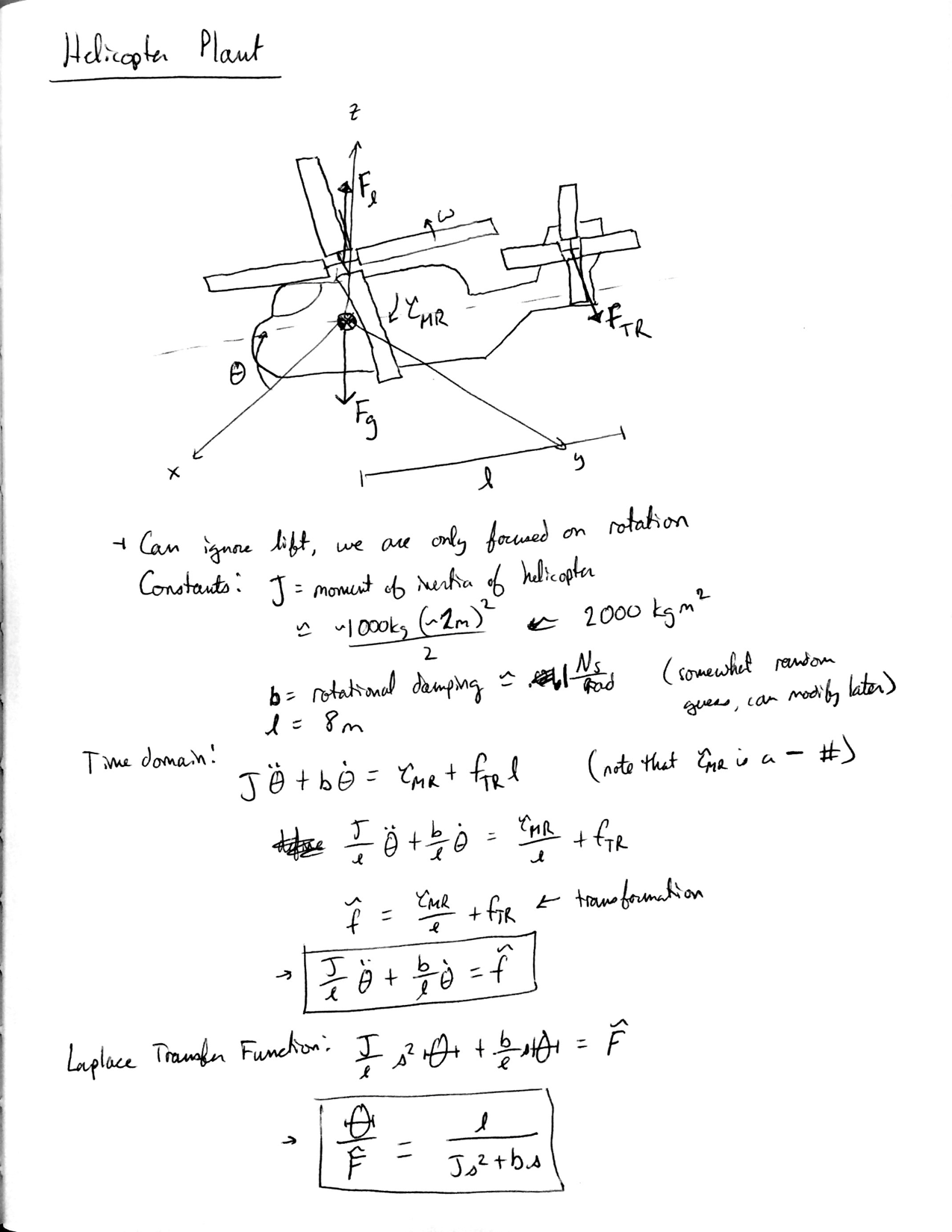
3. Helicopter Plant
The input to the Helicopter Plant is the extra force from changing the angle of the blades and the output is the helicopters angle.
- Block Diagram, Equations of Motion, and Transfer Function

- Calculations and Parameters
- Simulation (Step Response)
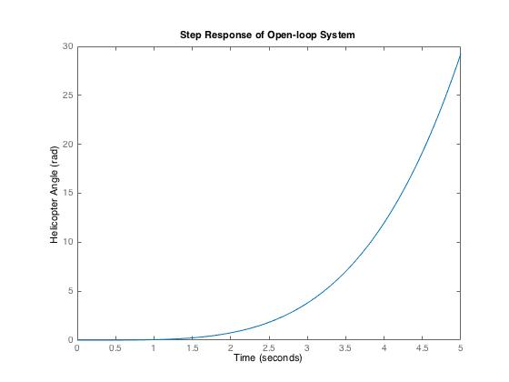
As shown in the figure, the response of the open-loop system to a step input is highly unstable. The "input" that is being modeled here is really the actuator input force to rotate the tail rotor blades. Given a constant force, the angle continues increasing at an accelerating rate - though in reality the blades would both stall and have a mechanical maximum rotation angle, so this model is only valid for a few seconds. Regardless, the response is clearly unsatisfactory and doesn't get to what we really want, which is a specific helicopter angle. Therefore, we will have to implement closed-loop control.
Control Design
- Control Description
There are actually two control loops in our system. The inner loop is the controller for the angle of the blades and the outer loop is the controller for the overall angle of the helicopter. For the inner loop, the plant for the blades has very small damping, and therefore we decided to add a PD controller with a fast pole in order to help damp the step response. For the outer loop, our desired response is for the helicopter to go to the desired angle at a reasonable rate (not exceeding 60˚/s) without actuating the swash plate more than 2.5cm in either direction, which corresponds to the maximum tail rotor angle of attack change of about 30˚ in either direction. For the helicopter plant the damping is also small, so we chose another PD controller (with fast pole) to help damp the system response and get the desired rise time, settling time, and meet the constraints on maximum actuator force, swash plate position, and rotation speed.
- Block Diagram

- Swash Plate Height Controller
For this controller the input is the desired swash plate height (which corresponds to a blade angle) and the output is the actual swash plate height. For the PD controller we set Kd = 1/3*Kp after making a number of root locus plots to find what value of Kd compared to Kp resulted in the best stability. Then we iterated on the gain value based on the root locus, plotting the step response of both the swash plate position and actuator force for a 5cm step and converged on a solution that had the best possible response speed while maintaining a max actuation force under 100N.
- Helicopter Angle Controller
The input to this system is a desired angle and the output is the actual angle of the helicopter. The approach to finding the gains was similar to the swash plate controller. For this controller we once again iterated with root locus on a PD controller with a fast pole - but used an interesting technique that Adam taught us. Since the poles of the inner system (the swash blade actuator) are must faster than that of the outer system, one can design the outer system using all of the techniques we have previously used under the assumption that the inner system has an instantaneous response (i.e. transfer function of 1). We used this method to find the relationship between Kp and Kd, settling on Kd = 9Kp.Once we had this value, we implemented it into the real system and played with the root locus just a little bit more to give us Kd = 8.6Kp. To estimate the max gain this controller we simply plotted the swash plate position as a result of the gain. From looking at the root locus and playing with the gain, we found that K = .0023 is the maximum gain at which both the maximum swashplate actuation and maximum rotation rate constraints are met (a lovely coincidence).
- Final Transfer Function
Theta(s)/ThetaDesired(s) =
                        44.45 s^4 + 1250 s^3 + 1.042e04 s^2 + 2.203e04 s + 2423
  ----------------------------------------------------------------------------------------------------
  s^8 + 38.5 s^7 + 618.6 s^6 + 5680 s^5 + 3.113e04 s^4 + 7.99e04 s^3 + 6.31e04 s^2 + 2.203e04 s + 2423
Attach:ArataGarnier_HelicopterModel.txt
Results
- Simulink Model
Attach:ArataGarnier_SimulinkModel
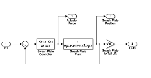
- Helicopter Control System

- Swash Plate Control Subsystem
- Simulations
Step Input (shown in controller design section)
The response of the helicopter to step input meets the desired specifications and constraints, but has some undesirable characteristics. The maximum rotation rate is just under 60˚, as desired, and the swash plate actuation is within desirable limits of +-2.5cm. However, the maximum overshoot is nearly 25%, and settling time is around 21 seconds. Our low estimations of blade-angle-to-lift-force ratio and maximum actuator force result in a system that meets specs, but does so with less-than-optimal time characteristics.
- Ramp Input
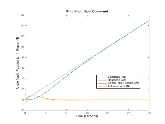
A ramp input into this system is merely the command to spin at a constant rotational rate. Our control system does this quite well, converging on the desired angle after about 15 seconds and following it perfectly from there on. Given the nature of the system, following a ramp input is easy, as only very little force is required to counteract damping once the helicopter is at the correct rotational velocity.
We simulated ramp input by commanding that the helicopter spin at 1/2 radian per second. The graph shown below gives the results. We discovered from this simulation that, while we used a step input of 5cm into the swash plate control subsystem to determine the maximum gain based on 100N max of actuator force, the dynamics of the helicopter system around it are slow enough that no input into the subsystem is ever going to be anything like a step, and thus the actuation forces will be very small (1N at most in this case). The swash plate stays well within its +-2.5cm range.
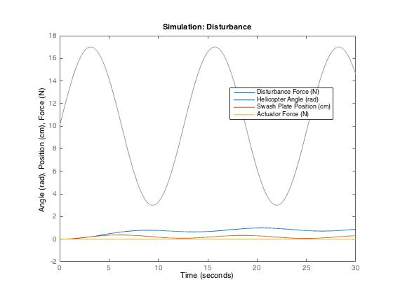
- Disturbance
We modeled the system response to disturbance by inputing a force that varies sinusoidally from 3 to 17N on the tail rotor. This could reasonably be the result of wind causing a greater torque on the tail rotor than on the fuselage. The results of this simulation were, unfortunately, incredibly poor. With an average disturbance force of only 10N, the helicopter ends up with a steady-state error of nearly a radian. In the case of a direction-based disturbance such as wind, the steady-state error would be less (due to the trigonometric drop-off of force), but still far from nominal. This result is likely another function of our low blade-angle-to-lift-force estimate, which forced us to include very low gain in the system.
The transfer function with respect to disturbance is: Theta(s)/W(s) =
          0.004 s^4 + 0.054 s^3 + 0.4994 s^2 + 1.798 s + 1.348
  --------------------------------------------------------------------
  s^6 + 13.5 s^5 + 124.9 s^4 + 449.4 s^3 + 381.6 s^2 + 138.5 s + 15.51
- Noise
The system response to unbiased sensor noise is excellent. This is a result of the generally slow dynamics of the helicopter and control system that we implemented to ensure rotational velocities and accelerations weren't too large. For this simulation, we based random noise with amplitudes from -3˚ to +3˚ on top of a sinusoidal periodic noise with amplitude 3 and a frequency of 10Hz. The effect on the helicopter from such a quick noise signal (even though this is actually incredibly low frequency for real noise) is negligible. The swash plate controller, however, does do a lot of work trying to keep up with the signal, bouncing between +- 5N or so. While this is a waste of energy for the helicopter, it is not at all a dynamic problem, and only changes the swash plate position about a millimeter or so.

The transfer function with respect to noise is merely the negative of the general transfer function for commanded inputs.
- Results
Our control system successfully follows commands and is incredibly robust to sensor noise, but does not fair well against disturbances. This is a result of the necessarily low gain we implemented when designing the controllers for step response characteristics. This general design is better suited to indoor RC helicopters (though the physical parameters would be much smaller) that don't need to be robust to disturbances such as wind (which would just blow them away) than to a large-scale passenger helicopter.
Conclusions
The response of the helicopter to our control system meets the absolute specifications and constraints we gave it in the first place. However, in a real-life application, the step response is rather poor, and the steady-state error with respect to disturbance is absolutely unacceptable. For the step response, a 21 second settling time and 25% overshoot is much higher than anything one would see on a real helicopter. For a disturbance that increases the net force of the tail rotor by an average of only 10N (a pretty weak wind), the steady state error is nearly a radian, which is just a completely different heading than the desired one.
If we were to continue to work on this control design in the future, the first order of business would be to get much more accurate estimates for the amount of force the swash plate actuator can output (if it's hydraulic, for example, the force could be much much higher than our assumed 100N) and the coefficient of proportionality between tail rotor blade angle and tail rotor lift - which is a huge factor in how much force we can produce (max is currently 125N in either direction, which is quite low). We believe we vastly underestimated both of these numbers, which heavily limited our control design and gain values and ultimately gave us a system response that was sub-par. In addition, adding one or more lag compensators to the design could, in theory, increase the low-frequency gain and reduce error as a result of disturbances without heavily affecting the step response - so lag compensation would be our next avenue of control solutions to implement.
Acknowledgments
We would like to thank Adam Leeper for advice in dealing with embedded control loops.
Files
- Design of control system
Attach:ArataGarnier_HelicopterControlModel
- Simulation code
Attach:ArataGarnier_Simulations
- Simulink model of system (not used in simulations)
Attach:ArataGarnier_SimulinkModel
References
Excellent overview of basic Helicopter controls: http://www.pilotfriend.com/training/flight_training/rotary/helis.htm