

Jeff Sarsona Saba Fazeli

Schematic of Electronic Throttle Control
Electronic Throttle Control
Saba Fazeli, Jeff Sarsona
Abstract
For our project, we would like to investigate drive-by-wire systems used in automobiles. We are specifically interested in the possibility of exploring throttle-by-wire systems, and hope to be able to design a controller that controls an input torque (considering a given input angle of the throttle) to give a fast and accurate output angle of the sprung butterfly valve in the throttle body.
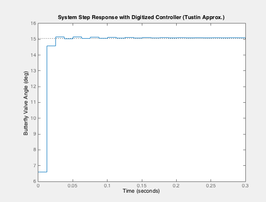
Advanced Feature: Simulink model of the digitized system using the Tustin approximation.
Introduction
We are doing this project because we think it is an approachable design problem directly related to the current trends of automotive innovation--it allows us to practice our controller modeling to replace a previously mechanical system (cable-actuated throttles) with an electronic solution (motors and controllers). Drive-by-wire systems have become increasingly common in almost all vehicular applications (steering, throttle, brakes, shifting, parking), and we thought it would be interesting to pursue one of these to get a sense of how the others are modeled as well. It also helps that we both like cars a great deal, and can talk about what we would expect the system response to look like given our inputs.
Plant Model
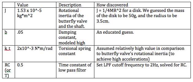
The model of our throttle-by-wire system serves to control a motor torque to map it to a desired position of a butterfly valve in the intake system of an automobile. The valve itself is modeled as a disk on a rod, which is sprung shut (very close to shut, to allow idle; we treat shut as 0deg) by a very stiff torsional spring (with spring constant kt), and actuated by an input torque T from an electric motor. The shaft and motor are coupled in such a way that damping effects are not negligible (this value is modeled conservatively high to model the possibility that the motor-valve interface erodes over time, or that friction is somehow a great issue in the problem). The butterfly valve actuates between 0 and 90 degrees, and needs to be capable of opening and closing quickly to track the driver input closely. The spring is configured to be strong enough to close the valve quickly after the gas pedal is dropped quickly (i.e. input torque becomes zero).
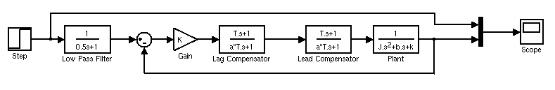
We plan to implement a lead-lag compensator to give us control of the plant, which is shown below. A low pass filter (with a corner frequency of 2Hz), is implemented before the input of the control system to knock out any oscillatory inputs, which internal combustion engines (and passengers) quite dislike.
Derivation, time domain function, and transfer function

Open loop system

Closed loop system with Low-Pass
For our open loop test, the input to the plant is a torque (0.5 N*m, in this case). The output of the open loop plant is the angle of the butterfly valve in the intake manifold. The open loop behavior of the plant shows a huge steady-state error, which isn't exactly the best thing for such a system. The step response shown is to an input of 0.5 N*m.

Unit step response of Open Loop System
Control Design
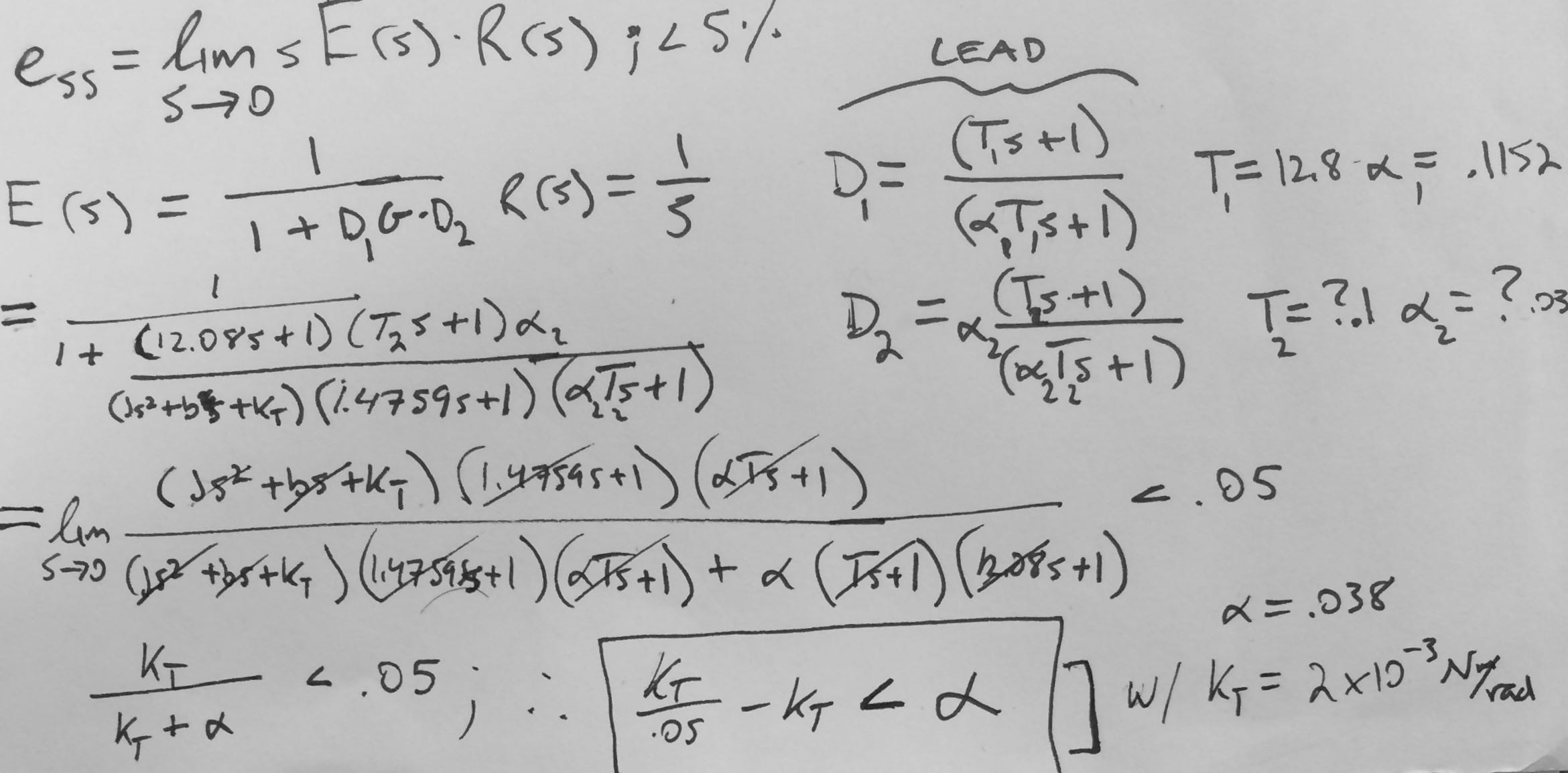
Our control approach was primarily focused on having quick response time, minimal overshoot, and very low steady state error. Our operating frequency is very low (0-1 Hz range), considering the inputs of the driver, so we began by checking the phase margin around those frequencies. The phase margin was very low (~1.5 deg), so we decided to add a lead compensator to raise the phase margin to ~30 deg, making the system more stable around our desired frequency range. Even still, the system response was not nearly stable enough.

Results
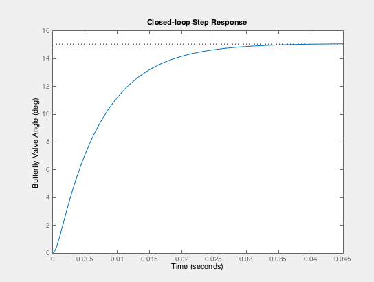
The following step response plot of the closed-loop system for a gas pedal input angle of 15 degrees demonstrates the success of our controller for the given modeled throttle-by-wire system. The output, which represents the butterfly valve angle in response to the input (gas pedal angle) after it passes through our controller, achieves the desired value quickly, with no overshoot, and very little error. Our choice to implement a lead & lag compensator with a low-pass filter proves effective in terms of its speed of response and minimal steady-state error. Another important aspect of the design of the code for the controller (and what allows it to take an input angle and control the torque to hold the valve at that target angle) is the method of calibration that we implemented while testing the closed loop system response. We modulated the values of the input torque (the value of the step response) until we managed to get the system to hold an output angle of 90deg (fully open). From that data point, it was assumed that the electric motor would be capable of providing an input torque linearly from 0N*m to the maximum value calculated (1.59 N*m), and thus a simple gain conversion between input angle and torque was generated (and works rather well!).
DIgitization
In order to digitize our control system, we needed to convert the continuous controller to a discrete controller by z-transformation. This was accomplished by using the Tustin Approximation in Matlab. Our discrete step response matched the continuous response with a bandwidth of 20 rad/s, found by playing with bandwidth values in the Matlab code, which resulted in a sample time of approx. 0.012566 seconds. There is a very slight steady state error, which is due to the use of the Tustin approximation. The discretized controller is shown below, as well as its response to a 15deg step input (the equivalent of a 15deg accelerator pedal compression), which shows its behavior as compared to the s-domain response.

Conclusions
We found that (as shown in the results) that our lead-lag compensator combination did a great job of giving us the critically damped, very fast response we were looking for. In the context of our application, the response we managed to get from the system is remarkably good.
What was surprising, however, was that the addition of the low-pass filter to the system drastically decreased the speed of response of our controller (it increased response time by ~1.7s). This is not beneficial to us, and so we decided to not include the low-pass filter in our final system design. We justified this action by recognizing that the lead compensator effectively acts as a low pass filter for our desired frequency range, and the response of the system is much improved.
The most pertinent aspects of this controller design, it seems, are the physical parameters of the throttle actuator itself (spring constant, mass and rotational inertia, damping), and though we estimated each, slight differences would ultimately change the controller's parameters. If we had more time to work on this, we would expand the analysis to include a DC (or stepper) motor and a position sensor (or encoder). We would also like to try to build a version of the system to see how well the overall control approach works with different system parameters.
Files
Matlab closed loop control of system
References
http://research.ijcaonline.org/volume59/number15/pxc3884273.pdf