

Katie Torigoe Jesus Loza

Commercial aircraft are part of our everyday lives, but we often
forget about the systems that make them so passenger-friendly.
Temperature Control
Project team members: Jesus Loza, Katie Torigoe
Abstract
The environmental control system (ECS) of an airplane is essential to the safety of its passengers. At cruising altitude, air temperature is about -44.35�C -- without a temperature control system, the aircraft's interior would quickly fall below freezing temperatures. In commercial airplanes, passenger comfort is also a priority, making a highly responsive temperature control system desirable. Our goal is to control cabin air temperature to within acceptable industry standards to make the flying experience as comfortable as possible. We show that given a desired temperature and cruise altitude, we can tune our controller to stabilize the cabin temperature in under a minute with time delay accounted for. This simplified model would be a good starting point for creating a more advanced thermal model in which disturbances such as external flow losses could be examined.
Advanced Feature: Our model will implement time delay.
Introduction
Although humans have the ability to detect a wide range of temperatures, comfort can vary greatly within the span of a few degrees Celsius. The industry standard for air temperature varies but most institutions, such as the West Midlands Public Health Observatory, agree that a comfortable room temperature should be between 18�C-21�C. This issue can be even more important in settings like airplanes which are confined places that already tend to lead to uncomfortable experiences. The airplane example is further complicated by the constant change of ambient temperature that is seen with varying altitude. Our control design goal is to be able to adequately control cabin temperature within the comfortable room temperature standards in spite of the outside temperature disturbances seen at a cruising altitude of 30,000 ft.
Plant Model
[Due 3/4:] Describe your plant model.
- Model Description
- Time-domain equation of motion for model and Laplace-domain transfer function for the model.

- Open loop system

- Model Parameters
- Open Loop Simulation

Control Design
Control Approach
For our temperature control system, we can model our airplane as a cylindrical tube of air in an environment that changes temperature. The airplane cabin should maintain a carefully controlled environment in order to facilitate the comfort of its passengers - thus our temperature control system needs to be finely tuned to respond quickly to the changing environment without overshooting the cabin temperature in either direction.
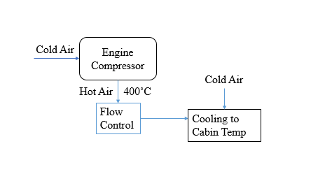
The temperature controller of a typical airplane cabin is seen in the diagram below. The Aircraft Environmental Control System (ECS) bleeds air from the engine compressors to the flow control valve. Temperatures exiting the engine compressor are actually in the regime of 400 degrees Fahrenheit, but our model currently directly controls temperature. (In the next iteration, we should consider that what we actually control in real life is the mixture ratio of air (exterior + compressor) to create a system temperature)
Controlling the aircraft's temperature fits the PD controller's effects. Combining proportional and derivative control allows us to closely control our system's performance criteria and achieve rapid stability. For more fine tuning, integral control would be useful, but our current system has negligible error. While we could apply an integral control now to anticipate error in a future, more complex system, we are leaving it out in order to avoid any possibility of integral windup.
Mathematical Description
For temperature control in a "comfort" zone for passengers, we want minimal overshoot and error. The open loop system appears to be critically damped but has a very long response time. Our PD controller needs to reduce the response time without upsetting the stability or causing overshoot to the system.
This system should be capable of compensating for a steady temperature loss that would come from the altitude change between take-off and cruise. For an average time to reach altitude being about 25 minutes, we calculate that an airplane will rise about 6.096 m/s. Likewise, we calculate the exterior temperature change per second during ascent as -0.0396 degrees C / s. To keep cabin temperature within 2 degrees C of the desired optimum, the rise time should be less than 50 s. For our model, we decided to implement a time constant Tc of 30 s.
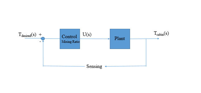
Block Diagram of the CL System
Control Parameter Derivation
By using a PD control system, we assume that our equation will take the classic PD controller form:
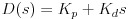
To tune the parameters, I calculated the closed loop transfer function and set its characteristic equation equal to the standard second-order system polynomial:
Closed-Loop Transfer Function:

Characteristic equation and second-order system polynomial equivalence:

I then solved the system using our desired zeta of 1 and wn of 0.06 s (for a rise time of 30 s). This gave us an unexpected and undesirable result, returning Kp = -1 and Kd = -30:

To examine how changing the system parameters would affect the response, I set up a Simulink model. I then adjusted the parameters until I found a set that returned a stable, responsive output. The controller's chosen parameters Kp = 99 and Kd = 0.05 returned the stable Simulink output to a step input of 19.5:

Results
From the input Kp and Kd, our controller returns a stable response that appears to be critically damped with a very quick response time. The system input is the desired temperature of 19.5 degrees C and the steady-state value of the closed loop system is 19.3 degrees. This error is small enough to be negligible, as airline standards give acceptable cabin temperature as 18-21 degrees C.

Closer examination of the system by solving for zeta and wn from the found values of Kp and Kd reveals an interesting trait that goes beyond our intuition: the system remains unstable, with significant undershoot, for zeta < 1.5. This means that in implementation, our system would actually be significantly over-damped. The values of Kp and Kd that work to stabilize the response correspond in our equations to zeta = 1.5 and wn = 10.
Ordinarily, we would not expect to implement an over-damped system, and we would expect that the system would be able to stabilize for slower response times. However, it doesn't negatively affect our system to rise to steady-state faster than our original desire and the system outputs a stable steady-state cabin temperature.
Conclusions
In this project we set out to control temperature within an airplane cabin. We derived our equations of motion from a simplified mathematical model, accounting for time delay in the process. We approximated the time delay using a (1,1) Pade approximation. Putting a unit step input into our open loop system we saw that although our system was stable, it had a very large rise time of over 65 seconds. After some iterations using a PD controller and unity feedback we were able to run a step input of 19.5 (our desired cabin temperature in Celsius) through our updated system and saw that the rise time was now on the order of 1 second. Although our closed-looped system did have a slight steady state error, the desired input was 19.5 degrees C and the steady state output was 19.3 degrees C, the output is still within the accepted industry standard of 18-21 degrees C which means that our result is satisfactory in this application. For future work we would work on adding a ramp disturbance that adequately models the changing exterior temperature as the airplane rises in altitude. We would also want to add a lag compensator to eliminate the present steady state error.
Acknowledgments
Special thanks to Tania for all of her help during office hours this quarter and for project feedback!
Files
1. PD Controller Step Response in Matlab: https://www.dropbox.com/s/tlapsrt3l90asgx/Project_PDcontrol.m?dl=0
2. Simulink Model of Closed Loop Response: https://www.dropbox.com/s/8iuiatjuk5gwpdu/Project_PID_Control.mdl?dl=0
3. Open Loop Step Response in Matlab: https://www.dropbox.com/s/cf48tb39na6xyz4/ENGR105_Project_OpenLoop.m?dl=0
References
1. Equations for calculation of temperature at altitude: https://spaceflightsystems.grc.nasa.gov/education/rocket/atmosmet.html
2. FPE Section 4.3.6: Ziegler-Nichols Tuning of the PID Controller
3. PID Application for a temperature control system: http://www.lakeshore.com/Documents/LSTC_appendixF_l.pdf
4. Mathematical Model for equations of motion http://home.hit.no/~hansha/documents/lab/Lab%20Work/Air%20Heater%20Control%20System/Air%20Heater%20Control%20System.pdf
5. General system research on past work http://www.wseas.org/multimedia/journals/control/2014/a125703-288.pdf http://web.itu.edu.tr/yildiri1/fa11ee432/exp6.pdf http://techteach.no/simview/temp_control/index.php