

TJ Melanson William Mac Farlane

Caption:
Raytheon XOS-2
exoskeleton, 2010.
Raytheon - esque Load-Bearing Arm
Project team member(s): TJ Melanson, William MacFarlane
Abstract
[Due 3/2, 3/4, 3/7, 3/11:] The goal of this is to design and simulate (via Simulink) a load-bearing joint similar to one on the Raytheon XOS-2. Specifically, it would take the place of the elbow link and forearm joint, bearing a load at the end of the forearm or wrist. Given a desired position, it could accelerate and hold the position, even when offset by outside forces; exoskeletons such as the XOS 2 can still bear load even when the user stumbles. Because of this, a quick transient response (such as low settling time and mildly low overshoot) has more importance than the steady-state error. The goal of an arm is not to reach a specific desired angle, but to imitate and amplify a general arm movement. We say the settling time should be within 1 second, and an overshoot of no more than 25% (in case the arm goes past its joint limits). Additionally, the gains must be set to reasonable values (Ki, Kp, Kr < 1000), as this needs to be implementable in a real, physical system. For this experiment, we tested the effect of a 30 kg weight at the end of a 5 kg arm. In order to properly gauge the nonlinear state for large angles, we linearized the equation to both its vertical and horizontal components. Although the XOS 2 has a longer, heavier arm and can bear over 60 kg of weight, this is both with the aid of an entire body and the human. [Due 3/2:] Advanced Feature: We will use simulink to model the non-linear system.
Introduction
[Due 3/2:] Off and on the battlefield, the average military support personnel is expected to lift about 16,000 lb a day. Such continuous strain, over a long period of time, can cause long-term orthopedic damage. As a solution to the load-bearing problem, several companies and organizations have developed robotic exoskeletons to combat this strain. For example, in 2010, Raytheon developed a hydraulic exoskeleton, the XOS series, that allowed a user to pick up 200 lb of material with almost no effort.
Plant Model
[Due 3/4:] Describe your plant model.
- First, describe the model in words.
We are building hydraulic control of a robotic joint with an external load. First, we have the torque driving the link. This is created by the hydraulic system, and is directly proportional to the input force (according to Pascal's principle), and will be considered an upward force. Additionally, there is the weight of the load at the end. For the intent of this equation, we consider the weight of the arm as well as the weight of an external mass picked up by the hand (at the end of the arm). This weight of the load will be equal to the weight of the object (in N) multiplied by the length of the forearm perpendicular to gravity as well as the weight of the forearm multiplied by half the length of the forearm perpendicular to gravity (assuming equal mass distribution in the forearm), and is pointed downward. In addition, the robot will have some form of friction, which is directly proportional to the angular velocity of the joint and opposes angular motion. Finally, the final acceleration is the total sum of these components (with their directions) divided by the inertia of the system. For now, we consider the link to be a cylinder, with the rotational axis at the center of one of the cylinder's bases.
- Second, give the time-domain equation of motion for the model and (if possible) the Laplace-domain transfer function for the model.


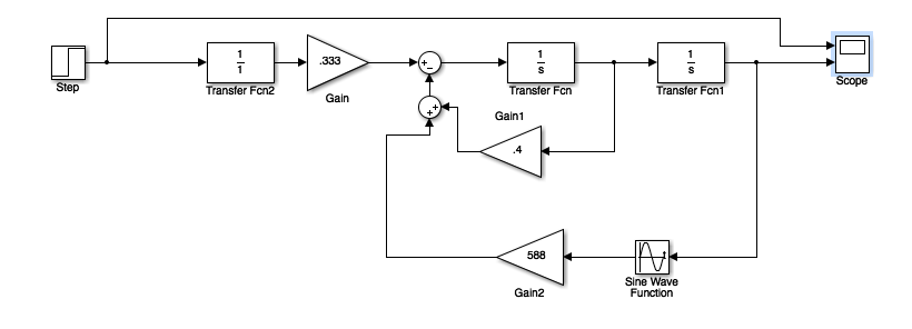
- Third, show a block diagram of the open-loop system.
- Fourth, show the derivation of your model as inline equations, as inline images, or in an attached file.

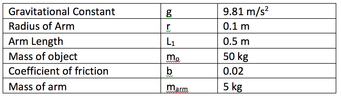
- Fifth, give a list of parameters of your model, what values you are using for those parameters, and how you found/estimated them.
The inertia depends on the mass of the arm, its radius, and its length. The hydraulic torque, T, is a part of the system and is the input to the plant. L1gsin(theta)(m +m_arm/2) is the gravitational term, where m is the extra object mass, m_arm is the mass of the forearm, g is the gravitational constant, L1 is the length of the forearm, and theta is an input. b is the coefficient of friction, which varies greatly and depends on the material used. We have estimated b, but that is very hard to do without actually performing an experiment.
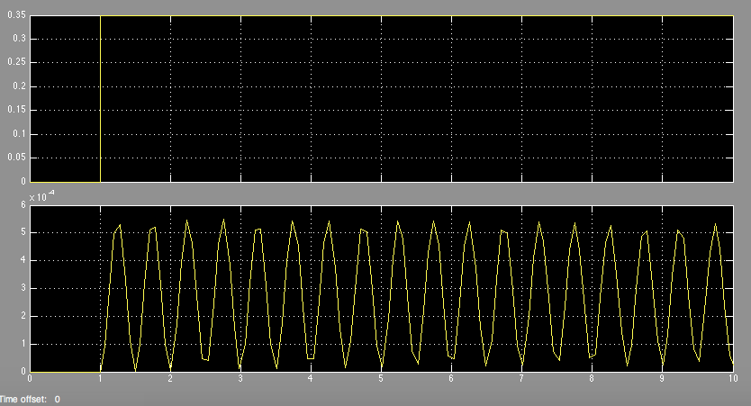
6 - Initial Simulation
We did an initial simulink simulation for the open loop nonlinear system. The open loop simulation scope output is shown below (based on the open loop block diagram shown above). What we see is that the output is largely underdamped and does not end up anywhere close to the desired output angle (it basically remains at 0 degrees).
Expected length: Approximately 1-2 "pages" if this were on 8.5" x 11" paper.
Control Design
[Due 3/7:] Give your control design approach. First, describe the control approach in words.
The model is a PID controller, which minimizes the effect of error in a system while allowing fast compensation for large disturbances in force. Whether the robot is slightly off its desired position does not matter as much as how it responds if the user, for example, stumbles, or an extra weight is added to the system.
It is also important to describe the specifications of our controller / what constitutes success. Given that this exoskeleton arm is designed to be on a real human's arm, we based the specification off of how we would expect a normal human arm to behave. This led us to specify that our settling time must be less than 1 (it shouldn't take you a long time to move your arm in one degree of freedom) and our maximum overshoot less than 25% (it isn't good for human joints to be overshooting because it could lead to hyperextending). Moreover, this exoskeleton is meant to make it much easier to lift heavy weights. As a result, we specified that our steady state error should be less than 5%. This means that the human will only have to account for 5% of the weight that he or she is lifting - the exoskeleton takes care of the rest. Finally, the exoskeleton must be able to lift external masses of up to 30 kg.
- Second, give an appropriate mathematical description of your controller.
In order to design the PID controller, we first linearized around a theta of 0 (where the gravity term was approximately a constant) and found the closed loop transfer function for the linearized system.

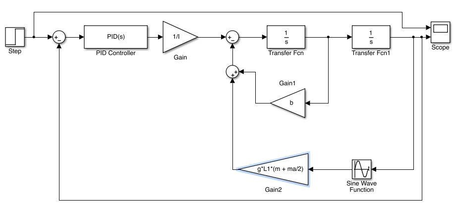
- Third, show a detailed block diagram of the closed-loop system, with signals and blocks clearly labeled.
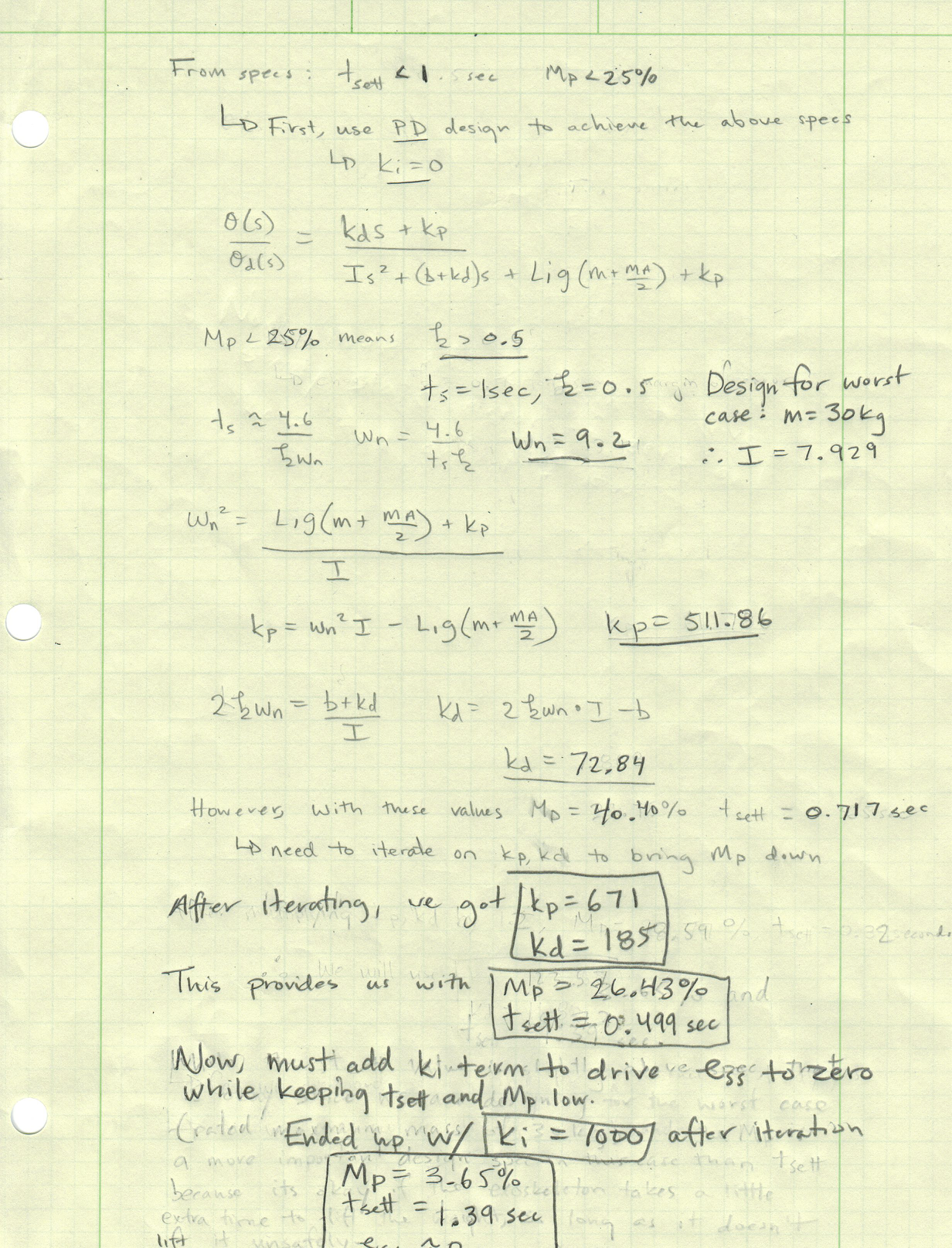
- Fourth, explain the derivation of your controller parameters and (if appropriate) the evolution of your controller through the design process. Include information as inline equations, as inline images, or in an attached file.
We first started by designing a PD controller to satisfy the specifications that the settling time be less than 1 second and the maximum overshoot be less than 25%. These specifications provided us with approximate values for the natural frequency and zeta. We then found the kp and kd values from the characteristic equation. As those values are just estimates, we iterated on those until we achieved met specifications. We did this initial controller design with the condition that there is a 30 kg mass at the end of the arm. This ensures that the system will be able to handle any disturbance (picking up of a mass) less than 30 kg and still meet specifications.
Next, we introduced an integral control term to eliminate the steady state error, while maintaining the settling time and maximum overshoot specifications. This was important because the closed loop system with a PID controller is type 1 with respect to disturbance, meaning that the steady state error will go to zero for a step input, whereas the closed loop system is type 0 with respect to disturbance using only a PD controller.
Expected length: Approximately 1-2 "pages" if this were on 8.5" x 11" paper.
Results
[Due 3/11:] Provide the results of simulations or experiments that clearly show the closed-loop system behavior. Clearly describe the input and output signals.
Below we show the system results for two cases: when there is no mass picked up at the end of the arm and when there is a 30 kg mass (the maximum rated weight of our exoskeleton) picked up at the end of the arm. We show both the linearized and non-linear results below. We show the 30 kg case because as we state in the abstract, the goal of the exoskeleton is not to achieve a desired angle, but to be able to assist with weight bearing. Thus, the 30 kg cases show the system response to a disturbance to simulate how well the exoskeleton can assist with weight bearing.
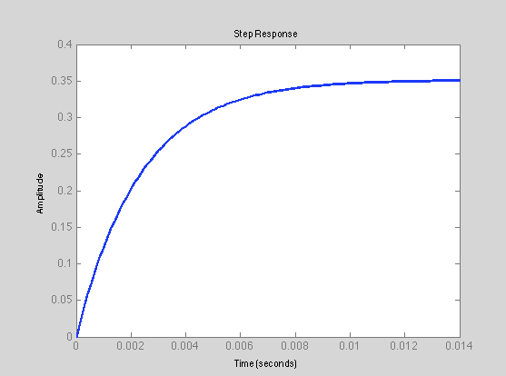
Below is the step response to an angular input of 20 degrees when there is no mass at the end of the arm for the linearized model:
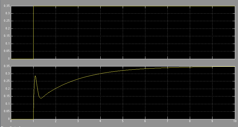
Below is the step response to an angular input of 20 degrees when there is a 30kg mass at the end of the arm for the linearized model:

Below is the simulink non-linear model response for a step input of 20 degrees (0.349 radians) when there is no mass at the end of the arm.

Below is the simulink non-linear model response for a step input of 20 degrees (0.349 radians) when there is a mass of 30 kg at the end of the arm.
Below is the summary of our results:

Expected length: Approximately 1 "page" if this were on 8.5" x 11" paper.
Conclusions
[Due 3/11:] Describe the overall results of your experiment/simulation. Is the system response satisfactory in the context of the application? What would you do in future work if you had more time to work on this? Expected length: 1 paragraph.
The system response is satisfactory in both the linearized and non-linear contexts. First, in the linearized case with no mass at the end of the arm, the system response is excellent in terms of settling time, maximum overshoot, and steady state error. Second, for the linearized case with a 30 kg mass at the end of the arm, the system response is excellent in terms of maximum overshoot and steady state error. While the response is slightly out of specification with regards to the settling time (1.40 > 1), this is okay in the context of the application. It is okay if it takes a little bit longer for an exoskeleton to lift a heavy weight, so long as it does it safely (no large overshoot) and accurately (small steady state error), which it does. Third, in the non-linear case with no mass at the end of the arm, the system response is again excellent in terms of settling time, maximum overshoot, and steady state error. Finally, in the non-linear case with a 30 kg mass at the end of the arm, the settling time is again the only quantity out of specification. While this isn't ideal, we are okay with it given the constraints on designing a controller for a non-linear system and because it is not a safety hazard or accuracy issue (as stated previously).
The one thing that isn't ideal is that the k values are quite large (and perhaps impractical). If we had more time to work on this, we would want to take into account the entire exoskeleton body, as opposed to just the arm. We think this would have a significant impact on the value of the moment of inertia, which in turn would greatly affect our k values (hopefully bringing them down to more practical values).
Acknowledgments
We would like to thank Allison and Tania for their help on defining goals and helping with the optimization process during office hours.
Here you can list any individuals or groups who helped you with your project. This is optional, so delete this section if you aren't using it. Expected length: 1-2 sentences.
Files
Code and Simulink models should be linked here. You can upload these using the Attach command.
- Attach:MelansonMacFarlane_SineCode - Matlab code for the vertical response
References
http://www.army-technology.com/projects/raytheon-xos-2-exoskeleton-us/
Wiki examples
Here is how to link to a file (note that you may need to compress/zip your code and CAD files into zip files so that that wiki will let you upload them, due to file type restrictions): Attach:HapkitTest.ino.zip
Here is how to add an image: 
Here is how to attach an image with the height adjusted (to 100 pixels)
Here is how to attach an image with the width adjusted (to 200 pixels)
Here is how to link a youtube video: