

Xinyue Liu Zihui Liu

Caption: Gondola lift is a common cable transport which is supported
and propelled by cables from above.
Gondola lift angle control
Project team member(s): Xinyue Liu, Zihui Liu
Abstract
Gondola lift can be seen in various places, especially at tourist spots. Taking a gondola lift, we can safely get from one station to another and enjoy beautiful scenery from high above. In this project, our team analyze how to control the gondola lift downright (angle = 0) when moving the carrier grip. Specifically, given a step input we want to stabilize the closed-loop system with no more than 25% overshoot, less than 3s settling time and less than 5% steady-state error. We model the plant as a pendulum mounted to a horizontally moving block, simulate the nonlinear system in Simulink, and analyze the approximate linearized system as comparison. For the controller, we first design linear system controller (PID, PD+lag compensator) to meet the spec, then design the nonlinear one based on it. Our final step response of the closed-loop linear system using either PID or PD plus a lag compensator meets our design specification. However, for the closed-loop nonlinear system, the response of a unit step input are not in our desired range even though we are able to stabilize the system by tuning controller parameters. We also investigate the relationship between linear and nonlinear systems based on our results, and analyze when the linearized system can be a good approximation of the nonlinear system.
Advanced Feature:
(1) Simulink model of the nonlinear system.
(2) A closed-loop system transfer function of order 4 or higher.
Introduction
Gondola lift is a commonly used passenger lift in many places such as parks, ski areas and resorts. It is propelled by cables from above to transport tourists between two stations. As the grip sliding on the supporting cables, the gondola may swing back and forth due to the propelling force. The swing angle is typically within the safe region which is 15 degree each side according to Diversified Certification & Inspection Services Inc.(2013)[1]. However, without external control it is hard to keep the angle of gondola within a small range, let along to reach the perpendicular steady state. In order to provide passengers with safe and comfortable experience, a reliable control system is required to prevent the gondola from oscillation during moving. How to design a control system to quickly stabilize the lift becomes an interesting topic. The goal of our team is to design a control module which can keep the gondola straight down to provide tourists with safe transport.
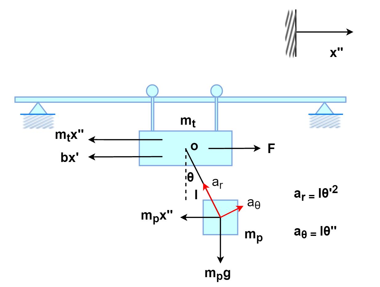
Plant Model
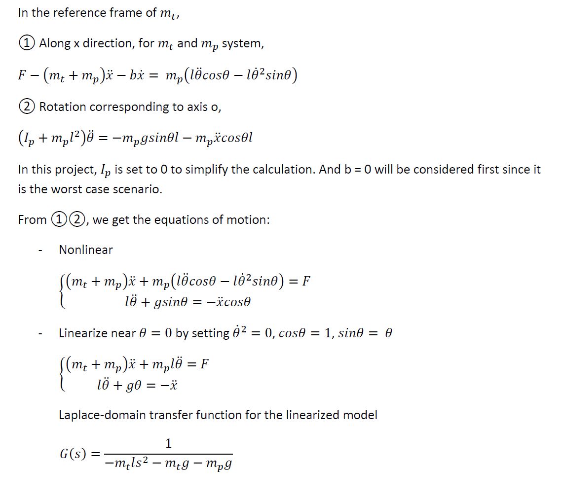
1. We use a rotational and translational model to investigate the system. The carrier grip is modeled as a moving block with mass mt, while the gondola is modeled as a pendulum swinging along the x direction with mass mp and angle θ. The gondola arm has length l and a negligible mass.
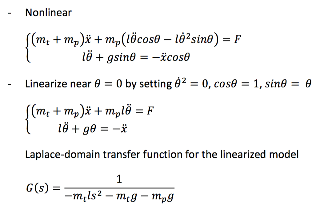
2. The time-domain equations of motion for both the nonlinear and the linearized model, and Laplace-domain transfer function for the linearized model
3. The block diagram of the open-loop plant G(s)
Nonlinear model, simulink block diagram of G(s)

4. Derivation of our model
5. Model parameters
In our model, there are three parameters to estimate, mp, l and mt. mp is the total mass of gondola plus the mass of all passengers. The mass of gondola lift is approximate � of a standard car. According to Hypertextbook(2000)[2], A car's mass may vary in the range of 990 to 2000kg. So we choose the maximum mass and then time the factor � to get 500kg for the gondola lift. Since our team mainly focuses on the gondola lift with a maximum of 4 people, we set a maximum of 150kg per passenger due to safety consideration, 600kg in total . According to the design specification from Beautiful Vancouver website(2016)[3], we estimate the length of the gondola arm l to be 2m and our estimation of the grip is approximate 100kg.
6. Results for the open-loop behavior of the plant
We apply a step reference to the plant and get an output of the swing angle w.r.t the vertical line.
(1) For the nonlinear open-loop system (G), we simulated a step response of the plant from the Simulink.

(2) For the linearized open-loop system (G), we plot the root locus and step response in MATLAB to compare with the nonlinear case.

The step response are very similar for the two cases. We observe an oscillating (non-decay) response with an amplitude of around 16x10-5. The root locus plot shows that the open-loop system is marginally stable at gain K<1.2x10⁴, for the other K the system is unstable.
The open-loop system response does not decay as time increases, which implies that the gondola will swing back and forth forever. We want the gondola to quickly reach steady state.
Control Design
1. Control approach
Our overall approach is to design a controller to stabilize the linearized system in 3s with less than 5% steady state error for a unit step input, then design the nonlinear system controller based on the linear one. To find a desired linear system controller, we tried two methods. First is to use a PID controller. Since a proportional controller cannot stabilize the closed-loop system, and a PD controller can stabilize the system but will leave a steady-state error, we then choose a PID controller. Our second method is to use a PD controller plus a lag compensator.
2. Mathematical description of the controller
(1) For the linearized system:
- PID controller, D(s)=Kp + s*Kd + Ki/s,
where Kp = 10000, Kd = 2000, Ki = 50000.
- PD controller plus a lag compensator, D(s)=DPD * Dlag,
where DPD = Kp + s*Kd = 10000+2000s, Dlag (s) = 116.5 * (0.1s+1) / (11.9s+1).
(2) For the nonlinear system:
We choose the PD controller (adding a fast pole) plus a lag compensator, D(s)=DPD * Dlag,
where DPD = (1000s+100)/(0.01s+1), Dlag (s) = 116.5 * (0.1s+1) / (11.9s+1).
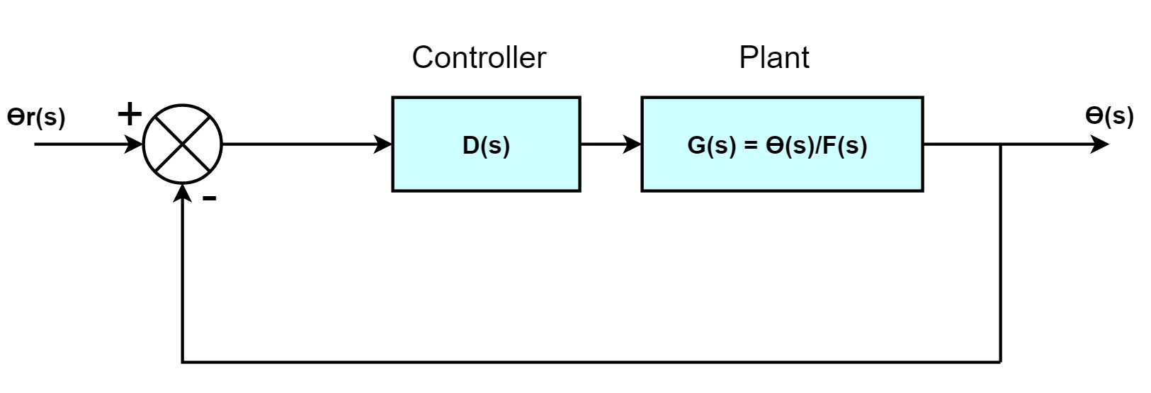
3. Detailed block diagram of the closed-loop system
(1) Overall block diagram of the closed-loop system
(2) Simulink block diagram of the nonlinear closed-loop system

4. Derivation of controller parameters and the design process
Since our plant G(s) has a negative sign in the front, we change our sign convention of the angle θ towards the opposite direction, so that G(s)=1/(200s2+11772) has a positive sign. Then we design a PD controller that can stabilize the linearized system in 3s. Based on the parameters of the PD controller, we find the desired PID and additional lag compensator that can reduce the steady state error. The detailed derivations are attached.

Results
Input signal: a unit step reference
Output signal: swing angle
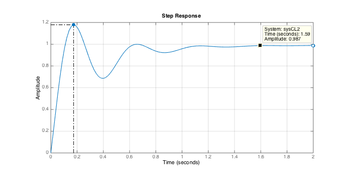
(1) For the linearized system, a unit step response for the closed-loop system
- Using the PID controller D(s)=10000 + 2000s + 50000/s

Rise time 0.17s, settling time 1.4s, maximum overshoot 0%, steady-state error 0.1%
- Using the PD controller plus a lag compensator D(s) = (10000+2000s) * 116.5(0.1s+1)/(11.9s+1)
Rise time 0.08s, settling time 1.0s, maximum overshoot 19%, steady-state error 1%
(2) For the nonlinear system, a unit step response (in the simulink scope) for the closed-loop system using
D(s) = (1000s+100)/(0.01s+1) * 116.5(0.1s+1)/(11.9s+1)

The results of a unit step response show that the linear system behavior meets our design spec (overshoot <= 25%, settling time < 3s, steady state error<5%). However, for the nonlinear case given a unit step input, we can only stabilize the system with our selected controller parameters. Since the nonlinear system behaves differently for relatively large θ (a unit step is already very large in our case), it's hard to find a group of controller parameters that can meet the design spec.
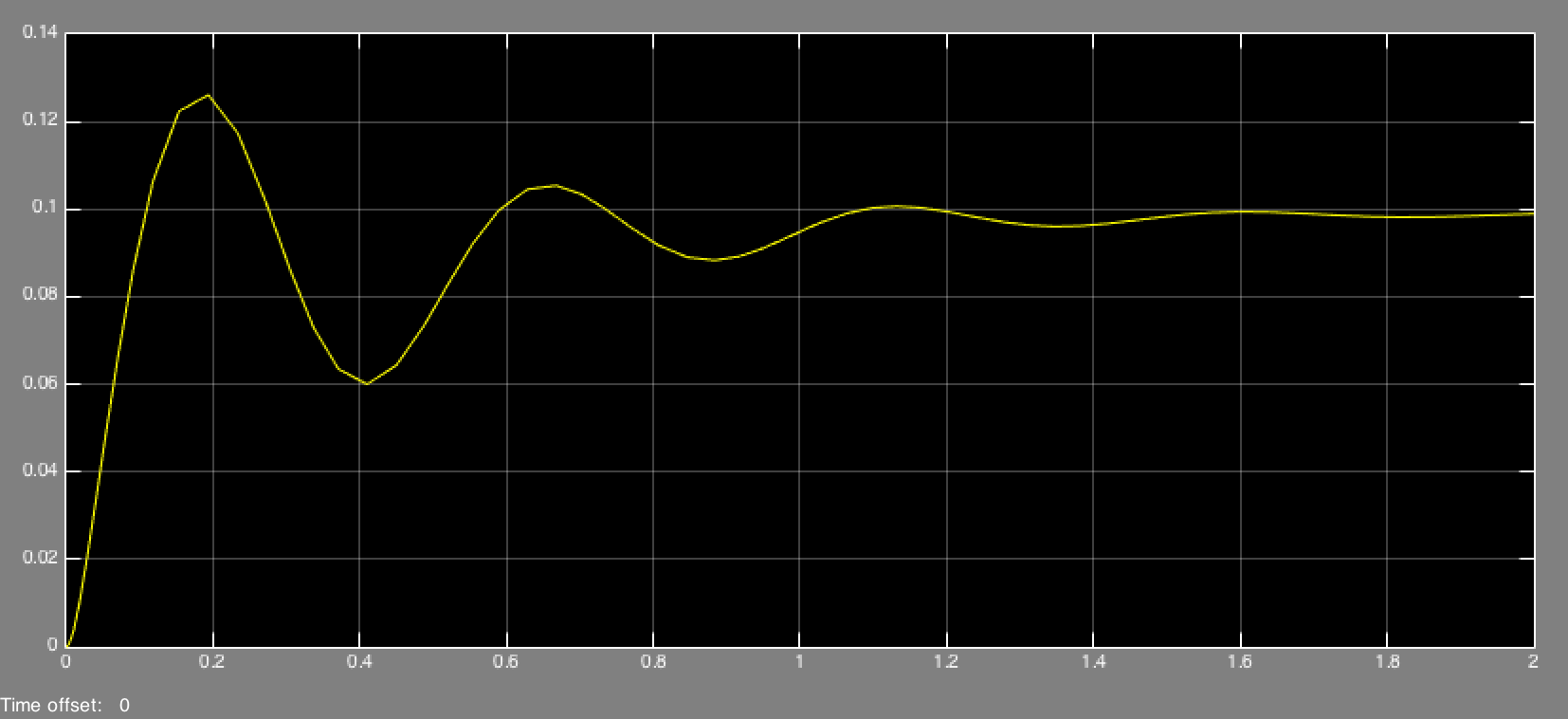
To get a better idea about the relationship between the nonlinear system and its linearized approximation, we simulate the behavior of both systems under 0.1 unit step input using a controller D(s) = (2000s+10000)/(0.01s+1) * 116.5(0.1s+1)/(11.9s+1). The following results indicate that as long as θ is very small (in our case < 0.3 based on the simulation in Simulink), the linearized system is a good approximation of the nonlinear system.
- linearized system, 0.1 unit step response

- nonlinear system, 0.1 unit step response
Conclusions
For the overall results of experiment and simulation, our linearized system in two cases (PID controller and PD controller plus a lag compensator) perfectly meets our design specification (overshoot <= 25%, settling time < 3s, steady state error<5%). Our final step response of the closed-loop linear system using PID controller has a rise time of 0.17s, settling time of 1.4s, maximum overshoot of 0%, and a steady-state error of 0.1%. Using PD controller plus a lag compensator, the system has a rise time of 0.08s, settling time of 1.0s, maximum overshoot of 19%, and a steady-state error of 1%. For the nonlinear system, the system only behaves similar to the linear system and meets the specification as step reference θ is small. When θ is relatively large (around 1), the nonlinear system can be stabilized but the overshoot, settling time and steady state error are not in our desired range. We find that the control techniques that we obtained from this class may not be enough when dealing with nonlinear systems. Other advanced techniques are needed in order to make the nonlinear system meet our specification. If we have more time to work on this project, we can do more investigation on the nonlinear system. We could also add a damping term for θ in the dynamic model to see how the damping would influence the control efforts.
Acknowledgments
Thanks for Professor Allison Okamura who helped us review our project and provided helpful suggestions for the improvement.
Files
Code and Simulink models:
- Matlab Code: Attach:Project_Code
- Simulink model of the linear open-loop control system with PID controller: Attach:simulink_linear_PID_OL.zip
- Simulink model of the linear closed-loop control system with PID controller: Attach:simulink_linear_PID_CL.zip
- Simulink model of the linear open-loop control system with PD controller plus a lag compensator: Attach:simulink_linear_PD_Lag_OL.zip
- Simulink model of the linear closed-loop control system with PD controller plus a lag compensator: Attach:simulink_linear_PD_Lag_CL.zip
- Simulink model of the nonlinear plant: Attach:simulink_nonlinear_plant.zip
- Simulink model of the nonlinear closed-loop control system: Attach:simulink_nonlinear_CL.zip
References
[1] Diversified Certification & Inspection Services inc.(2013). Permanent Engineered Horizontal Lifelines. Retrieved from http://www.dcis.ca/angle_degree_calculator_fall_arrest_protection.htm
[2] Elert. G(2013). Mass of a Car. Retrieved from http://hypertextbook.com/facts/2000/YanaZorina.shtml
[3] Beautiful Vancouver(2016). Whistler PEAK 2 PEAK Gondola. Retrieved from http://petersvancouver.blogspot.com/2013/06/peak-to-peak-whistler.html