

Camille Dustin Montse

Caption:
Finalized Braille Display during the Open House
The Braille Display
Project team member(s): Camille Townshend, Dustin Dienhart, and Montserrat Cordero
On this page... (hide)
Introduction
When we were presented with the task of designing and building a haptic device the first thing that went through our minds was relevance. How could we build a project that could be relevant for someone? How could we change lives through haptics? Naturally, when you think of common applications of touch in the world, one of the first things that comes to mind is braille: reading through touch. We set out to develop a compact way to display the braille alphabet, and three weeks later we have a functioning device, smaller than a shoebox, that with only two actuators can display any braille character.
Background
While current braille displays on the market utilize a series of pins to display braille characters, we decided to create a device that flipped through the braille alphabet using two cylinders in series to act as a braille learning tool. For the duron box we made to contain our device, we used a template box from the Product Realization Lab, and modified the dimensions among other things to create the container we have now. Mariel Lanas, a Teaching Assistant working in the PRL, proposed a simpler design for our project: lowering and attaching the motors to the surface and cutting out space for the cylinders from the bottom, to stabilize the structure. Much of the setups used in our programming came either from previous arduino programming for the class itself (such as the sensor and input/output pin setups), or from the arduino help site (http://arduino.cc/en/Reference/HomePage).
Design
Hardware design
The basic concept of the hardware is fairly simple: two "wheels" with combinations of bumps on the sides that are spun by servos so that they align into braille characters. In order to make this happen we need several different parts: two custom-made "braille wheels", two servo motors, two Hapkit boards, two modified Hapkit bases, and a base for both Hapkits.
The "braille wheels" are 3D printed cylinders with bumps on the sides. Each wheel has all the eight possible combinations of bump or no bump for a 1x3 grid. The wheels have a radius of 5 cm, and in the middle they have a hole of the diameter of the Hapkit's drive wheel. In order for the braille to be in accordance with the standards for braille embossed on paper, the width of the wheels is 2.34 mm, and the bumps have a base diameter of 1.44 mm and a height of 0.44 mm. The distance between bumps in a grid is 2.34 mm, and the grids are evenly distributed in the side of the wheel. For more detail you can refer to the CAD file used for printing in the files area below.
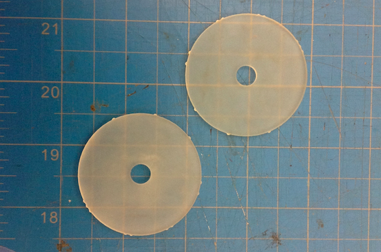
The rest of the design is basically that of the Hapkits, but modified. The Hapkits are taken apart down to only the acrylic, and then cut as shown by the red lines in the picture below. The top cut is to reduce the size and the one in the bottom so the wheels can fit. Once these cuts are made the Hapkit can be reassembled (minus the paddle, as is evident), and the braille wheel can be fit on the drive wheel.

The base is a 13x28 cm plate of acrylic laser cut to be slightly larger than the bases of the two hapkits together. It has a 5x8 cm hole in the middle where the wheels protrude. The Hapkits are positioned on this base facing each other with the wheels almost touching each other and their curved surfaces appear through the hole. Once they are secured in this position, the base is turned upside down and supported by the box.
Software Design
The basic algorithm for our Software Design followed this timeline: (1) assign next character, (2) get current position, (3) figure out which direction to turn to get to the next position the most efficiently, (4) execute the duty cycle while the position was still incorrect,
(1) Firstly, because we set up two cylinders, we figured out that there are 8 possible combinations for the alphabet, and we assigned each combination a number from 1 to 8:
1. 0 bumps
2. 1 top bump
3. 2 top bumps
4. all 3 bump
5. 1 middle bump
6. 2 bottom bumps
7. 1 bottom bump
8. 1 top + 1 bottom bump

We then set up an array for the alphabet (a is ‘21', b is ‘31', etc.), and for each combination, we calibrated the motor's position so that it would know where to go for each letter.
(2) There are two lines in our code which actually get the left and right motors' positions: " lastRawPosR = GetSensor(RIGHT); lastRawPosL = GetSensor(LEFT);" and " int rawPosR = GetSensor(RIGHT); //current raw position from MR sensor int rawPosL = GetSensor(LEFT);". The function "GetSensor" retrieved the current position information from the left and right motors by using "return analogRead(sensorPosPinL);". Of course, we needed to set up the sensors and the correct pins for data input and output, like sensorPosPinL and R. Since we hooked up the program to the left arduino board, we needed to connect the right arduino to the left one to get the right motor's sensor readings and communicate its due positions.
(3) We set up a function "MotorGoTo" which told the left and right motors where to go, and how to get there. We set up a distance variable, which we used to tell the motor to move clockwise or counter-clockwise. If the distance was smaller than maxEncoder (which was defined as half of a cycle), then the motor moved in that direction, but if the distance was greater than maxEncoder, then the motor would move in the opposite direction.
(4) We made the duty cycle of the motor a function of distance—the further it was, the faster it moved to its due position. However, we set it to not slow until it reached its new position.
There are some extra features in this code which helped us calibrate and fix some bugs such as learn mode, triggered by "=" and the flip option, where if the cylinders have flipped due to bugs in keeping track of flips for every 180 degrees, it would be easily fixable (use the ‘1' key to flip the left motor and the ‘2' key to flip the right motor).
Functionality
The device is intended to be used as a tool to learn braille. The adjacent wheels display the alphabet letter by letter. The user can slide his finger from left to right to feel the letter. Once they are ready they can tap the FSR on the side of the box to get the following letter. Since the braille is in accordance with the standards for braille embossed on paper it is a great way to become familiar with the size and position of the dots in your finger to then be able to move on to paper. The device is also implemented such that if the user pushes the wheels out of alignment, the wheels return to the proper position.
We could have improved our device by creating a File input function that would have translated virtual text files into our braille display. Ideally, to make a true haptic device, we would have liked to have another device that could sense and essentially "read" a braille sign, give the feedback to our haptic display device, which would in turn translate the information into the different letters of the braille alphabet.
At the Open House, we received many enthusiastic comments, as well as questions about how we went about to make our project. The most interesting reaction was by far how each user learned how to use the device: press here? Lift now? Feel it this way? Etc. At the Open House, we received many enthusiastic comments as well as questions about how we went about to make our project. The most interesting reaction was by far how each user learned how to use the device: press here? Lift now? Feel it this way? Etc.
Acknowledgments
Special thanks to Will Tucker and Dan Somen, TA's at Room 36, for their with the CAD file for the wheels. And a shout out to Mariel Lanas for helping us rethink our designs!
Files
Code and CAD drawings should be linked here. You should be able to upload these using the Attach command. If you aren't willing to share these data on a public site, please discuss with Allison. Also, in this section include a link to a file with a list of major components and their approximate costs.
- CAD files for the wheels. Attach:braillewheel.zip
- Arduino File. Attach:HapkitBraille3.ino.zip
References
http://www.brailleauthority.org/sizespacingofbraille/sizespacingofbraille.pdf
http://arduino.cc/en/Reference/HomePage