Ryan Zoe

The Final Product
Phlebotomist Training Tool
Project team members: Zoe Goldblum and Ryan Frankel
Have you ever had your blood drawn? Were you scared of the phlebotomist making a mistake? The Phlebotomist Training Tool aims to teach phlebotomists how to draw blood correctly, and in particular, how to not double-puncture a vein. Haptic engineering has already made an enormous impact on the medical world through devices like robotic arms. In our project, we aimed to expand this impact by taking medicine back to the basics: training. We aimed to create a virtual environment that mimicked the feeling of puncturing the skin and vein, so that phlebotomists-in-training can learn from their mistakes without making them on actual people.

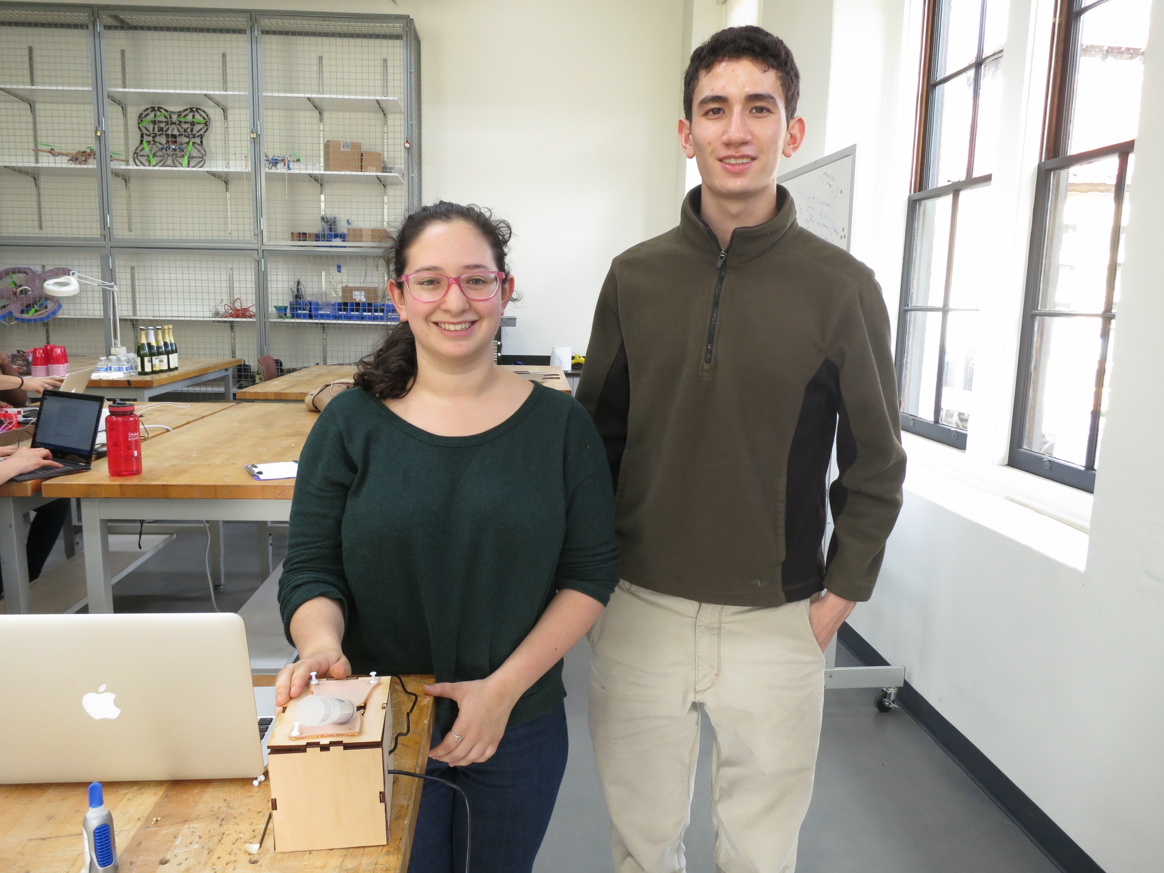
Us with our Training Tool!
On this page... (hide)
Introduction
While haptics has many applications, some of its most significant contributions have been in the medical field. There have been many endeavors to use haptics to improve the quality of medical care. Since the scope of our class is limited, we wanted to create a simple project that could benefit the world of medicine. While many haptic devices take what a medical doctor already knows and applies it, using technology like teleoperation, we wanted to create the opportunity for hands-on learning. Thus, we decided we wanted our user to learn how to draw blood by interacting with a basic haptic virtual environment. He or she could then apply those skills in the medical field. Therefore, our project is a one-degree of freedom device that relies on a virtual environment modeled off of human tissue and veins.
Background
There has been plenty of research into engineering applications to phlebotomy, or even just to needle insertion. We even heard on the day of our presentations about a new robot, the Veebot, which uses infrared technology to draw blood. Much of the research being done on needle insertion is done in the CHARM Lab here at Stanford, so we were very lucky to have Allison as a resource. We based our virtual environment off of previous haptic research in force feedback and needle insertion, which is linked in our resources. We based much of our design off of the Hapkit, and the Hapkit Hardware, since we were essentially creating a very small Hapkit with a capstan drive. Lastly, we based the capstan drive off of the design from the Haptic paddles, which was the old version of the Hapkit.
Design
Hardware

Internal Hardware
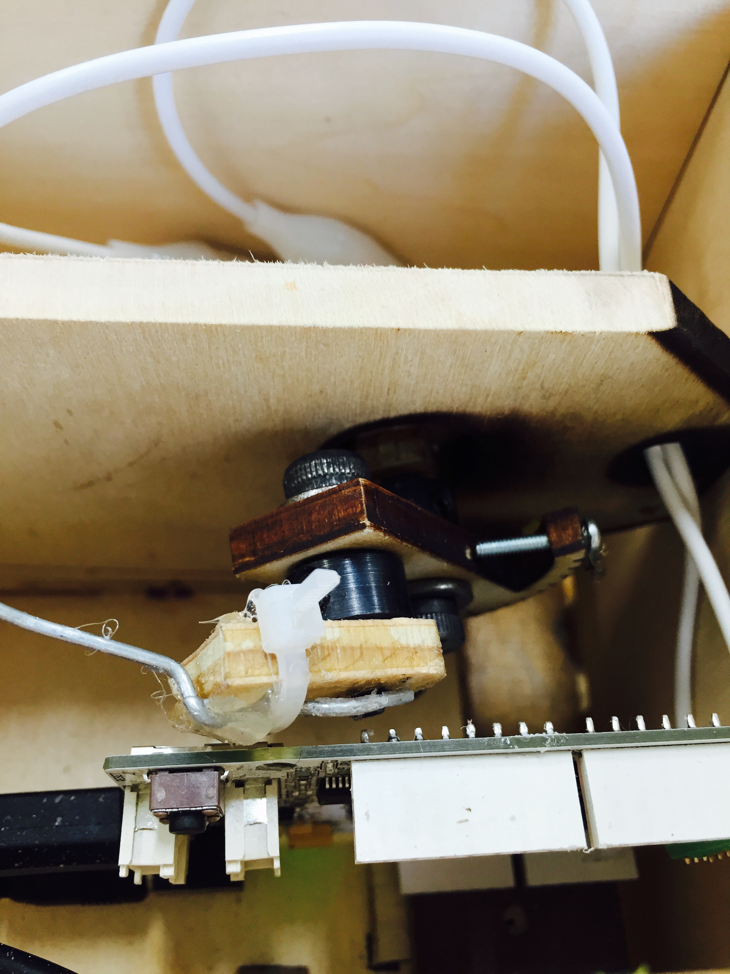
For our device, we needed to ensure that there was a small enough range of motion to make the device accurate. Thus, we took the design of the pulley from our Hapkits and essentially shrunk it down and mounted it on a stable surface. We also used the same motor shaft and MR sensors to generate force and track position of the pulley. In order to make sure the motor didn't slip, we installed a capstan drive on the small pulley. The capstan was created by attaching a flexible wire from the CHARM lab to the small pulley on one side with a screw, and pulling it as tight as possible while wrapping it around the motor shaft, and then screwing the wire to the other side of the pulley. As in the Hapkit, we used a Mabuchi 12-V motor and our custom Hapkit boards. All other small pieces were obtained either from the CHARM Lab or from the PRL. To contain the device, we created a wooden box whose pieces fit together like a puzzle around the internal hardware. We drilled several holes into the box so that our USB cable and our power supply for the motor could be connected.
The pulley and the box were created in Solidworks. We found the Basic Basswood Box files from the PRL website (linked below) particularly useful, as we were able to alter the dimensions to fit our device. Our small pulley was created from scratch, as was the structure titled "BigPulleyFinal(2)" which ended up being the surface upon which our small pulley was mounted. We laser cut our pieces from basswood that was a bit thicker than 1/4". We used basswood because we wanted the piece to be as light as possible while also offering the necessary sturdiness. While most of our parts were ideal, we did use hot glue on the box, as the pieces did not fit together perfectly.
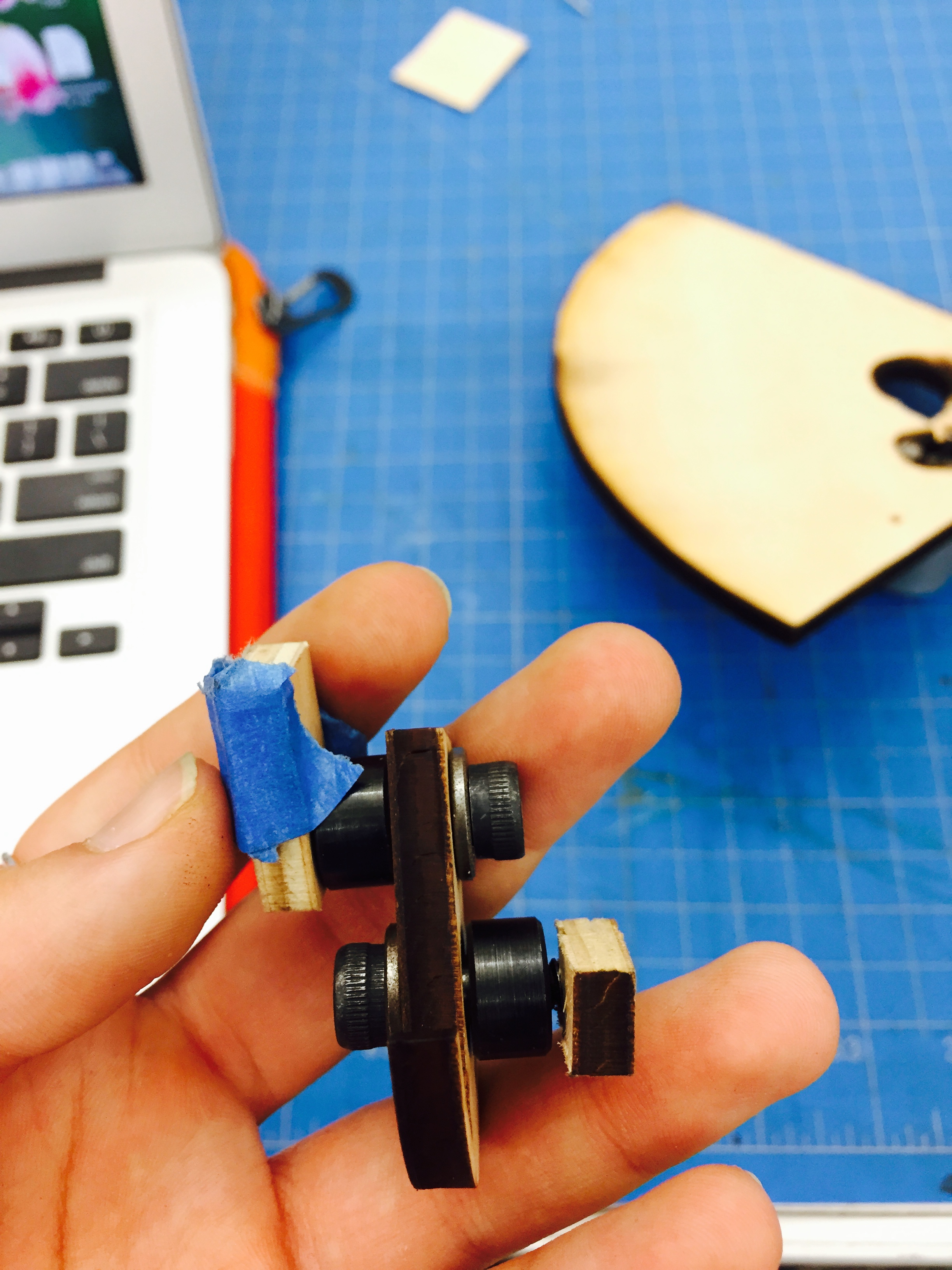
We also used a syringe with an inserted rod as our fake needle. The needle was attached to a scrap piece of wood that was mounted on the small pulley in a way so that it could rotate about the pulley (pictured below). The needle was attached using a zip-tie and copious amounts of hot glue. We used the same shoulder screw, bearing, and shaft collar as the ones used in the Hapkit to mount the wood to the small pulley. Lastly, we used a piece of fake skin on the top of the box for visual effect.

The Small Pulley in Detail
Software Design
We set up our Arduino board identically to the hapkit. We connected the M1 and M2 inputs on the Arduino board to the motor leads using alligator clips. A magnetoresistive sensor attached to the Arduino board picked up changes in the magnetic field of the magnet attached to the motor. The MR sensor generated an analog voltage between 0 and 5 V on a pin. The A/D converter read this voltage and converted it to a decimal number between 0 and 1023 to act as the raw position input for the code. The Arduino board communicated with the computer via a micro-USB. The serial communication rate was set at 19200 baud.
Our code consisted of generating various virtual environments as the needle moved through different simulated tissues in the arm.
We calculated the position of the needle relative to the starting point using polar conversions from the angle of the sector handle from the starting point into x,y coordinates. Our position was a function "a" that mapped the position on a secant line within the radius of the circle.
  double y = rh*sin(ts+ (pi/2));
  double x = rh*cos(ts+ (pi/2));
  float a = sqrt((x*x)-((y-rh)*(y-rh)))
Some forces also incorporated velocity tracking. Velocity tracking was based on the current "a" value, last "a" value, and the "a" value before the last "a" value. Velocity, denoted as "va" was computed according to the following algorithm:
  va = -(.95*.95)*lastLastVa + 2*.95*lastVa + (1-.95)*(1-.95)*(a-lasta)/.0001;
  lasta = a;
  lastLastVa = lastVa;
  lastVa = va;
To better reflect the real sensations of phlebotomy, we only wanted the user to experience forces if the needle was moving into the virtual arm, not while the needle was stopped or pulling out of the virtual arm. To do this, we created an "if statement" that made it so that if velocity were positive, the user would experience forces, but only a minimal force otherwise.
if (va>0) {
   …
   …
   …
} else {
force = 0;
}
Forces were generated at specific ranges of "a" values that correlated with the actual depths of the skin, skin tissue, and veins in a human arms. The difference in the types of forces were meant to model the differing sensations of these tissues. In our code, we used a series of "else-if statements" to tell the motor at what "a" position it should output forces and what kind of force it should output at those positions.
We rendered the surface of the skin and both vein walls as virtual springs that increased in force as the needle moved past the "a" value of the starting position of each environment. We decided that a simple spring based on the formula F=-kx was the best choice. The skin and vein walls were assigned distinct k values so that the user could feel a slight pop upon puncture of the vein walls. We rendered skin tissue as a continuation of the spring at the skin surface with an added virtual damper that increases resistance with increased velocity. In real blood withdrawal, resistance to the needle increases based on speed and depth in the skin tissue until the vein is reached. After the second virtual vein wall is punctured, we also rendered a virtual damper, but without an added spring force. Our dampers were based on the simple damping formula F=-bv. Finally, the inside of the vein was rendered as a very minimal force to reflect the lack of resistance phlebotomists feel inside the vein.
 //Declare tissue variables
  double k_skin = 150;
  double b_skin = .75;
  double k_vein = 125;
  double k_vein2 = 225;
  double b_withdrawal = .1;

 if (va>0) {
   if (a<.0009) {
      force = 0;
    }
      else if (.0009<a && a<.0012 ) { //surface of skin
      force = -k_skin*(a-.0009); //force of skin puncture
    }
      else if (.0012<a && a<.003) { //skin tissue
      force = -k_skin*(a-.0009) + -b_skin*va //force moving through skin tissue
    }
      else if (.003<a && a<.0045) { //vein wall
      force = -k_vein*(a-.003); //force of vein wall puncture
    }
      else if (.0045<a && a<.009) { //inside of vein
      force = .01; //force moving through inside of vein
    }
      else if (.009<a && a<.0105) { //second vein wall
      force = -k_vein2*(a-.009); //force of second vein wall puncture
    }
      else if (.0105<a) { //beyond vein
      force = -b_skin*va; //force moving beyond vein
    }
 } else {
   force = 0;
 }
Functionality
To use the Phlebotomist Training Tool, the user must start from the position "a" = 0 on the serial monitor. This ensures that the needle is fully retracted and at an ideal angle to "penetrate" the skin. The user can then push the needle into the virtual arm. In doing so, the user should feel initial resistance when puncturing the skin, a slight pop upon puncturing the first vein wall, no resistance inside the vein, a smaller pop upon puncturing the second wall, and resistance afterwards. After becoming acquainted with the tool, the user can experiment by moving the needle faster or slower, or avoiding double puncture or intentionally causing double puncture. With each use, the user should move the needle back to "a" = 0 on the serial monitor.
During the open house, the device functioned mostly as planned and guests were able to feel a distinct virtual environment of the arm and vein. They found it challenging to avoid double-puncturing the vein, which proves the usefulness of training in a virtual environment rather than on a live subject. Guests' most common questions were "How did you decide what kinds of dimensions forces were appropriate to model phlebotomy since you don't have medical experience?" and "What types of force equations did you use for each given position?"
The biggest problem we encountered with the device was that the needle would be moved to a position before the "a" = 0 starting point and experience all the forces in reverse. Most of the time, this had few consequences beyond confusion on the part of the user. We could have avoided this by putting up a physical barrier to prevent rotation to that side. Another problem we experienced was that the motor would become uncalibrated with the Arduino board, either due to mechanical slipping or slow communication between the magnet and sensor. This could have been resolved with either a better capstan drive or a better MR sensor depending on the source of the problem.
We could have improved our device by incorporating some visual feedback. Phlebotomists tell they've punctured the vein not only by a slight pop, but also a red flash inside the collection tube. In our code, we could have rendered a graphic displaying the positions of the needle tip, skin surface, and vein walls that would turn red upon vein puncture. We also could have had some visual indication of double-puncture. In the future, we might also add a second degree of freedom so that the user can experiment with the angle of puncture instead of just depth.
How it's used:
Acknowledgments
We would like to thank Allison and all the members of the CHARM lab who took their time to help us. We would also like to thank Jordan for his help with Solidworks and Dr. Edward Frankel for providing the necessary medical information. Additionally, special thanks to Will, Macey, Lea, Jade, and all the other PRL TAs who helped make this project a success.
Files
Code
Attached are the zip files with our final arduino code for the training tool.
Hardware
Attached are the Solidworks Files for the small pulley and the box, along with the original version of the large pulley on which the small pulley is mounted.
Major Components
Attached is the list of major components and their costs for our device.
References
- https://productrealization.stanford.edu/resources/processes/laser-cutting
- Oleg Gerovich, Panadda Marayong, and Allison M. Okamura. "The Effect of Visual and Haptic Feedback on Computer-assisted Needle Insertion*." Computer Aided Surgery 9.6 (2004): 243-49. Taylor & Francis. Web.
- Dr. Edward Frankel, M.D., interview on anatomical structure and sensations of blood withdrawal

