

Megumi Alema Kira

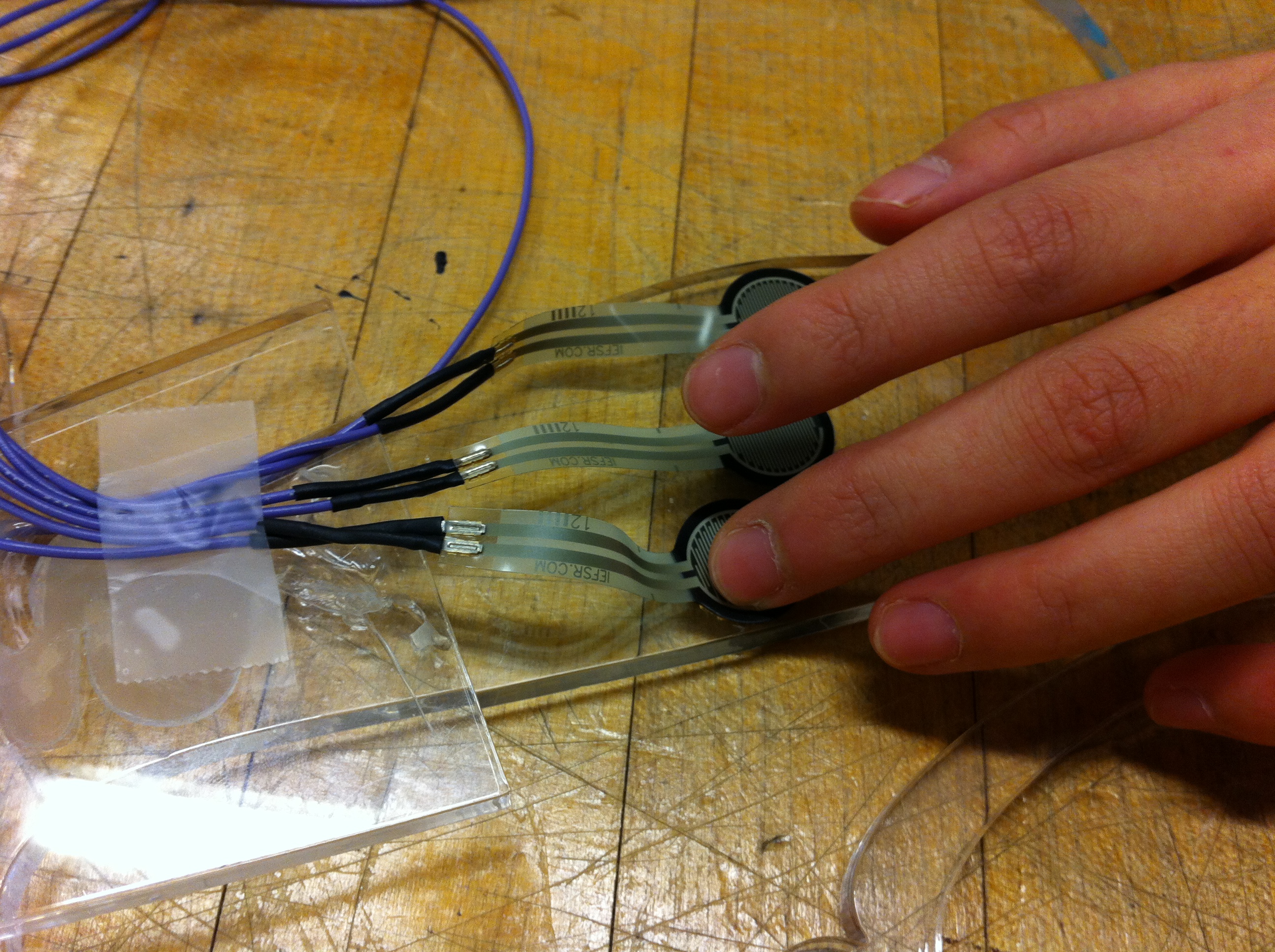
Caption:
Depth-sensing glove on demonstration day.
Depth Perception For the Blind
Project team member(s): Megumi Sano, Alema Fitisemanu, and Kira Jan
For our final project, we created a glove that detects objects in the direction that the palm is facing and vibrates with varying intensity depending on the distance to the object. The motivation behind the project was a desire to transfer visual information into haptic feedback. The final product successfully provided vibration feedback in four levels of intensity for four different distances from obstacles.
Introduction
As we learned about engineering haptics throughout this course, we were fascinated with how much information an individual can acquire from simple haptic feedback, as well as how easily we can program such feedback with the use of simple calculus and geometry. To maximize the outcome of what we learned in class, we wanted to create a device that helps individuals who share a perceptual reality different from typically developing peers and improves their quality of life.
Traditionally, many systems that assist visually impaired people have used auditory cues to inform them about visual information that they lack. One such system is the screen reader, which transmits text displayed on the computer screen into auditory information, sound produced by a synthetic voice. However, many users complained that it is difficult to process auditory signals, which led to the increased use of devices such as refreshable braille displays, which involves translation of visual information into tactile information. Similarly, we decided to translate visual information into haptic feedback so that blind users can sense obstacles in front of them through their sense of touch. Additionally, we were all interested in building a multimodal system (a system that integrates different sensory systems), which had not been covered in the class.
Background
Similar Projects:
There were two projects that we saw that were very similar to our depth-sensing glove:
HandSight (a glove-mounted device): https://www.theengineer.co.uk/issues/february-2015-online/vibrating-glove-uses-ultrasonic-echolocation-to-help-the-blind/
Head-mounted device: http://grathio.com/2011/08/meet-the-tacit-project-its-sonar-for-the-blind/
Although it is important to be able to sense head-level objects, we wanted the user to be able to sense objects anywhere around them in a certain range of distance. Therefore, we decided to use a wearable device in the form of a glove that makes use of the free movement of the arm. With the range of movement of arm, the user is able to investigate specific areas of interest, as well broader areas, in greater depth. Regarding our code, the code was based on the original Haplink code. Additionally, Haplink Designer Melisa Martinez created the code for the ultrasonic sensor as well as the vibration motor. Her code allowed us to receive proper input from the ultrasonic sensor, and give proper output to the vibration motor. She also helped us in making proper electrical connections,and understanding our circuit boards and their voltage needs. Melisa Martinez was an integral part to the success of our project.
Design

Caption:
Depth-sensing glove on demonstration day.
Hardware design
Our primary concern with the glove itself was finding a glove which would fit a variety of hand sizes. For that reason, we chose to use a store-bought knit glove made out of polyester, nylon, and spandex. In choosing the glove, we considered its stretch and the thickness of a material; we wanted to ensure that the vibration could be felt through the glove. In order to ensure a better fit for larger hands, we cut off the fingers from the glove. We later used the material from one finger to house the vibration motor in its plastic tube (taken from a pen). Then, we used another cut finger from the glove to hold the first of the wires from the vibration motor to ensure they would not be ripped out. Due to the difficulty of machine-stitching the stretchy material, we used fabric adhesive to secure the vibration motor pouch to the glove. We designed the glove for right-handed people, assuming most users would be right-handed.
To house the vibration motor, we found a plastic tube from a pen and cut it down to size. The vibration motor fit snugly within the housing, and we did not need to use any adhesive. We secured the ultrasonic sensor to the palm of the glove with velcro so that it could be easily removed in case of damage or to better clean the glove. In cutting the wires for the ultrasonic sensor and vibration motor, we made sure to leave several feet in order to allow for maximum movement of the user's hand and arm. We used heat-shrink tubing around the wire connections to the motor. Once we had all the wires, we also used heat-shrink tubing to bundle the wires together to avoid damage from tangling or pulling. We placed heat-shrink tubes of approximately 2.5 cm in length spaced about 18 cm along the bundled wires.
Materials
- 1 glove
- 1 ultrasonic sensor (HC-SR05 4.5-5.5V DC 10-40mA)
- 1 vibrating motor (1.3V DC 80mA)
- 1 Electronics board
- 1 Microcontroller board (NUCLEO-F446ZE)
- 1 5V power supply
- 2 USB cables
- 1 strip of Velcro
- Plastic tube for vibration motor housing
- Heat-shrink tube (minimum 1 for securing the wires at the base of the vibration motor, recommended at least 3 full tubes for securing all the wires together at the end)

Caption:
The original design with the vibration motor on the back and ultrasonic sensor on the front. Sketch by Alema Fitisemanu

Caption:
The almost-completed glove before the securing of wires with both the motor (enclosed in a pocket) and sensor (exposed) on the front.

Caption:
The actual product with both the motor (fully enclosed in a pocket) and sensor (exposed) on the front.
Software design
The software component of our project was developed using Arduino. We wanted to convert information (distance from the sensor to the object) detected by the ultrasonic sensor into force feedback through the vibrating motor. We decided to change the voltage of the motor depending on the distance. The shorter the distance, the higher the intensity of the vibration will be. In order to do this, we changed the duty cycle of the motor. The duty cycle represents the ratio of "on pulse" compared to one period cycle, expressed as a percentage. If the original voltage is 5V, we can use a duty cycle of 0.25 to make the resulting voltage 1.25V.

In the above diagram, the glove is positioned at approximately 22.0 cm, which is in the range of 20.0 to 30.0 cm. This means the motor will vibrate at a duty cycle of 0.14, which gives a voltage of 0.70 V.
Functionality
The user wears the device on their right hand so that the ultrasonic sensor and the vibrating motor are on the palm. As the distance between the ultrasonic sensor and an object decrease, the user should experience vibration which increases in intensity every 10 cm, with the highest intensity felt between 0 to 10 cm from the object.
Interesting comments:
At the demo, some of the users who experienced this device commented that they were surprised by how much they could learn by receiving haptic feedback. One user expressed excitement learning that she could tell how many objects were in front of her, as well as differentiate which of the objects were farthest away. Many users enjoyed the different levels of vibration intensity and how clearly those levels described their physical environment. Although the glove was much a prototype, the users loved it's functionality as another way to experience their surroundings. We had users not only using the depth-sensing glove on our demo, but on their friends, nearby tables, and other surrounding objects. It was a great experience to see people get excited about our project and its capabilities. Additionally, we had former ME20N students compliment us on how nicely assembled our project was. Talking with them, we learned about their experiences in the class years before. Regarding our demo, they enjoyed how our device was wearable, and how the clear levels of haptic vibration helped them to map out objects. It was a fun time conversing with them, and hearing their stories reminiscing over their past ME20N adventure. We got to learn so much from these past students and other users.
Functionality:
The device functionality was not fully as planned. The range of the ultrasonic sensor decreased from 45 cm to 30 cm over the course of the hour-long demo. However, despite the ultrasonic sensor not working as planned, the vibration feedback worked well. Users reported that they clearly felt the varying intensities of vibration as the proximity of their hands increased. The vibrations were also consistent and smooth. We had one user comment that "the vibration feels calming and soothing to her hand."
Improvements:
An improvement to the device would be to increase range of the ultrasonic sensor. As one user suggested, we could create different types of vibration pulses to detect different types of surfaces. Different vibration feedback could also be produced for more qualities of obstacles with added sensors (e.g. texture, color, temperature). Furthermore, a large improvement that could be made would be to make the device wireless with a battery pack and bluetooth operation. In that way, users would not have to remain so close to the computer and limited in movement by the wires.
For the hardware, creating a more durable glove with stronger attachments and fully covered (if not wireless) wires would aid in the time it takes to put on and take off the glove without damaging equipment. A slightly stiffer glove would be help with stability of the sensor and vibration motor on the mount. If we could remake the glove, we would place the ultrasonic sensor higher up on the palm because we found that the natural angle of people's hands tended to point the sensor downward so that the sensor would pick up the table. Moving the sensor up by 2-3 centimeters would help eliminate this problem.
Acknowledgments
We would like to thank Dr. Allison Okamura for being a wonderful teacher and giving us expert advice throughout the project.We are also grateful to Melisa Martinez, Kaitlyn Gee, and Tyler Cloyd for helping us with everything from getting the Hapkits/Haplinks to work, to translating our ideas into our final product. We would also like to thank the TAs of Room 36 in the PRL for being very patient and helpful with our questions.
Files
- Depth-Sensing Glove Code (main.cpp file only): Attach:GloveCode.pdf
- Component List with Pricing: Attach:ComponentList.pdf
References
Baldwin et al. (2017). "The Tangible Desktop: A Multimodal Approach to Nonvisual Computing." ACM Transactions on Accessible Computing. 10(3). https://dl.acm.org/citation.cfm?id=3132048.3075222
Wiki examples
Here is how to link a youtube video:
Here is how to link to a file (note that you will need to compress/zip your code and CAD files into zip files so that that wiki will let you upload them): Attach:HapkitTest.ino.zip
Here is how to add an image: 
Here is how to attach an image with the height adjusted (to 100 pixels)
Here is how to attach an image with the width adjusted (to 200 pixels)