

Sarah Bryce Elina

Sarah wearing the headband at
at the Haptics Open House.
Haptic Headbandtest
Project Team Members: Elina Thadhani, Sarah Pinto, and Bryce Huerta
Our goal for this project was to build a wearable haptic feedback device that allows visually impaired people to obtain information in real time about their surroundings. Ultrasonic sensors paired with vibration motors relay information about objects in the surroundings of the user. The measured distance of the object (from three distinct ultrasonic sensors) relates to the vibration of corresponding vibrational motors. A headband was used to mount our hardware and provide haptic feedback directly to a person's forehead.
Introduction
From the start, we knew we wanted to build a device that could help people suffering from a physical disability. Haptic engineering has been used before many times to help assist people with varying disabilities, so we wanted to explore this section of the field. We had relatively limited familiarity with the electronics and programming necessary to build a highly complex system; we wanted to choose a project that was simple but useful for a certain population. With our device we strove to give feedback to individuals in a way that is not dependent on them being able to see or understand their surroundings directly. Thus, we created this haptic device that allows the user to determine his or her basic surroundings and navigate a room based purely on force feedback.
Background
Though we came up with the idea for the project completely on our own, our group was by no means the first group to have constructed a haptic device focused on the visually impaired. In 2010, Steve Struebing created a device called the "Haptic Assisted Locating of Obstacles," or H.A.L.O. The machine that Struebing created is remarkably similar to our own, as it utilizes multiple ultrasonic sensors and vibration motors attached to a headband. While more complex, using five of both ultrasonic sensors and vibration motors, it accomplishes the same task as our model: providing haptic feedback for visually impaired people to navigate an environment. Struebing's device was also mobile, as a user could move around while carrying the electronics in a backpack. Similarly, we constructed a box to hold our electronics equipment. For further reference, Struebing's project is available here.
Design
Hardware design
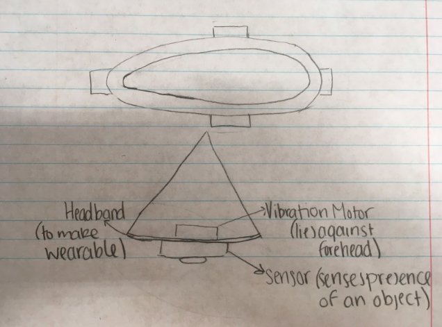
Initial concept for a headband based
haptic device.
Our hardware consisted of an elastic headband with three ultrasonic sensors and three vibration motors attached to it. The ultrasonic sensors were sewn onto the outside of the headband. The three vibration motors were glued inside three plastic motor caps (see Files) and sewn to the inside of the headband to allow the user to best feel the changes in pulse frequency. Each sensor was paired to a motor in one spot on the headband, to allow the user to best feel the changes in pulse frequency. Each sensor was paired with a motor, and each pairing was placed at a specific point on the headband. We extended the wires attaching the various sensors and motors to allow them to reach the boards located in the box affixed to the users back with a belt. The boards and circuitry were then connected to both the computer and 5V power source by extension cords as to allow the user a relatively free range of motion.
The hardware was designed for wearability and mobility. We chose to consolidate the wires into a box as opposed to extending them more to allow the user to put on and take off the device with relative ease. This design choice also allowed us to give the user a larger range of motion. The user was able to operate the device within a 3 meter radius of the computer. Ideally, the device would be completely portable and not restricted to a 3 meter radius from the power source.
Our hardware consisted of an elastic headband with three ultrasonic sensors and three vibration motors attached to it. The ultrasonic sensors were sewn onto the outside of the headband and the vibration motors were fastened on the inside to allow the user to best feel the changes in pulse frequency. We extended the wires attaching the various sensors and motors to allow them to reach the boards located in the box affixed to the users back with a belt. The boards and circuitry were then connected to both the computer and 5V power source by extension cords as to allow the user a relatively free range of motion.
The hardware was designed for wearability and mobility. We chose to consolidate the wires into a box as opposed to extending them more to allow the user to put on and take off the device with relative ease. This design choice also allowed us to give the user a larger range of motion. The user was able to operate the device within a 3-meter radius of the computer. Ideally, the device would be completely portable and not restricted to a 3-meter radius from the power source.
Software design
The software design incorporated some base elements of the original Haplink project. However, new files pertaining to the ultrasonic sensors were included, such as "haplink_ultrasonic.cpp" and "haplink_ultrasonic.h." Within "haplink_ultrasonic.cpp, "only the function "HaplinkHeadband2" was called to make the device function. The code for this function consisted of three sets of "if-else" statements pertaining to each combination of ultrasonic sensor and vibration motor. Each ultrasonic sensor returned a distance value (in centimeters) for object proximity, and these values were printed using "getHaplinkUltrasonicDistance()." Within each "if-else" statement (with one set corresponding to one individual ultrasonic sensor), we defined the distances at which a force should be outputted to the associated motor.
Though initially we had the force output by the corresponding motor vary as the distance of the object to the sensor decreased, we decided to have the motors pulse at different frequencies as the object became closer as the effect was more noticeable to the user. To have the motors pulse, we defined a static internal counter system with three separate counters (counter1, counter2, and counter3) with each one corresponding to a separate pulse. Thus, counter1 was the pulse value when an object was from 0-7.5cm away from the sensor, counter2 was the pulse value when an object was detected as 7.5-15cm from the sensor, and counter3 was the pulse value when the object was 15-30cm away from the sensor; otherwise, if the object was detected as 30-100cm away from the sensor, no force at all was output from the motor. Thus, we varied the pulse or frequency of force output for the motors, but maintained a constant force output for the vibrating motors when the distance of the object was under 30cm.
For each ultrasonic sensor, we used the corresponding "getHaplinkUltrasonicDistance()" for our progression of "if-else" statements. As mentioned above, for any given sensor, if the object of interest was between 100 cm and 30 cm, then no force would be called for. This was achieved by setting "updateDutyCycle(0.0)" so no force would be outputted to the corresponding motor. Likewise for under 30cm, we had a force output on the motors called "updateDutyCycle(0.2)" to output this constant force.
Functionality
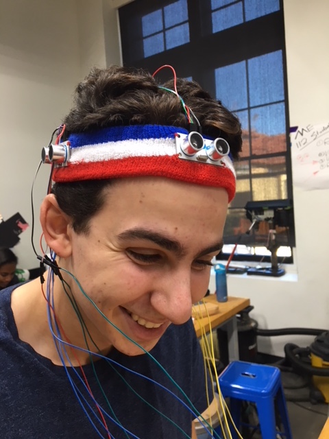
Close up of the headband
modeled by Bryce.
When the ultrasonic sensors register an interruption in the emitted wave, the code called for the vibration motors to turn on. The motors were set up in a way so that the user was able to distinctly feel which motors were turned on and which ones were not. This aspect allowed the user to now from which direction the obstacle was approaching as the motor behind the ultrasonic sensor sensing the obstacle would vibrate. The user could also gauge how far away the obstacle was as the pulse of the vibration of the motors increased as the sensors detected the obstacle moving closer.
At the Haptics Open House, someone asked us what would happen if the obstacle was approaching at 45-degree angle to the user. The way that the sensors are currently set up makes it so that both sensors register the obstacle. Ideally, we would have more sensors set up so that the user could locate exactly where the obstacle is approaching from. Problems arise when attempting to add more sensors because not only does the board not have the capacity to handle more sensors, but also the waves sent out by the sensors begin interacting with waves sent out by the other sensors. When more than one sensor is activated by a singular object, it creates confusion for the user about which direction the obstacle is approaching from.
In order to improve our device, we would need to add more sensors and increase the range of said sensors. Increasing the range would allow the device to be more practical in actually allowing visually impaired people to navigate spaces. In addition, we recognize that not all obstacles will be detected by sensors on the head, as obstacles in everyday life are not limited to obstacles at head-level heights. For this model to be used practically by a visually impaired individual, it would have to be paired with perhaps a smaller version at waist, and ankle level.
Although in an ideal world we would implement these changes, we recognized the limitations of our design in the beginning of the process and achieved the goals we initially set for ourselves.
Video from ME20N Open House. Haptic Headband functionality demonstrated by Sarah Pinto.
Acknowledgments
We would like to thank Professor Allison Okamura, Melisa Orta, Kaitlyn Gee, and Tyler Cloyd for all of their help with our projects. Melisa was especially helpful in assembling the boards and electronics, and we certainly could not have completed this project without her help.
Files
Mbed code used for Haplink Headband. This code features an updated Haplink library provided by Allison that has been designed for ultrasonic sensor use.
Specifications for our ultrasonic sensors, as well as price per unit.
Specifications for our vibrating motors, as well as price per unit.
SolidWorks file for motor caps. Three were used for this project.
References
http://www.instructables.com/id/Haptic-Feedback-device-for-the-Visually-Impaired/