

2023-Group 11
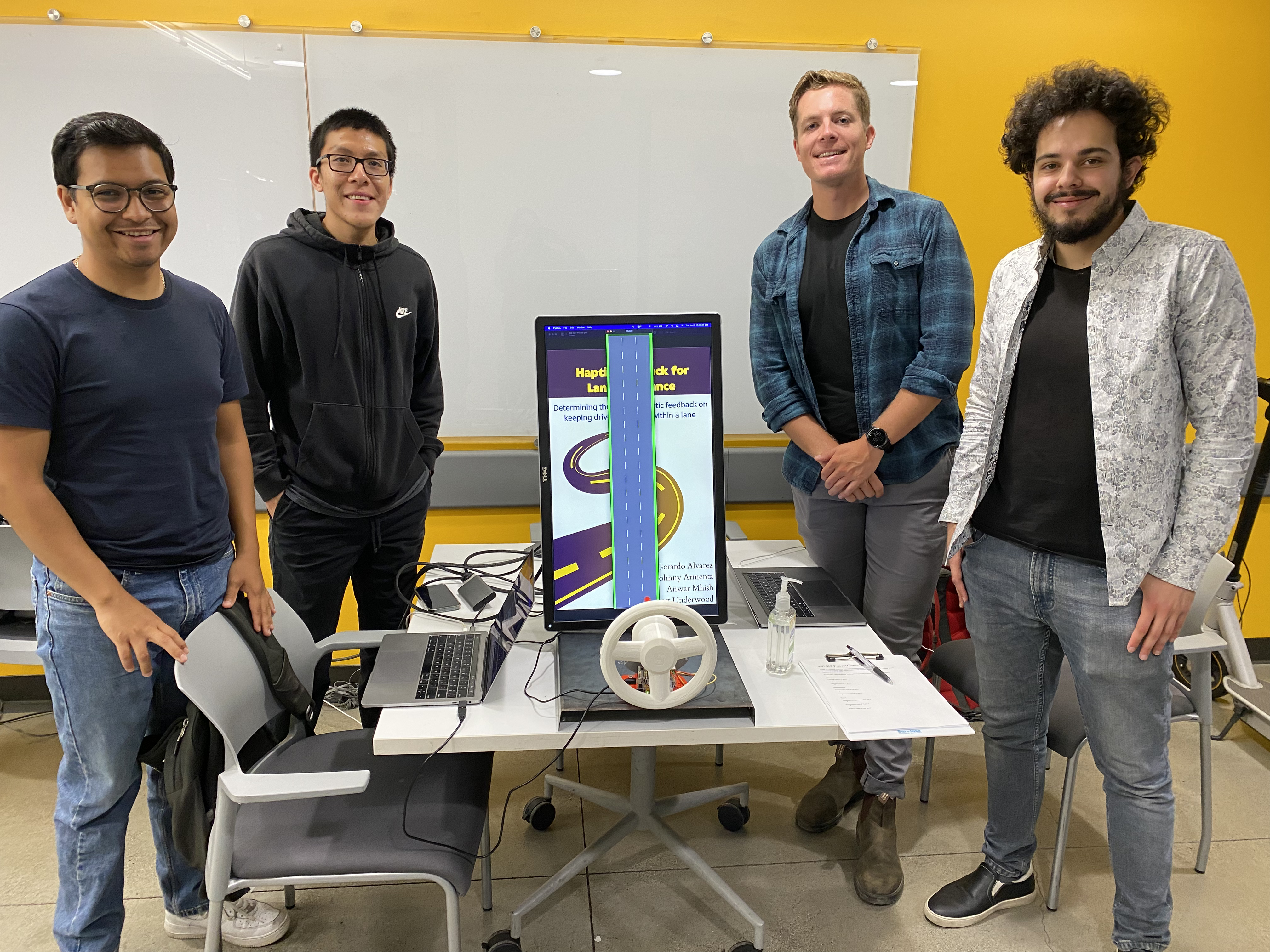
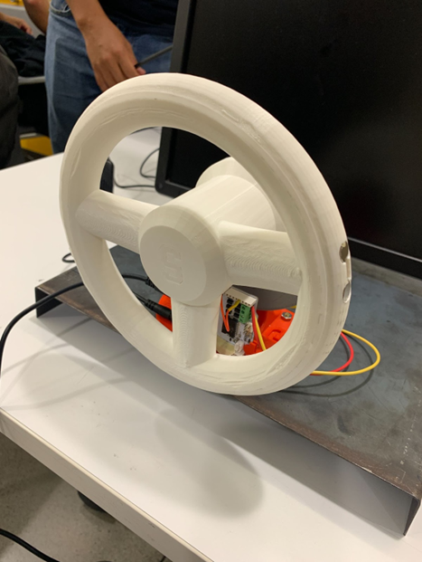
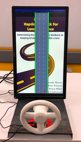
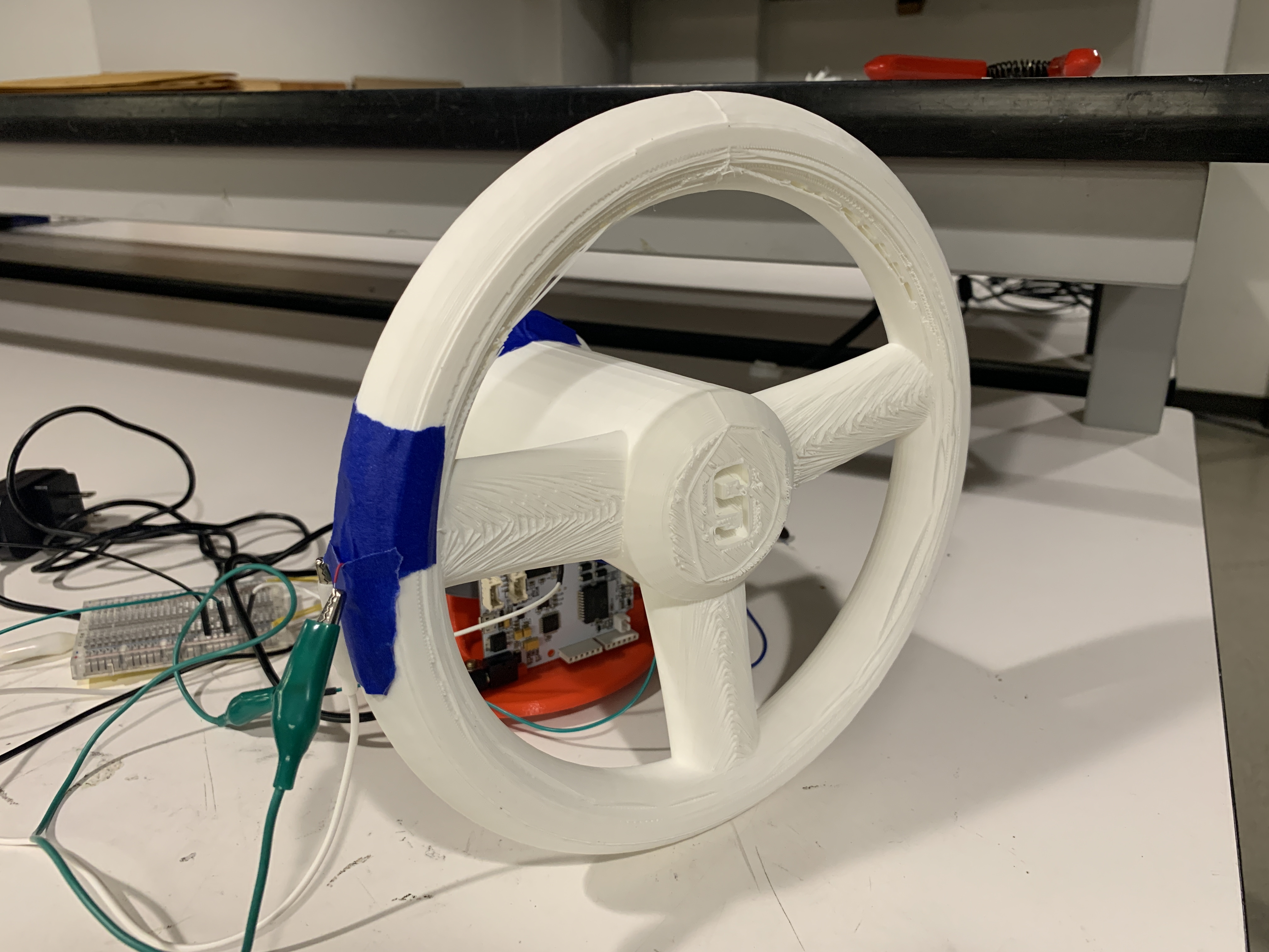
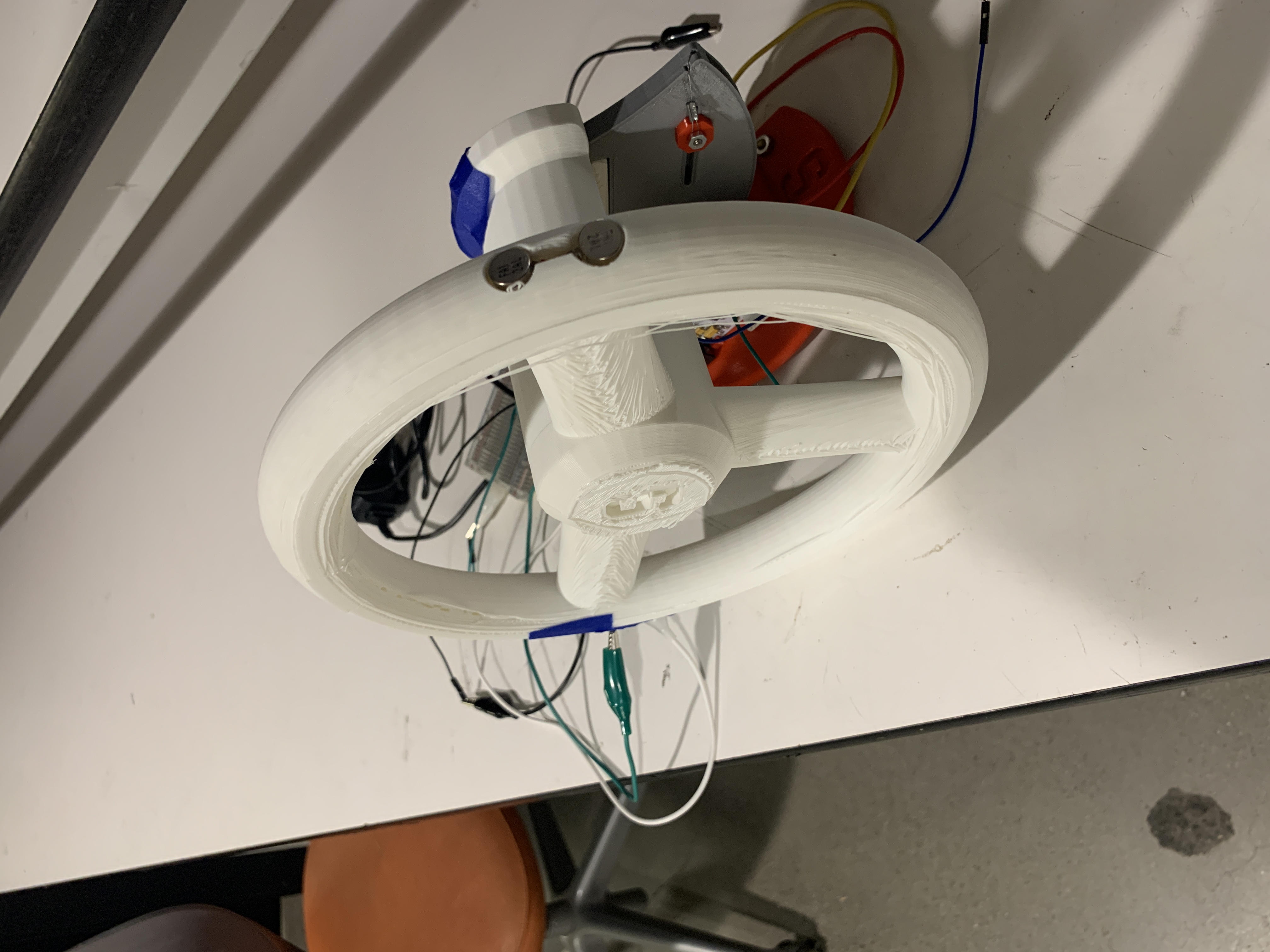
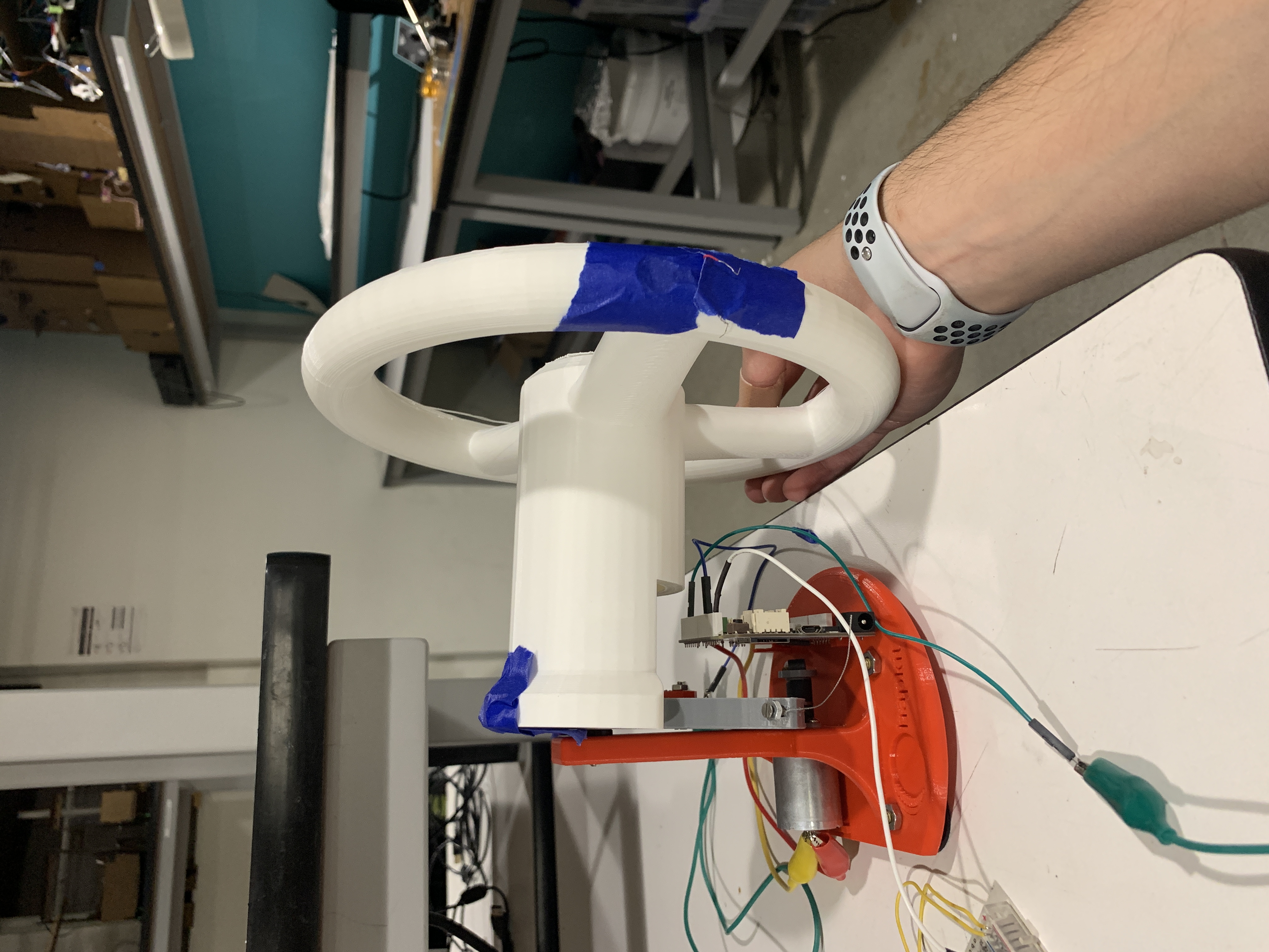
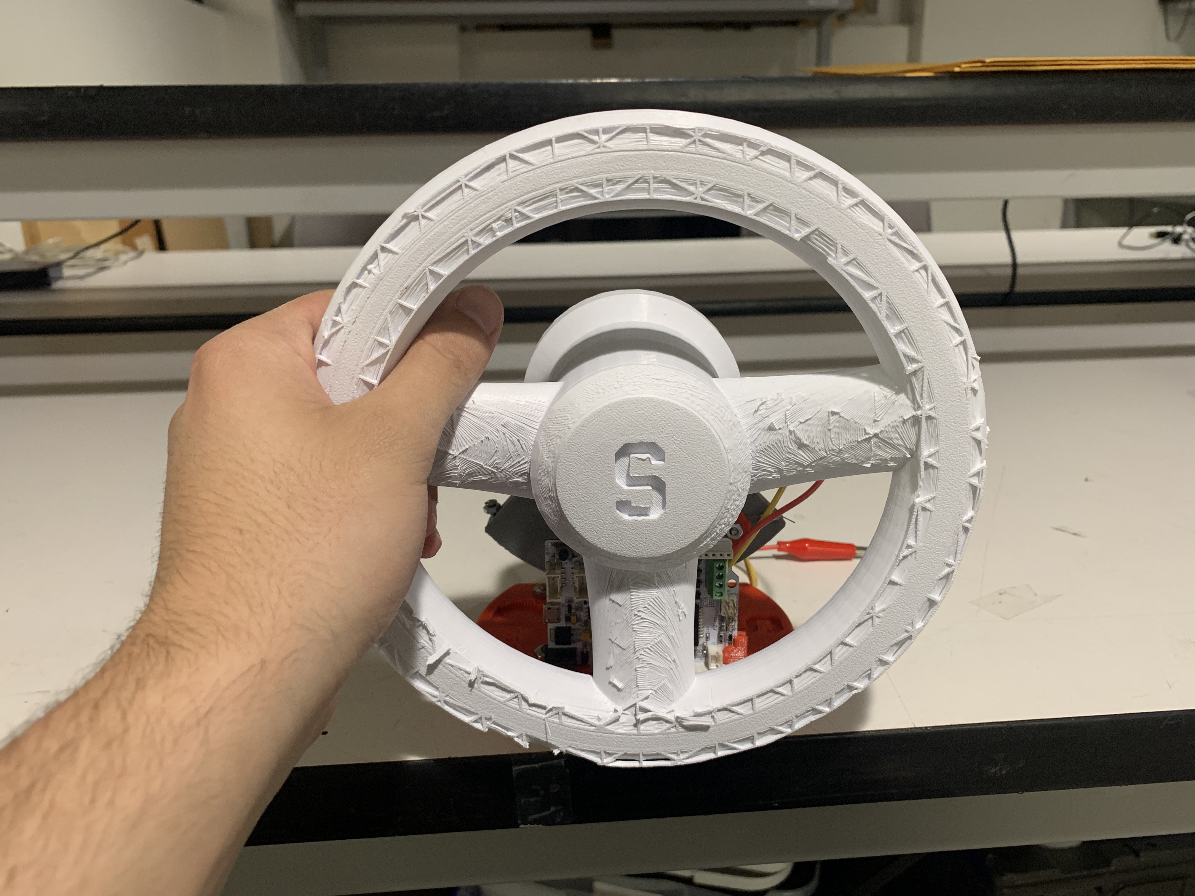
Caption: Team on demo day with haptic-assisted steering wheel setup.
Lane Departure Warning System Using Vibrotactile and Force Feedback
Project team members:
Gerardo Alvarez
Johnny Armenta
Anwar Mhish
Scott Underwood
Our project aims to assess the effectiveness of utilizing a haptic-assisted steering wheel to help drivers stay centered within their lane. We compare two different modes of haptic feedback on our steering wheel - vibration alone and vibration paired with force feedback - to the same steering wheel with haptics turned off. We gauge performance by quantitatively analyzing their performance using two metrics and collecting qualitative feedback from 20 different participants regarding their preferred haptic feedback mode. The metrics include the user’s average distance from the center of the lane and the vehicle’s average absolute orientation. The results of our study seem to suggest that while participants indicate they prefer either vibrational or vibrational and force feedback, the feedback has no significant impact on their driving performance in the scenario tested.
On this page... (hide)
Introduction
Our team sought out to study how haptic feedback can be used as a means to turn the traditional steering wheel into a more effective lane-assistive device. Many newer vehicles come equipped with systems that can provide various forms of feedback through the steering wheel. These include lane departure warning systems that provide visual, audible, and/or tactile warnings to alert the driver when the car approaches lane markings, lane keeping systems that provide steering support to prevent the vehicle from departing the lane, and lane centering systems that provide steering support to center the vehicle in its lane [1]. However, these systems can be overpowering, distracting, and ineffective. Our project serves as an exploration into a simple haptic-assisted steering wheel aimed at improving the driving experience from a safety and comfort perspective.
Background
Previous studies have looked at the use of haptic feedback technologies to enhance occupant safety in vehicles. Gaffery et al. found that the use of vibrotactile feedback in both steering wheels and pedals provide intuitive alerts to drivers, as the feedback mimics the bumps employed at the edges of lanes on some roads [2]. Beruscha et al. investigated the effectiveness of steering wheel torque feedback and vibrotactile feedback applied by eccentric mass motors in steering wheels, finding that torque feedback was often confused with natural torques occurring from tire interaction with the road, while vibrotactile feedback was recognized at a much higher rate [3]. Finally, Onimaru et al. found that vibrotactile feedback applied by loudspeakers broadcasting white noise improved steering accuracy on a course with multiple corners when compared to a no feedback scenario and a scenario with visual feedback in the form of symbols on a screen [4]. These studies suggested that providing the user with vibrotactile feedback enhanced their steering performance and ability to identify the edges of road or path lanes. As a result, our study will look at testing this type of feedback along with force feedback to determine which provides the best assistance to the user.
Methods
Mechanical Design
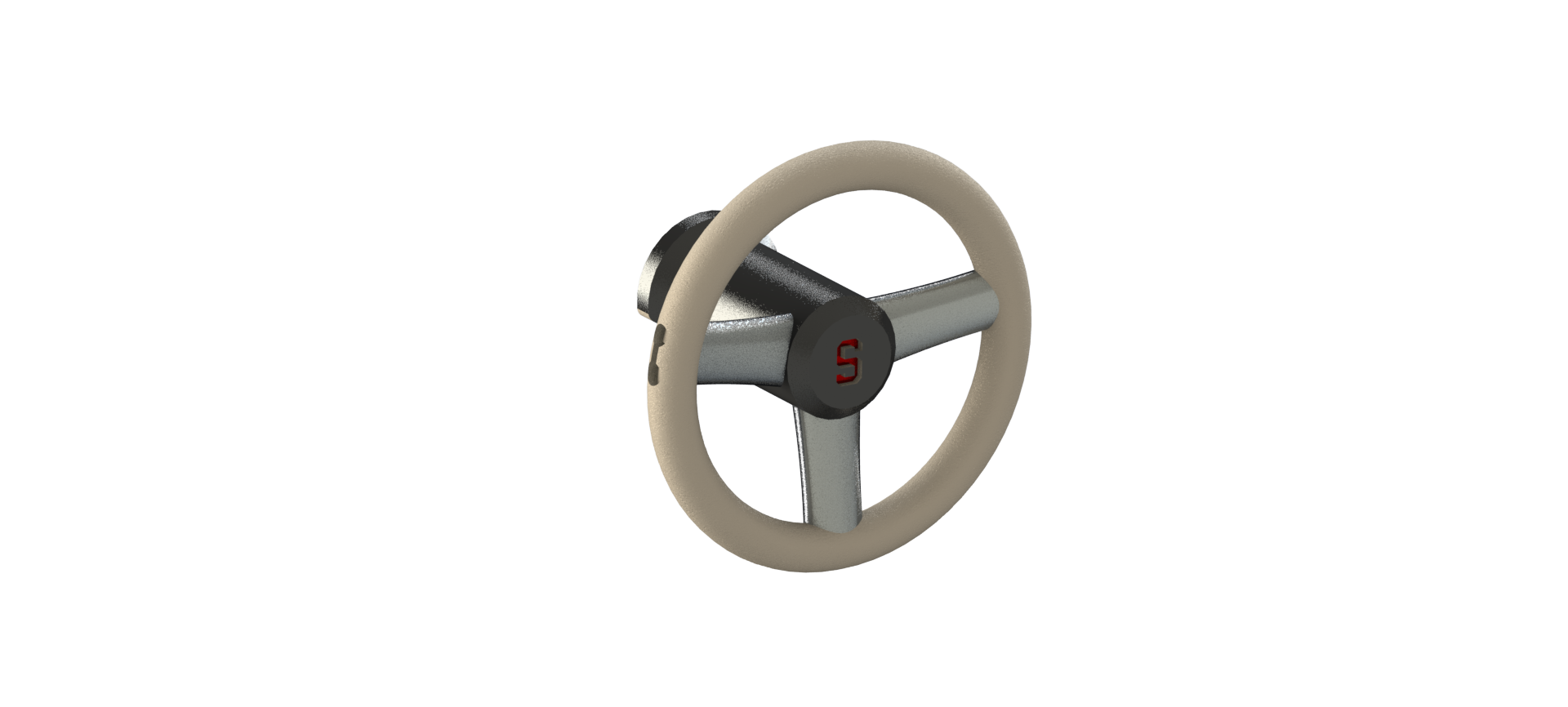
Our project was constructed using a 3D printed steering wheel made out of PLA, which was fabricated using a PRUSA FDM printer. The printing infill was chosen to be around 15% to ensure a good balance between strength and achieving a light weight.
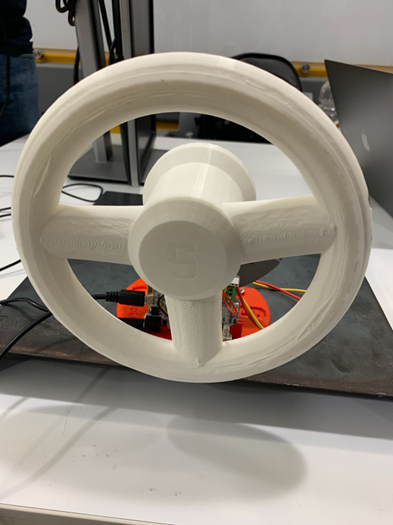
Final steering wheel:
During the prototyping stage, multiple designs were created and tested - a yoke steering wheel and circular steering wheels of different diameters. Within the steering wheel, recesses for vibration motors were created to hold two motors on each side of the wheel, and an inner channel was also created for routing the wires through the steering column to the arduino board. The steering wheel connects to the bottom sector of the Hapkit through the steering column. The vibration motors were placed on the lateral (outer left and right) sides of the steering wheel so they make good contact with the user's palms when placed in a natural position around the steering wheel.
The yoke steering wheel was initially created because we were unsure if the user would be able to differentiate between the left and right vibration motors on the circular steering wheel. However, after testing we confirmed that this was not an issue with the circular steering wheel, and we chose the circular steering wheel because it felt more natural to the user than a yoke.
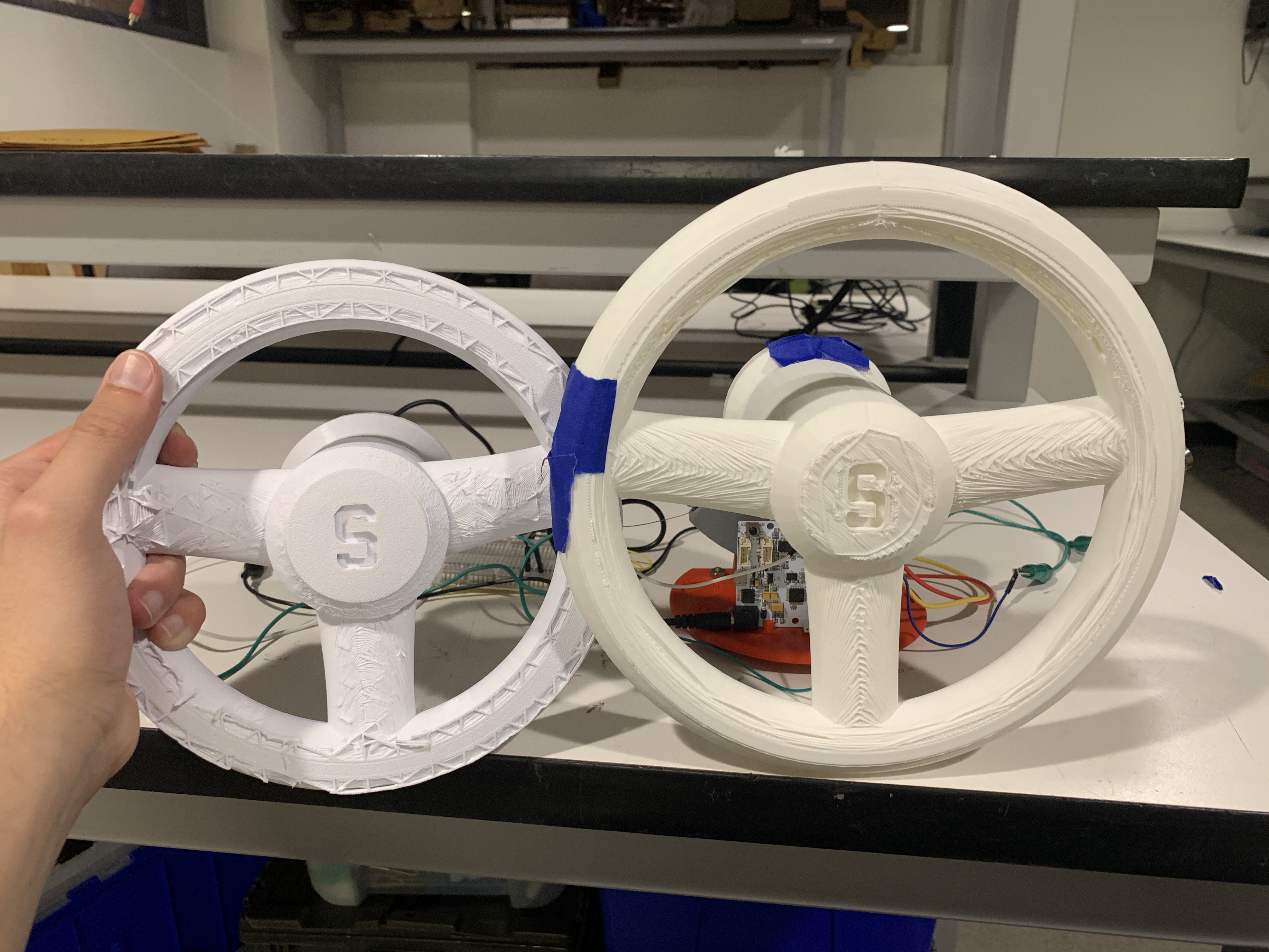
Initial Designs
After opting for a circular steering wheel over a yoke, we decided to reduce its size and weight in order to facilitate its integration with the Hapkit. We found that the larger steering wheel was too large and heavy, and lacked support when connected to the Hapkit due to its weight and long distance from the center. As a result, the final steering wheel used had a diameter of 8 inches and a shorter steering column than the initial design, bringing it as close as possible to the Hapkit connecting point. Additionally, a support clip was added to the back portion of the steering wheel to prevent it from tipping over.
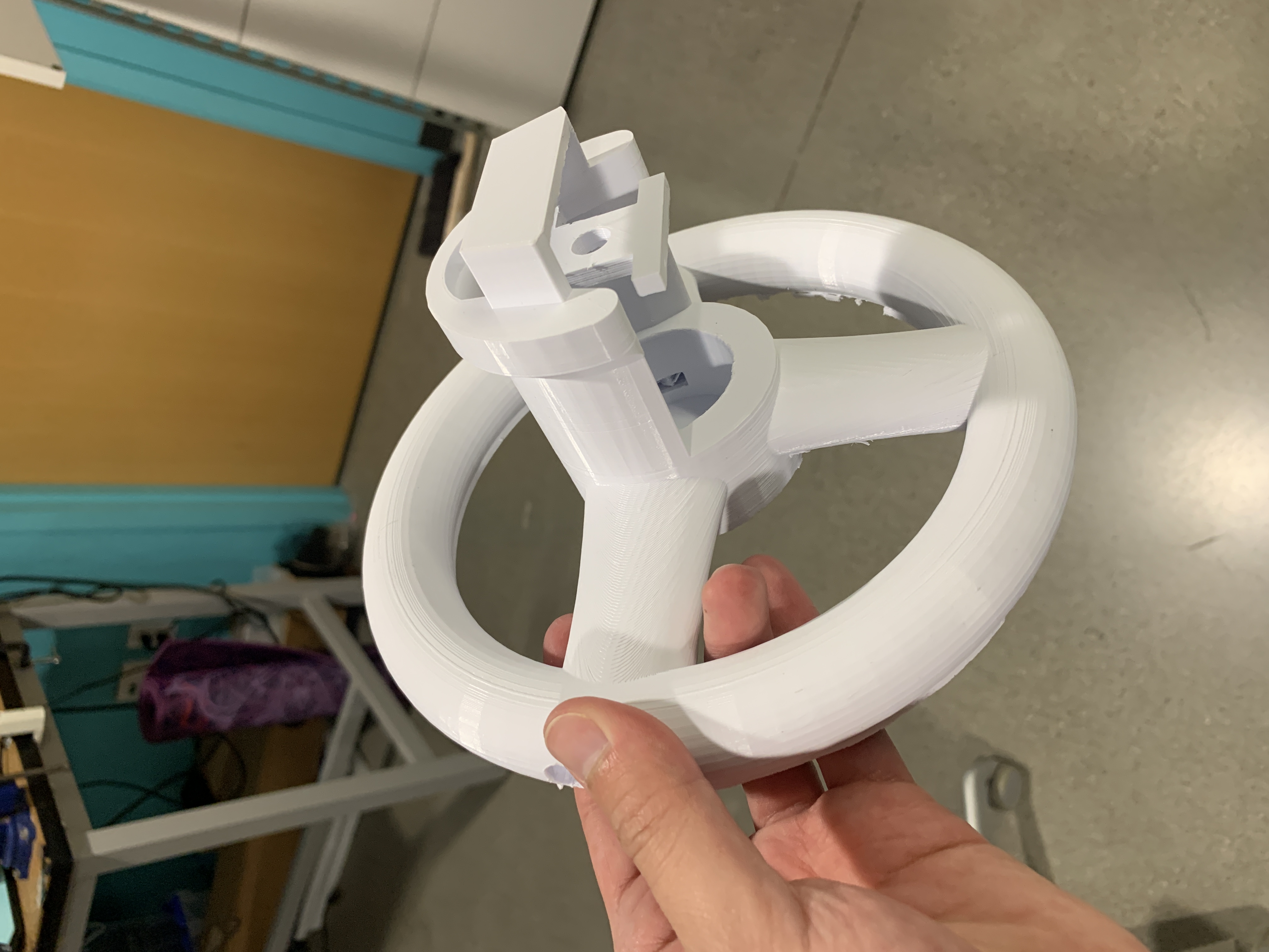
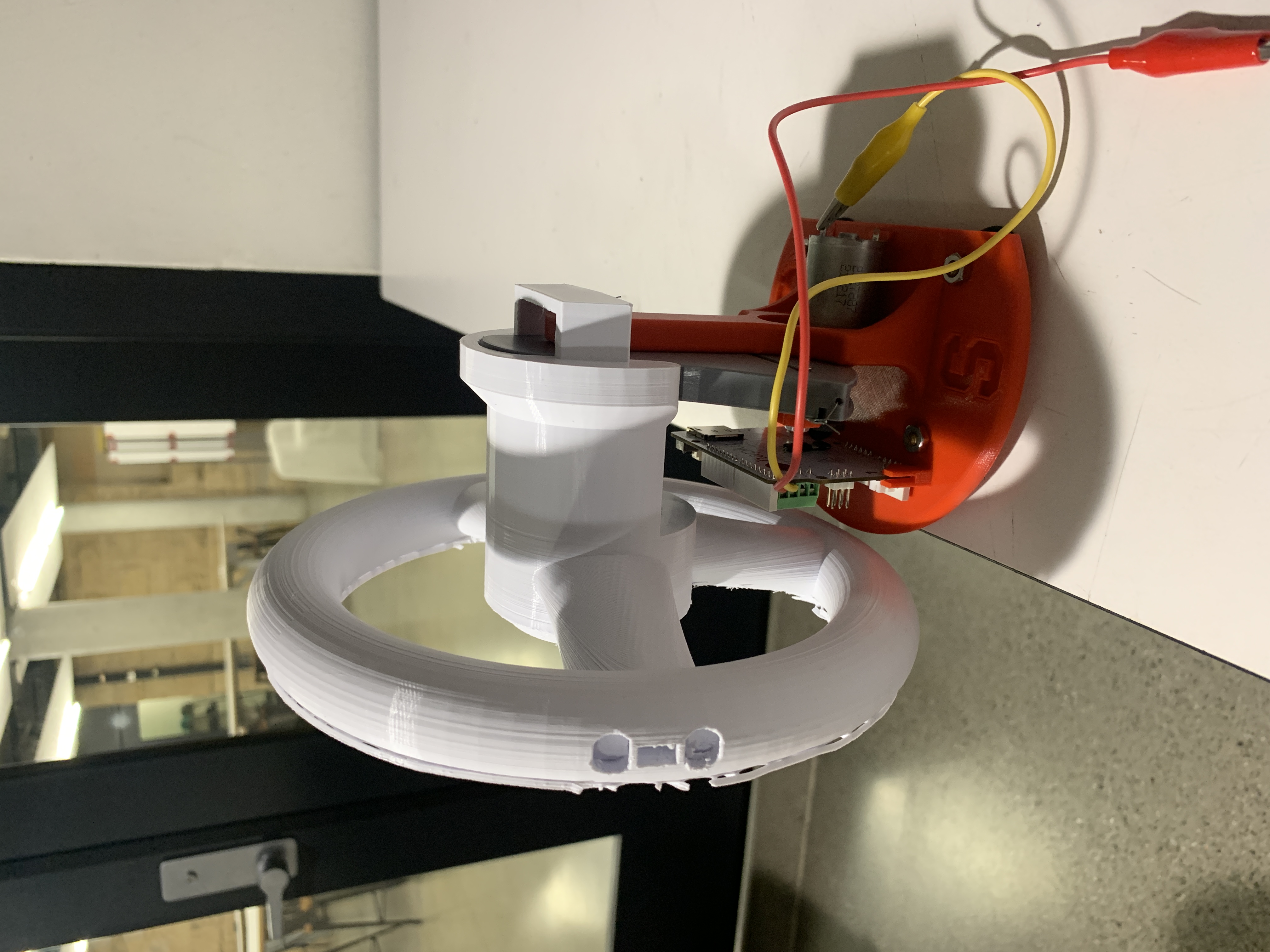
Final Design
Front view:
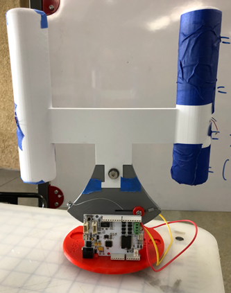
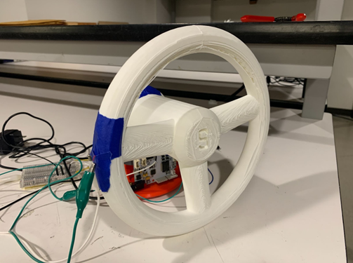
Rear view:

Assembly front:

Assembly rear:
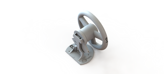
Rendering front:

Rendering rear:

CARLO (Python)
Our trials were conducted using a 2D driving simulator, CARLO [5]. CARLO stands for CARLA - low budget. It is a simulator that is less realistic than CARLA but much easier to configure and experiment with. It is also computationally lighter and can run on most computers without the need of advanced graphics cards. CARLO uses bicycle model dynamics based on "Kinematic and Dynamic Vehicle Models for Autonomous Driving Control Design" by Jason Kong, Mark Pfeiffer, Georg Schildbach, Francesco Borrelli [6].
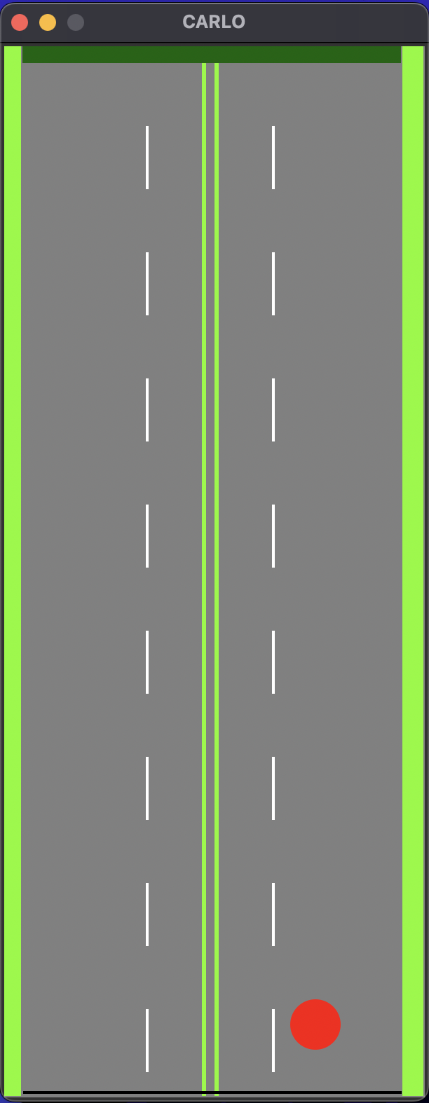
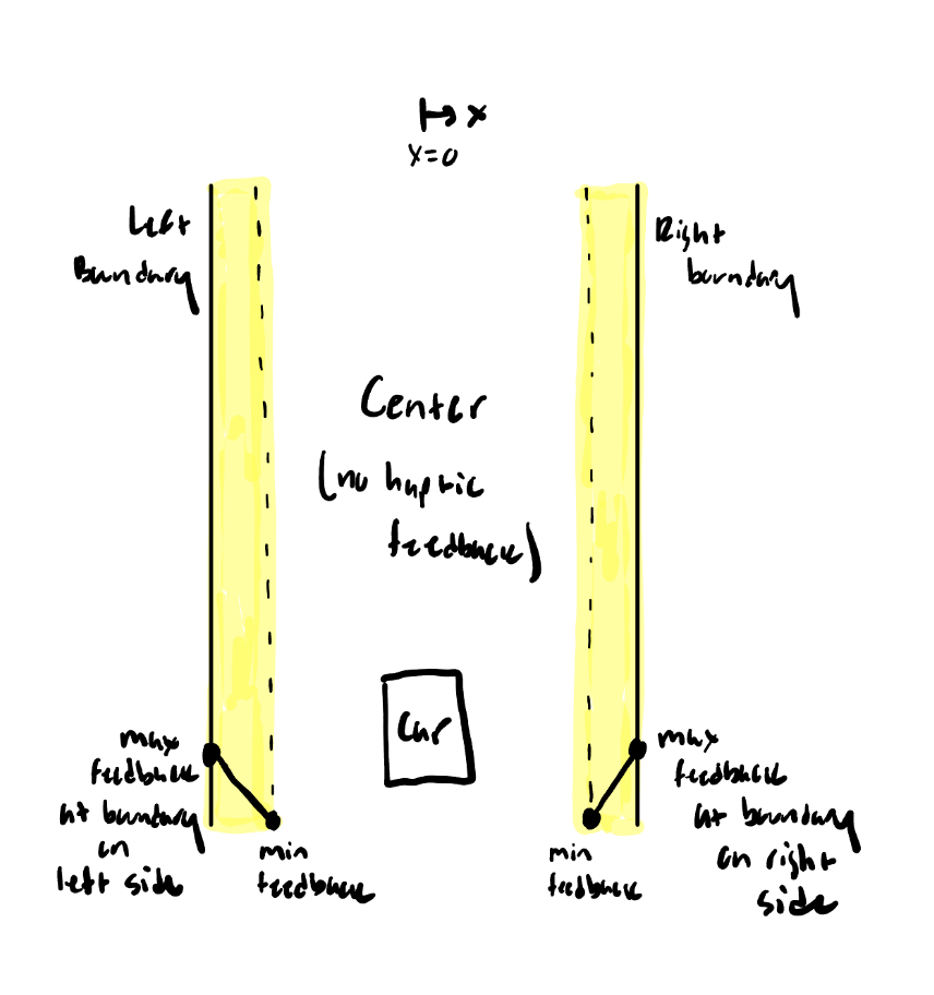
Our graphics consisted of a straight road with three lanes. The road is surrounded by grass on both sides filled in with a lawn green color. Due to the nature of lane centering, only one lane was required. However, adding two more lanes allowed for users to visually see if they departed from the lane and made rending the force and vibrational feedback easier as due to more virtual space. The center lane was divided into three sections. The vehicle was determined to be centered inside of the lane if the center of the vehicle was within the green zone shown in the image below. We refer to this region as the buffer zone. The buffer zone was only used for the rending of force and vibrational feedback. Additionally this zone was not shown to participants during the trials. The distance between the center of the lane and the position of the vehicle was labeled as the variable DEPTH. The MAX_DEPTH was defined as the horizontal distance between the white dashed lane and the center of the lane.
Once the vehicle and world was selected, input from the Arduino needed to be read and interpreted by the Python script. CARLO allows the programmer to select a steering angle for the vehicle. For our application we decided to map the position of the Hapkit handle to a steering angle. If the position was negative that corresponded to a steering angle that would turn the vehicle left, and if the position of the handle was positive that corresponded to a steering angle that would turn the vehicle right. The Python package PySerial was used for this communication.
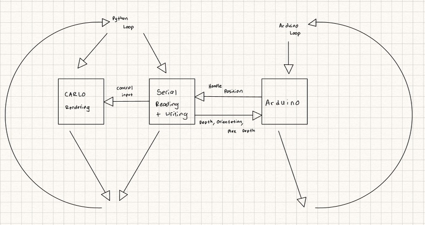
After implementing the PySerial Package, we noticed that there was a delay in the simulation graphics and the rate at which the Adurnio sent its data. Through experimentation it was determined that Python’s sequential method of executing code was slowing down the rate at which it can receive data. In order to solve this issue the Threading Python Package was used. The graphic rendering of CARLO was placed on one thread and the PySerial communication of reading and writing data was placed on a separate thread. This allowed both threads to run simultaneously and prevented interruption between threads. The Python script sends the following variables to the Arduino script: depth, orientation, and max depth. The max depth stays constant throughout the simulation but we decided to still send that variable over serial communication to make the code more robust.
The diagram below shows how the code runs.
Our initial study included 5 participants, and we determined there were changes to be made to improve the studies. We decided to change the vehicle from a rectangle to a circle. We found that this made centering in the lane more difficult because users could not see the orientation of the vehicle, which inhibited their visual feedback. We also added some road noise to make staying centered in the lane more difficult. Initially this was implemented as a random force to the steering wheel, but participants stated that it was difficult to distinguish between the road noise and the force feedback. We then implemented road noise as a random steering input to the steering of the vehicle in CARLO. CARLO made the world easy to manipulate and abstracted some of the pixel math needed in other simulators. We decided to experiment with the vehicle speed, lane width, center buffer zone size, and the starting position of the vehicle to make our experiment more controlled and also ensure that the haptic feedback “felt” comfortable to users.
Haptic Feedback (Arduino)
Vibrational Feedback
The first haptic feedback element we implemented was vibrational feedback. The overarching idea of the vibrational feedback is for the steering wheel to vibrate on the side corresponding to where the user begins to depart the lane. For example, a user beginning to depart the lane to the right would experience a vibration on the right side of the steering wheel, alerting them and allowing them to take corrective action. We opted to implement this vibrational feedback once the user exits the center buffer zone, giving them time to take corrective action before exiting the lane.
We experimented with two different methods of augmenting the vibrational feedback according to the vehicle’s distance from the edge of the lane, in order to convey the urgency of the feedback. We first tried a constant vibration, varying the intensity of the vibration linearly according to proximity to the edge of the lane. It was difficult to differentiate between vibration intensities with the vibration motors we were using, so we instead switched to varying the vibration pattern instead of the intensity. Our final vibrational feedback implementation starts with a slow pulsing vibration pattern when the vehicle leaves the buffer zone, with the pulse rate increasing linearly proportional to depth until the edge of the lane, at which point the pulse rate is held constant. The maximum pulse rate is limited due to the vibration motors used, while the minimum pulse rate was set such that it was rapid enough to still be recognized by the driver. Due to the relatively narrow width of the lane in the virtual world, it is difficult to distinguish between the different pulse rates. We anticipate that this issue could be resolved by experimenting with different types of vibration motors and implementing this system in a real vehicle, where the width of the lane is much larger.
Force Feedback
The second haptic feedback element that we implemented was an assistive force feedback. This force feedback is meant to provide a force to prevent the user from exiting the lane - however, we wanted to avoid making the force so large and intrusive that the driver is passive, rather than the driver actively using the haptic feedback to make adjustments. Our first force feedback implementation was a virtual wall on either side of the lane, starting at the edge of the buffer zone. This wall provides a force towards the center of the lane proportional to the distance from the edge of the buffer zone. However, in experimentation we determined that the virtual wall can cause oscillations due to the corrective force acting even when the user was already headed towards the center of the lane.
Due to this oscillation, we designed a second assistive force feedback system that eliminates the undesired oscillations. This force feedback system applies a force proportional to the vehicle orientation, once the vehicle exits the buffer zone headed towards the edge of the lane. For example, a user beginning to depart the lane to the right would experience a force to the left proportional to the vehicle orientation. This force helps restore the vehicle orientation to zero degrees (straight forward), which in turn prevents the user from exiting the lane. Through testing, we found that this method of force feedback helps prevent the user from exiting the lane, without pushing them past the centerline and causing oscillations such as those experienced with the first form of force feedback.
Experimental Design
Our study consisted of three separate trials in which the user was asked to drive the vehicle into the center lane from the starting position and attempt to stay centered within the lane. The three trials are as follows:
- Trial 1: No haptic feedback
- Trial 2: Vibrational feedback
- Trial 3: Vibrational and force feedback
The user was briefed on how to interpret the two different haptic signals and it was explained to them that they would see small amounts of drifting of the vehicle along the road, representing road noise. These trials were presented in a random order to each user to limit the effect of learning from successive trials in our collected data. The user was also not told in advance which of the three trials they would be doing. From preliminary testing we noticed that when this was disclosed to the user they would purposefully run into the left and right boundaries of the lane to experience the haptic feedback, skewing their performance metrics.
We collected quantitative and qualitative data from 20 Stanford students and affiliates on Demo Day. For each user we computed their average distance from the center of the lane and their average absolute orientation, providing two metrics to quantify the performance of the user. The qualitative data was collected from a Google Survey asking a series of multiple choice and short-answer questions related to how the user felt using the haptic-assisted steering wheel compared to the baseline (no haptics) as they drove along the straight road. The user was asked to fill out this form after they had completed the three trials and had been informed which order they did the trials in.
Overall, the goal of the study was to assess the effectiveness, from both a performance and a user perspective, of haptic feedback on the steering wheel to help drivers stay centered within the lane.
Setup on demo day:
Video: https://drive.google.com/file/d/1XVdwZEQIGQgUHSHSkA3Q-RMoC8slv-vr/view?usp=sharing
Results
Two scoring metrics were used to compare performance across trials. The first metric calculated the average absolute distance from the center of the lane to the vehicle's position. A lower value meant that the user stayed closer to the center and thus had more optimal driving performance. The second metric calculated the average absolute orientation of the vehicle. The orientation was defined as 0 degrees when the vehicle was oriented parallel to the road. A positive orientation meant the vehicle was oriented to the right and a negative steering angle meant the vehicle was oriented to the left. The lower the average absolute orientation was, the less erratic the vehicle’s behavior was. Below is the data from 20 participants:
| Average Distance from Center | Standard Deviation | Average Orientation Magnitude | Standard Deviation | |
|---|---|---|---|---|
| Trial 1 | 1.594 | 0.387 | 14.189 | 3.144 |
| Trial 2 | 1.597 | 0.537 | 14.314 | 4.725 |
| Trial 3 | 1.556 | 0.535 | 13.315 | 3.315 |

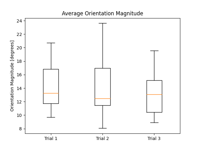
As shown above the averages between the different trials are all comparable. Participants were able to stay centered on the lane best with vibrational and force feedback, however this trial also had a higher standard deviation. Participants were also able to keep an orientation closer to 0 with vibrational and force feedback. While this may suggest that vibrational and force feedback leads to more optimal driving performance, the differences are not statistically significant.
The qualitative results present a clear conclusion on what participants believed helped them stay centered on the lane. The majority of participants stated that trial 2 and trial 3 felt easier to keep the vehicle centered and prevent the vehicle from exiting the lane. Additionally participants said they believed vibrational and force feedback would be most helpful if they were distracted. This finding is interesting because quantitative results show participants did better with no feedback than vibrational feedback. Pie charts showing the results are presented below:
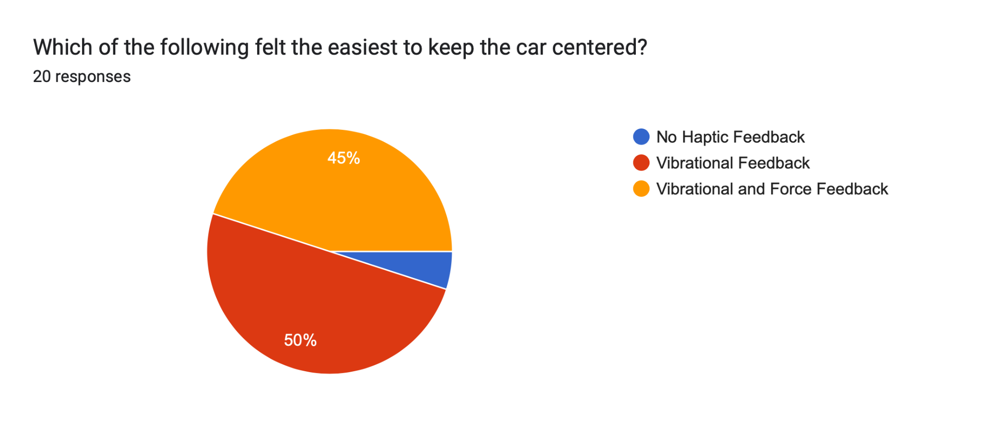
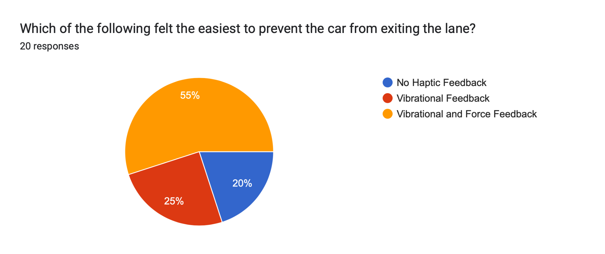
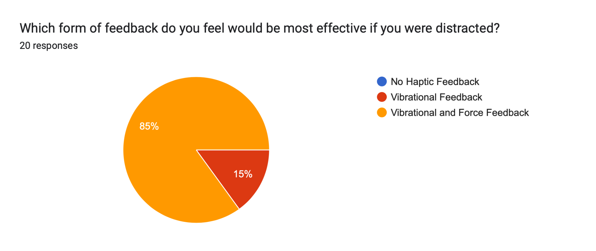
Overall, it is clear that participants felt vibrational and force feedback helped keep the vehicle centered within the lane. However, quantitative results show that there was no significant difference in performance.
Future Work
For future work, we looked into the feedback provided by the study participants as well as other areas of potential improvement that may result in an improved lane assistance experience.
One issue we faced during implementation of the vibrotactile feedback was that vibration intensity would drop significantly as the frequency of vibrations was increased, regardless of duty cycle. This, as a result, made it difficult to provide the user with a gradual increase in vibration frequency while maintaining vibration intensity as they moved further away from the center of the lane. In the future, we plan to look into using higher quality vibration motors that will allow us to achieve strong and rapid vibration patterns.
Additionally, it may be useful to expand this study to more complex road environments, such as a curved or circular road. This would allow us to test the effect of the haptic feedback in different scenarios that are typically faced when driving a vehicle on a road. Additionally, doing this study on more complex roads may allow us to eliminate the road noise in order to focus more on the effect of the haptic feedback. These new environments will add more complexity to the haptic feedback algorithms, but will provide further insight into the effectiveness of haptic feedback on driving performance.
Lastly, a few users that participated in this study mentioned that they would be interested in trying a scenario which only provided them with force feedback with no vibrational feedback - this additional scenario can be included in a future study.
Acknowledgments
We would like to express our sincere appreciation to the class teaching assistants who helped us make improvements to our project in various OH sessions over the course of these last three weeks and to our demo participants who allowed us to draw meaningful insights from our study. We couldn’t have done it without your help!
Files
All code is available in the following repository: https://github.com/jerryalvarez/ME327.
CAD Files: https://drive.google.com/drive/folders/1B0o7ZD1knI54Y7NX_rJMIc9QV__cYXPS?usp=sharing
Bill of materials: https://docs.google.com/spreadsheets/d/1xGJtjAZSoDZebYVMNgbDOgantpjGeShSv9hryyodrXM/edit?usp=sharing
References
- Consumer Reports. (n.d.). Lane departure warning and lane keeping assist: A guide. Retrieved from https://www.consumerreports.org/cars/car-safety/lane-departure-warning-lane-keeping-assist-guide-a7087080070/
- Gaffary, Y., & Lécuyer, A. (2018). The use of haptic and tactile information in the car to improve driving safety: A review of current technologies. Frontiers in ICT, 5, 5. https://doi.org/10.3389/fict.2018.00005
- Beruscha, F., Augsburg, K. and Manstetten, D., 2011. Haptic warning signals at the steering wheel: A literature survey regarding lane departure warning systems (short paper).https://digital.lib.washington.edu/researchworks/bitstream/handle/1773/34898/he-v5n1.pdf?sequence=1&isAllowed=y
- Onimaru, S. I., & Kitazaki, M. (2010, March). Visual and tactile information to improve drivers' performance. In 2010 IEEE Virtual Reality Conference (VR) (pp. 295-296). IEEE. https://doi.org/10.1109/VR.2010.5444759
- Cao, Zhangjie, et al. “Reinforcement Learning Based Control of Imitative Policies for Near-Accident Driving.” Robotics: Science and Systems XVI, 2020, https://doi.org/10.15607/rss.2020.xvi.039.
- J. Kong, M. Pfeiffer, G. Schildbach and F. Borrelli, "Kinematic and dynamic vehicle models for autonomous driving control design," 2015 IEEE Intelligent Vehicles Symposium (IV), Seoul, Korea (South), 2015, pp. 1094-1099, https://doi.org/10.1109/IVS.2015.7225830.
Appendix: Project Checkpoints
Checkpoint 1
Initial Project Checkpoint Goals
CARLO
- Setup GitHub
- Create a basic road with three lanes (One lane will be the driving lane and there will be an additional lane on either side)
- Create functions to alert for lane departure
- Establish communication from Python script to Arduino script using PySerial
- Establish communication from Arduino script to Python script using PySerial
- Use our current Hapkit handle to control the vehicle’s steering in CARLO
- Left turns the vehicle to the left and right turns the vehicle to the right
Steering Wheel
- Design steering wheel using CAD
- Ensure it fits our current Hapkit
- Include indentations for multiple vibration motors
- Print wheel and ensure correct alignment
Vibration Motors
- Investigate what size/spec will work for this project and the number of motors needed
- Coordinate with the steering wheel designer to discuss vibration motor specifications and dimensions - Will the vibration motors provided for our previous HW be sufficient? Is one on either side sufficient or are more needed?
- Plan the power supply needed to power all the motors
- Will the Arduino supply enough power for all the motors? Will we need an additional power supply unit?
—--------------------
Current Progress
We are making some changes to the scope of our project based on suggestions provided from our proposal. We had mentioned we would provide vibration feedback to the left or right side of the steering wheel upon making contact with the left or right lane. Rather than waiting for the vehicle to make contact with the boundaries of the lane we are deciding to provide feedback earlier such that the driver is able to make the necessary adjustments earlier. The idea is to use vibration and force feedback that is proportional to the driver’s proximity to the lane’s boundaries. Our project serves as a lane-centering haptic device on top of acting as a lane departure warning system.
CARLO Simulation / Graphics: Please reference https://github.com/jerryalvarez/ME327 for all the code.
The world created is a road going in one direction. It has three lanes in which the car will be centered in the middle one. The goal of the project will be attempting to keep the car centered in the middle lane. Please see the image below for the rendering of our world.
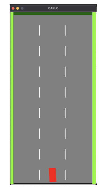
The red square is our vehicle and the light green markings are the side of the road. A helper function was created to return a boolean variable that says whether the car has hit a lane. The next step was communication between the Python script and the Arduino. The PySerial module was used for this bidirectional communication. We initially only had one-way communication between the two programs and were unsure why the bidirectional communication was not working. After further investigation, it was discovered that the rending algorithm for CARLO was taking significantly longer than the speed at which the serial communication was operating at and this created issues when running both programs at the same time. After consultation with Conner, he suggested we look into multiprocessing or multithreading. Multithreading was used and the rending algorithm was conducted in one thread and the serial communication was conducted in another thread. This solved the issue of timing and allowed us to have bidirectional communication. Once we had bidirectional communication, the ME 327 Hapkit was used to send its position information to the Python script. If the handle was to the left of the centerline, the steering of the car would change to be left and if the handle was to the right of the centerline, the steering of the car would change to be right.
Steering Wheel:
We decided to prototype two different steering wheel designs - one standard (circular) steering wheel and one yoke steering wheel. The thinking behind this is that the yoke steering wheel creates more separation between the positions where the two hands contact the steering wheel, potentially making it easier to determine which vibration motor is activated (left vs. right). However, the circular steering wheel might be more familiar to the user and easier to turn. The difference in performance between the two steering wheels will be determined through testing.
For the circular steering wheel, it was designed to be significantly smaller than a standard car steering wheel, but large enough for the user to comfortably grip each side. The diameter was chosen to be around 8 inches. At each side of the steering wheel, two circular indentations were created to house the vibration motors, and two inner channels were cut extruded through the longitudinal structures. These channels will be used to channel the wires through them to the steering column. The wheel connects to the bottom sector of the hapkit through a steering column.

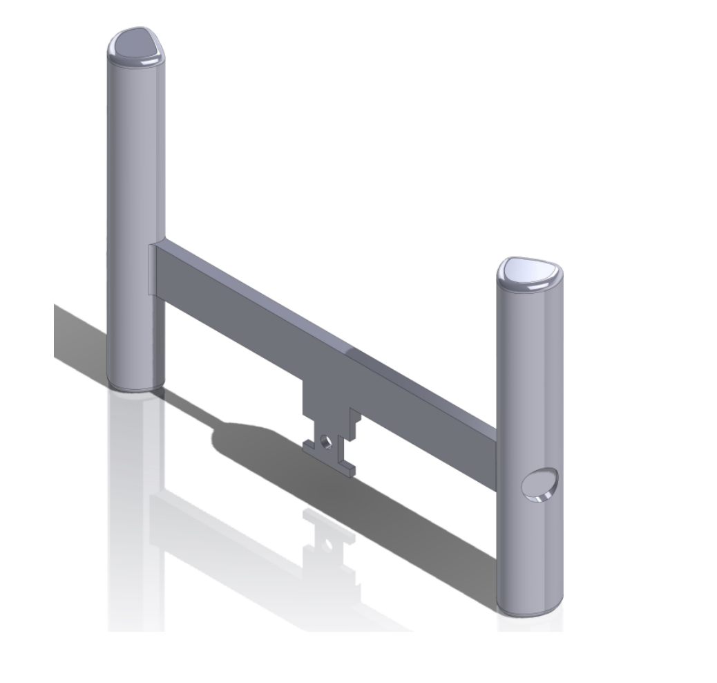
For the yoke steering wheel, we used SolidWorks to construct a simple yoke steering wheel with a crossbar that interfaces with the current hapkit setup, and two vertical handles for the user to hold onto. The vibration motors will be placed in recesses near the point of contact with the hands. For this prototype, we provided two recesses on each side - one near where the palm contacts the steering wheel and one near where the fingers contact. We will determine whether either recess alone, or the two in combination, result in a more compelling vibration warning. If we opt to go with the yoke design, we will further refine the contours of the handles to make them more ergonomic and better accommodate the vibration motors. The CAD for the yoke steering wheel is provided below for reference:

The 3D printing for the yoke steering wheel is done and has been integrated into the Hapkit assembly as shown above. The circular steering wheel is in the process of being 3D printed and will be done on 5/26. During OH Dane brought up a good point that applying an adequate force becomes more difficult with larger steering wheels. This is something we’ll have to experiment with and we’ll make future iterations of our design smaller if needed.
Vibration/Force Feedback:
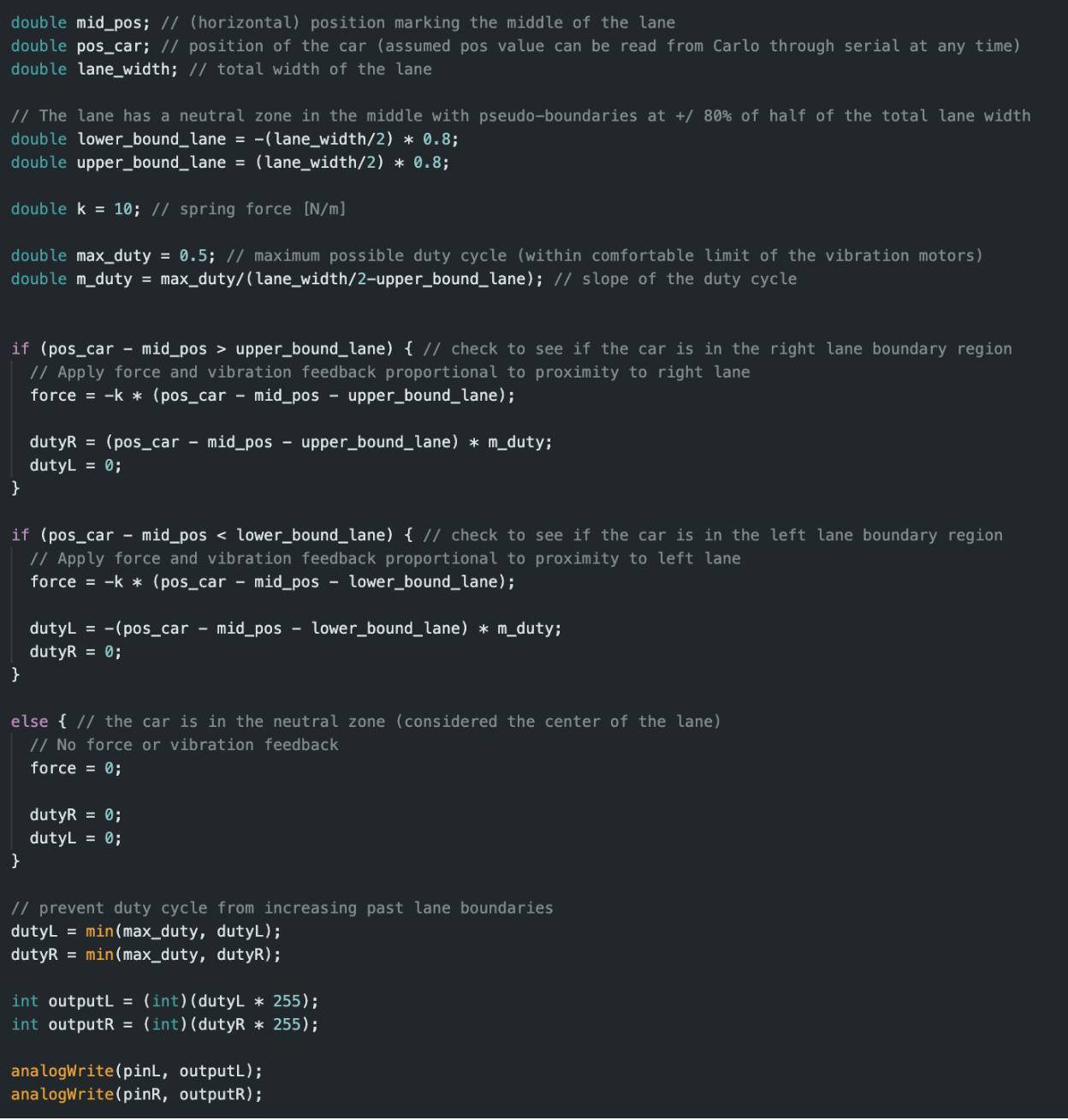
We have written an Arduino script that applies vibration and force feedback to the steering wheel. The lane is divided into three regions: a neutral region in the center of the lane where no feedback is applied, and two regions on the left and right side where feedback is provided that is proportional to the driver’s proximity to the lane’s extreme left and right boundaries. This is accomplished by applying a restorative spring force proportional to the penetration distance into the boundary and using a linear equation for the vibration profile where the max duty cycle is equal to 0.5 at the lane’s extreme left and right boundaries.
This code will be tested on 5/26 with the yoke steering wheel configuration shown in the previous section. Based on our findings we will make any necessary adjustments to our force and vibration profiles. During preliminary testing of the vibration motor on the default hapkit parts, we determined that the provided vibration motors will be sufficient to provide a vibration warning through the 3D printed steering wheel.
Checkpoint 2
Initial Checkpoint Goals
CARLO
- Implement vehicle control using 3D printed steering wheel
- Implement basic vibration motor pattern when lane departure is detected
Steering Wheel
- Refine for user comfort
Vibration Motors
- Plan the vibration motor wiring from the steering wheel to the Hapkit
- Coordinate with steering wheel designer
- Explore and investigate the vibration motor effect that will be used
- Pattern - what pattern will we use to inform users of lane departure?
- Duration - how long will the motor be on? When will they be turned off? (when the vehicle is centered on the lane or when corrective action is detected?)
- Duty Cycle/Amplitude - how powerful will the effect be? Will it progressively get stronger/weaker?
—--------------------
Current Progress
We are making some changes to the scope of our project based on suggestions provided from our proposal. We had mentioned we would provide vibration feedback to the left or right side of the steering wheel upon making contact with the left or right lane. Rather than waiting for the vehicle to make contact with the boundaries of the lane we are deciding to provide feedback earlier such that the driver is able to make the necessary adjustments earlier. The idea is to use vibration and force feedback that is proportional to the driver’s proximity to the lane’s boundaries. Our project serves as a lane-centering haptic device on top of acting as a lane departure warning system.
CARLO Simulation / Graphics:
Please reference https://github.com/jerryalvarez/ME327 for all the code.
With most of the CARLO milestones completed, we focused on integrating the simulation with the hardware. Using the steering wheel, we were able to control the direction of the vehicle in CARLO while also providing the user with vibrational and force feedback. The steering wheel is still being modified but we hope to finish it within 48 hours. Once the final steering wheel is completed, it will be installed and we will hyper tune our parameters to ensure the best feeling for the user. An export function was also implemented in the code. This function exports the x position of the vehicle over time to demonstrate the performance of staying within a lane. The function also plots this data to display.
Steering Wheel:
After testing both types of steering wheels printed, we decided to go with the circular steering wheel. The reasoning behind that was that our testing determined that there was no issue in using a circular steering wheel when it comes to feeling the separate vibrations on each side. While there is some minimal vibration leakage through the steering wheel to the other side, this was barely noticeable and it was quite obvious which side the vibration was coming from. Additionally, the circular steering wheel felt more natural from a user perspective, and the yoke steering wheel did not completely eliminate vibration transfer from side to side either.
Initially, we opted for a large steering wheel, as shown in the previous checkpoint, with a long steering column to strive for an experience as close as possible to a real steering wheel. However, we found that this steering wheel was too large for comfort, heavy, and lacked support when connected to the hapkit due to its weight and long distance from the center.
As a result of this, we redesigned the steering wheel to make it smaller in diameter, and we significantly shortened the steering column to bring it as close as possible to the hapkit. Furthermore, a support tab was added to the back of the steering wheel to prevent it from pulling down on the hapkit sector and to provide support. These changes proved to be very successful at improving the experience and made the steering wheel experience great.
Vibration/Force Feedback:
We spent a significant amount of time experimenting with different vibration intensities and patterns to achieve the desired sensation for the user. Our first implementation was a constant vibration that increased in intensity as the user approached the edge of the lane. We found it very difficult to distinguish between different duty cycles within the small operational range of the vibration motors, so we decided to instead use varying patterns. The first pattern tested starts off with a slow pulsing vibration after passing some threshold while approaching the edge of the lane, with the pulse rate increasing as the user approaches the edge of the lane and becoming constant after crossing the edge of the lane. However, we found that if the pattern crossed a certain timing threshold (became too rapid), the vibration intensity decreased significantly. Therefore, our final implementation varies the pulsing pattern between a lower limit and an upper limit when approaching the edge of the lane, and outputs a constant vibration once the edge of the lane is reached.
For force feedback, we implemented a force proportional to how far the vehicle is into the ‘threshold zone’, which is the area approaching the edge of the lane. This essentially acts as a spring, which pushes the user back towards the center of the lane. We experimented with different stiffness values, as we don’t want the experience to feel like autonomous driving - we simply want a force that will alert the user to take corrective action. We settled on a stiffness that provides a noticeable tug to the steering wheel, without autonomously steering the vehicle back into the center of the lane.
Alongside the force feedback, we also are going to try to implement ‘road noise’ using the motor, which takes the form of small random forces that the user must counter. This prevents the user from simply keeping the steering wheel centered at all times without any adjustment, and makes the experience more realistic by simulating the small bumps that a real vehicle faces while driving.