

2023-Group 9

Naviband
Augmented sensing beyond vision.
Naviband: A navigation headband providing real-time orientation feedback through stereo vibration
Project team member(s): Alvin Sun, Kai Liang, Wanyu Weng, Yifan Guo
The project aims to develop a haptic-based guidance system to enhance the independence and mobility of visually impaired individuals in navigating different environments. Recognizing the limitations of existing assistive technologies, the team developed a wearable headband that integrates eight vibrotactile disc motors to provide cutaneous feedback based on direction commands. The device can cover a full range of direction-steering for the user and the user's orientation can be live updated via a 9 DOF IMU. The system can be teleoperated through the interface via the ESP32 board.
On this page... (hide)
Introduction
Visual impairment presents significant challenges in terms of perceiving and interacting with the surrounding environment, leading to limitations in independence and mobility. In response to these challenges, our team developed a haptic-based guidance system, featuring a wearable headband integrated with vibration motors that provide cutaneous feedback in multiple directions. It taps into the heightened sense of touch often experienced by visually impaired individuals, enabling them to gather information and navigate unfamiliar environments more effectively. By implementing this navigation system, this project can provide visually impaired individuals with a comprehensive and versatile solution that addresses their specific needs and enhances their overall mobility experience.
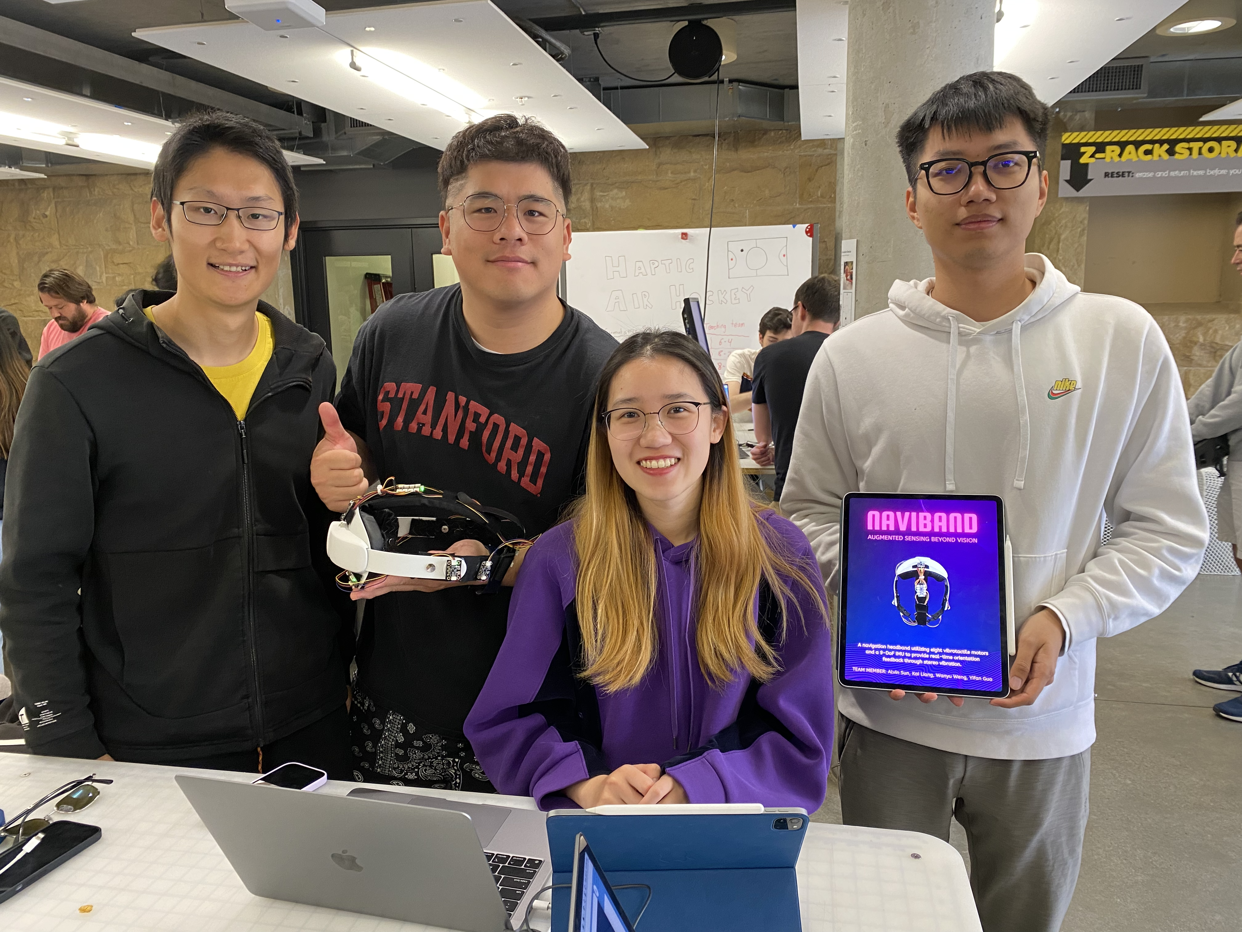
Project team members: Alvin Sun, Yifan Guo, Wanyu Weng, Kai Liang (left to right)
Background
Navigation plays a crucial role in our daily lives, enabling us to explore and navigate through various environments effortlessly. However, visual impairment presents significant challenges in terms of perceiving and interacting with the surrounding environment, leading to limitations in independence and mobility. A bulk of research has been done by scientists on non-vibration techniques in haptic navigation systems to aid blind individuals in navigation. Tactile interfaces, such as touchscreens and tactile maps, have been researched to represent paths, obstacles, and landmarks relying on pressure and texture cues. Ottink et al. [1] examined cognitive map formation and navigational abilities in visually impaired and sighted individuals, finding that both groups performed equally well in forming accurate cognitive maps and utilizing similar navigational strategies when presented with a tactile map of a city-like environment. Hofmann et al. [2] developed a tool, Maptimizer, that generates customized tactile maps to assist individuals with visual impairments, using an optimization process to enhance clarity and improve the identification of locations of interest. Additionally, auditory feedback, such as special technology, has also been employed to provide directional cues and alerts. Salih et al. [3] investigated the prioritization and selection of natural sounds and auditory cues of visually impaired individuals in unfamiliar environments, highlighting the need for standardized design and on-demand minimal audio feedback to enhance mobility and independence for people with visual impairments. Scalvini et al. [4] presented a novel navigation device that utilizes visual-auditory substitution and visual markers to provide visually impaired individuals with 2D spatial sound perception, enabling safe indoor navigation by detecting obstacles and determining the shortest path to a desired destination. While these non-vibration techniques have shown promise, they often have limitations in conveying real-time information and precise spatial details, hindering their effectiveness in dynamic environments.
In recent years, vibration feedback haptic navigation has been researched extensively to address the shortcomings of non-vibration methods. Several studies have demonstrated the efficacy of vibration feedback in enhancing spatial perception and object recognition for visually impaired individuals. Vibrotactile cues can effectively guide users along predefined paths, warn them about obstacles, and provide intuitive directional cues. Sun et al. [5] introduced Haptic Compass, a prototype device that utilizes real-time vibrotactile feedback to provide directional cues for haptic guidance, demonstrating its effectiveness in enhancing task performance and user experience for visually impaired individuals in small dimensional space. Liao et al. [6] presented a promising approach to guide individuals using multidirectional vibrotactile feedback (MVF), exploiting Phantom Tactile Sensation (PTS) to achieve directional resolution with limited vibration motors. The use of wearable haptic devices, such as wearable tactile belts or handheld devices, allows for the transmission of navigational information through varying patterns and intensities of vibrations. Oliveira et al. [7] introduced a vibrotactile head-mounted display for spatial awareness in 3D spaces, exploring optimal frequency modulation modes and the placement of vibration motors on the forehead. It revealed the high sensation of the forehead to vibrations and recommends using tactile displays with a low actuator density, conveying different target elevation information by different frequencies. Quick et al. [8] designed a wearable haptic wristband, the OptiBand, providing vibrotactile information about both nearby and distant objects for blind individuals. It validated the feasibility and potential applications in the field of wearable robotic systems and assistive devices.
Despite the promising advances in vibration feedback haptic navigation, there are certain limitations that need to be addressed. One challenge is the accurate and sensitive interpretation of different vibration patterns, which may require extensive training or customization. To overcome it, a comprehensive and appropriate protocol can be established to help with training. Additionally, the design of compact and wearable haptic devices that offer sufficient vibratory cues while maintaining user comfort remains an ongoing challenge. As per the experiment results of Pacchierotti�s team [9], although the forearm was the most comfortable location to wear the haptic device, it has less efficiency in haptic cue detection than on the forehead. Furthermore, the development of robust algorithms and techniques to generate real-time vibration feedback based on environmental cues and user interactions is still an area of active research.
Methods
Hardware design and implementation
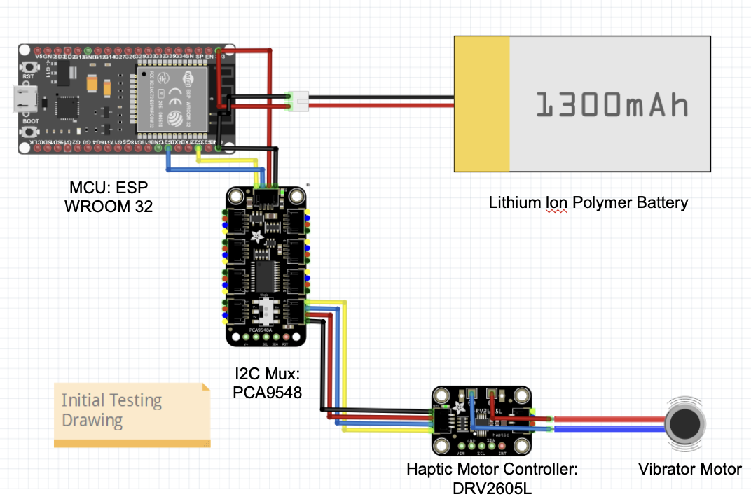
During the hardware design process, the team first started with designing and evaluating the performance of the major components that are essential for the haptic device system. Specific components, such as the vibrator disc motor, the DRV2605L board (motor driver), an 8-channel multiplexer, an ESP32 microcontroller, and a battery, were integrated for a single-motor functionality test, as shown below. Specifically, the ESP32 board supports a Wi-Fi module, providing wireless communications for easier device control.
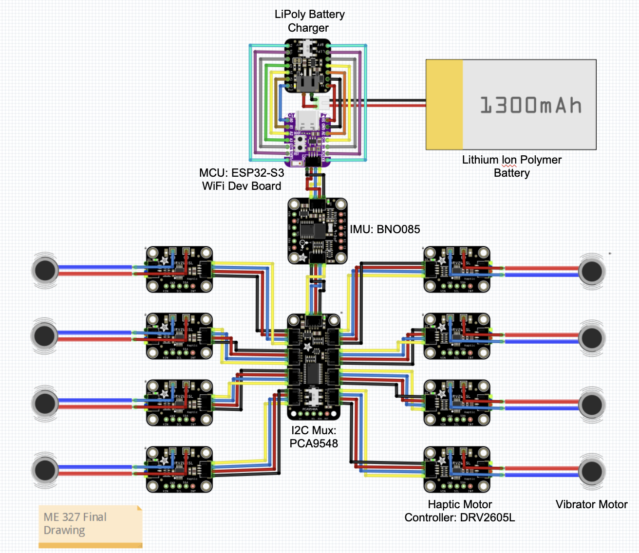
During the final construction phase, additional seven sets of vibrator disc motors and motor drivers were integrated. The system was also modified using a smaller ESP32 board, resulting in a more compact and integrated design. In addition, a 9-DOF orientation Inertial Measurement Unit (IMU) was integrated into the system to introduce a new user orientation real-time tracking feature. The complete electronic connection diagram can be referenced below.
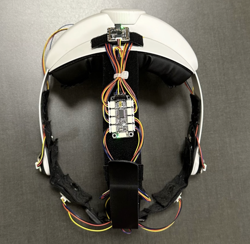
The final design of the Naviband incorporated an adjustable VR headset strap and an elastic front head strap with all the electronics together. Eight vibrotactile disc motors were placed around the headband at angles of 0�, �50�, �90�, �150, and 180�. The motor drivers were mounted on the outer side of the head strap connecting to the multiplexer located on the center of the top strap. The IMU was mounted on the backside of the head pad. All the wires were organized to align with the strap and additional lengths were placed inside the head pad along with the battery and ESP32 module. All the electronics were mounted to the headband with Velcro for easy installation and replacement. On top of each motor, eight rectangular shape cushions with a hole in the middle were placed on top of the motor to ensure direct contact between the motor and the user�s skin and at the same time providing a more comfortable experience while wearing.
The headband was adjustable through the knob on the back to accommodate different head shapes and the head pad and strap utilized memory foam and Faux leather to improve the user�s experience.
Software Development
Stereo Vibration Control
Since DRV2605L has a fixed I2C address, it was necessary to use an I2C mux to select between the different motor driver boards to achieve individual control of multiple vibration motors.
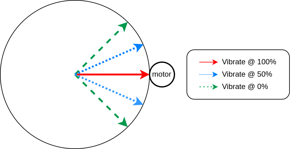
Directional vibration feedback was achieved through linear interpolation on vibration amplitude between adjacent motors. Each motor was associated with a pre-calibrated mounting angle, and it would vibrate the strongest when the target direction was set to be the same as its mounting angle. The vibration amplitude of each motor linearly fades off within a fixed range centered around its mounting location. Shown below is an illustration of how a single motor will respond to different orientation targets.
Orientation Sensing
The goal was to extract the absolute yaw angle of the user orientation. It can be computed using the quaternion readout from the BNO085 IMU sensor. BNO085 was a 9-DoF IMU with the built-in fusion between the three inertia sensors, which can directly output global 3D orientation in quaternion format. However, since we cannot mount the IMU strictly upright, we needed to compute some coordinate transformation to achieve the yaw angle extraction.
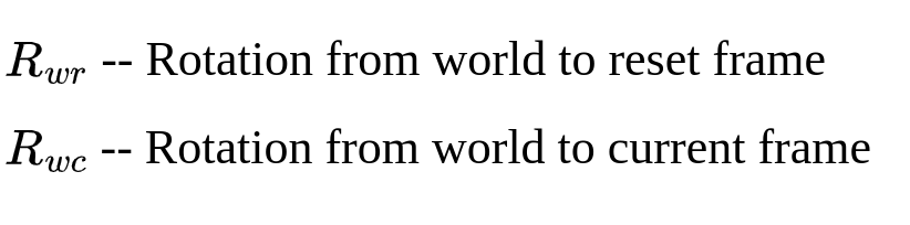
During startup (or requested from our control interface), an orientation reset happens by recording the reset rotation. Later during inference, we can read out the current orientation from the IMU. We define the rotations read directly from IMU as follows
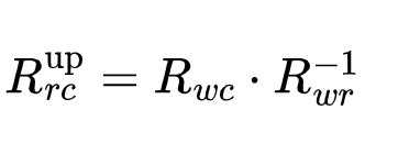
We can then compose the current orientation with the inverse of the reset orientation to obtain another quaternion that describes the rotation from the reset frame to the current frame in a z-up coordinate.
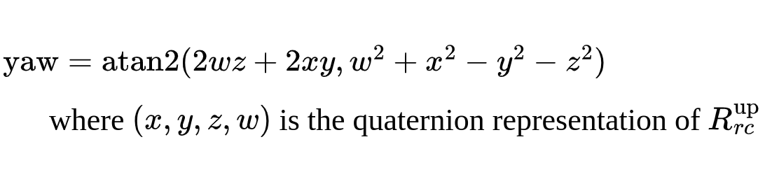
Finally, we can extract the yaw angle using the following equation
User interface
The user interface was designed via Processing. As depicted in the figure, the interface contains two main modules: the live orientation info module and the information display module.
The live orientation module consists of a fixed, 360-degree orientation reference with 5-degree resolution. Within the reference, there is a rotatable compass that provides real-time orientation information of the tester based on data provided by the IMU. The red dot on the compass represents the forward direction in which the user is pointing, and this forward direction can be reset according to different environment conditions and users� preferences. The communication between the microcontroller and the host GUI is through WiFi, where the ESP32 MCU hosts a server and a WiFi access point while the Processing code implements a client that connects to the server. The user angle data measured on the MCU is being continuously streamed to the Processing client while Processing sends data back to the MCU only when the following events occur. By moving the pointer and clicking on a specific location on the reference circle, the host can select a desired angle or direction. Once the desired angle is chosen, the corresponding location will be highlighted, and a vibration motor will be activated, providing live feedback to the user. The user will then be able to adjust the head to align with the desired angle based on the haptic feedback. Once the set target is approached and user�s orientation is within +/- 8 degrees of the desired angle, the red dot will turn green, indicating a successfully reach.
On the right side of the interface, the information module displays additional details, the desired angle will be shown on the bottom once it was highlighted on the reference circle. the interface also displays the time taken to locate the target successfully. The �current user angle error� is continuously updated, showing the offset between the user�s forward direction and the desired direction in real time.
Experiment procedure
Two experimental activities were conducted with each participant under conditions of closed eyes. Before the tests, calibration was provided to each user to allow for any necessary adjustments in the orientation of the haptic device. Through the calibration, the testing individual was able to compare their real-time orientation with the desired orientation provided in the user interface. The first experiment aimed to determine how quickly the participants could identify a randomly selected orientation of vibration. To complete the task, participants needed to identify the orientation within 8 degrees of the correct orientation. Each individual performed a total of three tests, during which their reaction time and detection errors were recorded for further analysis. The second activity involved walking along a path by following the vibration guidance from the haptic device. One of the team members guided each participant to follow one of three pre-marked paths on the ground. Further analysis of the testing results was discussed in the result section.
Results
- When trying to locate the angle in the range of -90� to 90�, tested people demonstrated a faster average response time with smaller navigation error.
- When locating desired angle beyond 90� and -90�, tested people were relatively slower in finding the target and a large error was observed.
- There existed some outliers in which tested people were not able to locate the desired angle within the pre-set tolerance range (+-8�). Those data was filled with 20s of response time and were not taken into account towards the average accuracy.
- Through learning and calibration, most people demonstrated a faster response time and better accuracy after the first time they tried the headband on.
- Through qualitative testing and feedback, the Navi band is comfortable to wear and the vibration level is within the comfort range of most participants.
- Through the activity of walking the path, the Navi band showed great potential to guide participants for a long distance, as most participants showed great completion in the task.
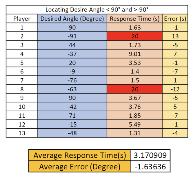
Desired angle locating time and error (<=90 degrees), red-highlighted: outlier
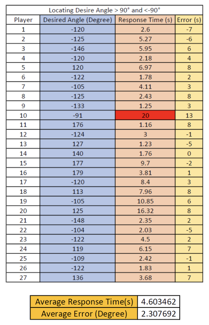
Desired angle locating time and error (>90 degrees), red-highlighted: outlier
Future Work
After conducting extensive testings within the team members and to public during the Open House Day Demo, it was found that the current configuration of the haptic device has faced a communication instability issue. Upon reviewing the user manual and online forum, it is believed that the BNO08x I2C implementation violates the I2C protocol in some circumstances. This causes it not to work well with certain chip families. As a result, it is necessary to integrate a more reliable communication into the system for future development.
It is also essential to address the limitation of the current haptic devices. The current design only provides directional information to the user as guidance, however, there are more important aspects in real-time guidance application, particularly for visually impaired individuals, elevation information plays an important role in real-world guidance in assisting slope detection and increasing environment awareness. In the future, the system can be improved by incorporating elevation guidance, utilizing different vibration frequencies to indicate varying elevations
Additionally, multiple optical cameras can be integrated to the haptic device to track user�s real-time position and provide more accurate feedback in assisting navigation.
Files
Code can be found on GitHub
References
[1] Ottink, L., van Raalte, B., Doeller, C. F., Van der Geest, T. M., & Van Wezel, R. J. A. (2022). Cognitive map formation through tactile map navigation in visually impaired and sighted persons. Retrieved from https://www.nature.com/articles/s41598-022-15858-4
[2] Hofmann, M., Mack, K., Birchfield, J., Cao, J., Hughes, A. G., Kurpad, S., � Mankoff, J. (2022). Maptimizer: Using optimization to tailor tactile maps to users needs. CHI Conference on Human Factors in Computing Systems, 1�15. doi:10.1145/3491102.3517436
[3] Bilal Salih, H. E., Takeda, K., Kobayashi, H., Kakizawa, T., Kawamoto, M., & Zempo, K. (2022). Use of auditory cues and other strategies as sources of spatial information for people with visual impairment when navigating unfamiliar environments. International Journal of Environmental Research and Public Health, 19(6), 3151. doi:10.3390/ijerph19063151
[4] Scalvini, F., Bordeau, C., Ambard, M., Migniot, C., Argon, S., & Dubois, J. (2022). Visual-auditory substitution device for indoor navigation based on fast visual marker detection. 2022 16th International Conference on Signal-Image Technology & Internet-Based Systems (SITIS), 259�266. doi:10.1109/sitis57111.2022.00029
[5] Sun, M., He, W., Zhang, L., Wang, P., Wang, S., & Bai, X. (2019). Haptic Compass: Active vibrotactile feedback of physical object for path guidance. 2019 IEEE Conference on Virtual Reality and 3D User Interfaces (VR), 1171�1172. doi:10.1109/vr.2019.8797956
[6] Liao, Z., Luces, J. V., & Hirata, Y. (2020). Human navigation using phantom tactile sensation based vibrotactile feedback. IEEE Robotics and Automation Letters, 5(4), 5732�5739. doi:10.1109/lra.2020.3010447
[7] de Jesus Oliveira, V. A., Brayda, L., Nedel, L., & Maciel, A. (2017). Designing a vibrotactile head-mounted display for spatial awareness in 3D spaces. IEEE Transactions on Visualization and Computer Graphics, 23(4), 1409�1417. doi:10.1109/tvcg.2017.2657238
[8] Quick, R., Bontula, A., Puente, K., & Fitter, N. T. (2022). Retrieved from https://project.inria.fr/phrc2022icra/files/2022/06/ICRA2022_Workshop_Quick.pdf
[9] Kuang, L., Aggravi, M., Giordano, P. R., & Pacchierotti, C. (2022). Wearable cutaneous device for applying position/location haptic feedback in navigation applications. 2022 IEEE Haptics Symposium (HAPTICS), 1�6. doi:10.1109/haptics52432.2022.9765619
Appendix: Project Checkpoints
Checkpoint 1
Checkpoint1 goals:
- Complete the coding and programming for the motor control software;
- Make the initial hardware setup of the haptic headband.
Current hardware process
In the past week, the team made a Bill of Materials (BOM) and ordered all the necessary items for our project, which can be found in the File section's Major components with costs.
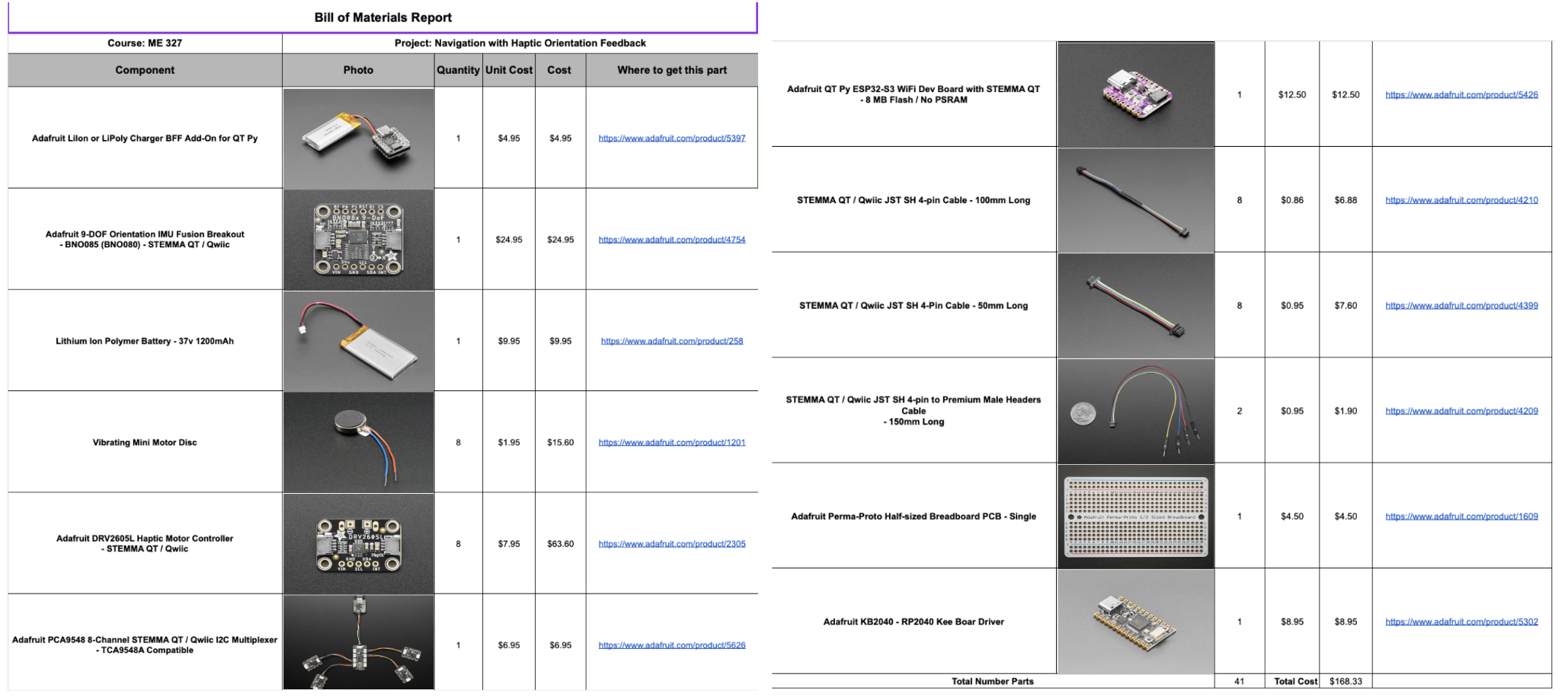
Bill of Materials
The team has developed a simplified physical wearable hand strap that incorporates essential modules into its design. The controller board, power module, and wire integration module are conveniently placed on the back side of the head strap as shown below. The team had integrated 8 vibration motors along the inner side of the headband, each spaced 50 degrees apart. Additionally, LEDs are attached to the outer side of the head strap, corresponding to the location of each motor.
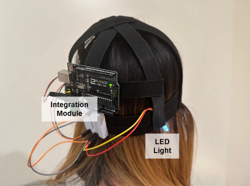
initial setup mounted on head (Alpha prototype)
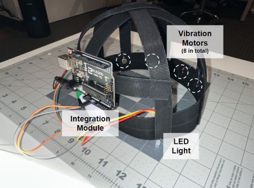
Alpha prototype with dimensional description
The head strap itself is crafted using Velcro, ensuring adjustable sizing to cater to the diverse needs of different users. As we progress towards Checkpoint 2, we plan to include more specific controller modules, IMU modules, and Wi-Fi/Bluetooth modules into our design.
Current software process
As we are still waiting on the other hardware materials to arrive, the software on oriented vibration control is completed and can be seen in our GitHub codebase. The control API works for an arbitrary number of motors. It takes in a direction angle and turns on the vibration motor(s) that are closest to this direction. Directions that are in between two motors are currently handled with linear interpolation.

motor control
Checkpoint 2
Checkpoint1 goals:
- Build a Beta Prototype and implement IMU to measure orientation and output vibration feedback;
- Design the demo activity and develop the Processing graphics.
1. Build a Beta Prototype and implement IMU to measure orientation and output vibration feedback;
After conducting tests on the Alpha prototype, the team has achieved success in developing a Beta prototype. The Beta prototype incorporates elements from both the GoPro head strap and VR kit with vibration motor and board attached as shown in Figure 1. The primary focus during the design process was to ensure maximum comfort when wearing the haptic device. To achieve this, careful consideration was given to the design, ensuring that the only contact surface between the prototype and the human head is the vibration motors shown in Figure 2, rather than the potentially sharp control board. Furthermore, the team has decided to put the rest of the hardwares such as battery, control board inside the VR Kit unit to support the weight to ensure the maximum comfortness for the users as shown in Figure 3. Finally, Team member tested and verified the comfort of the prototype shown in Figure 4. In addition, the team has completed the coding parts for the IMU and waiting for the hardware shipment.
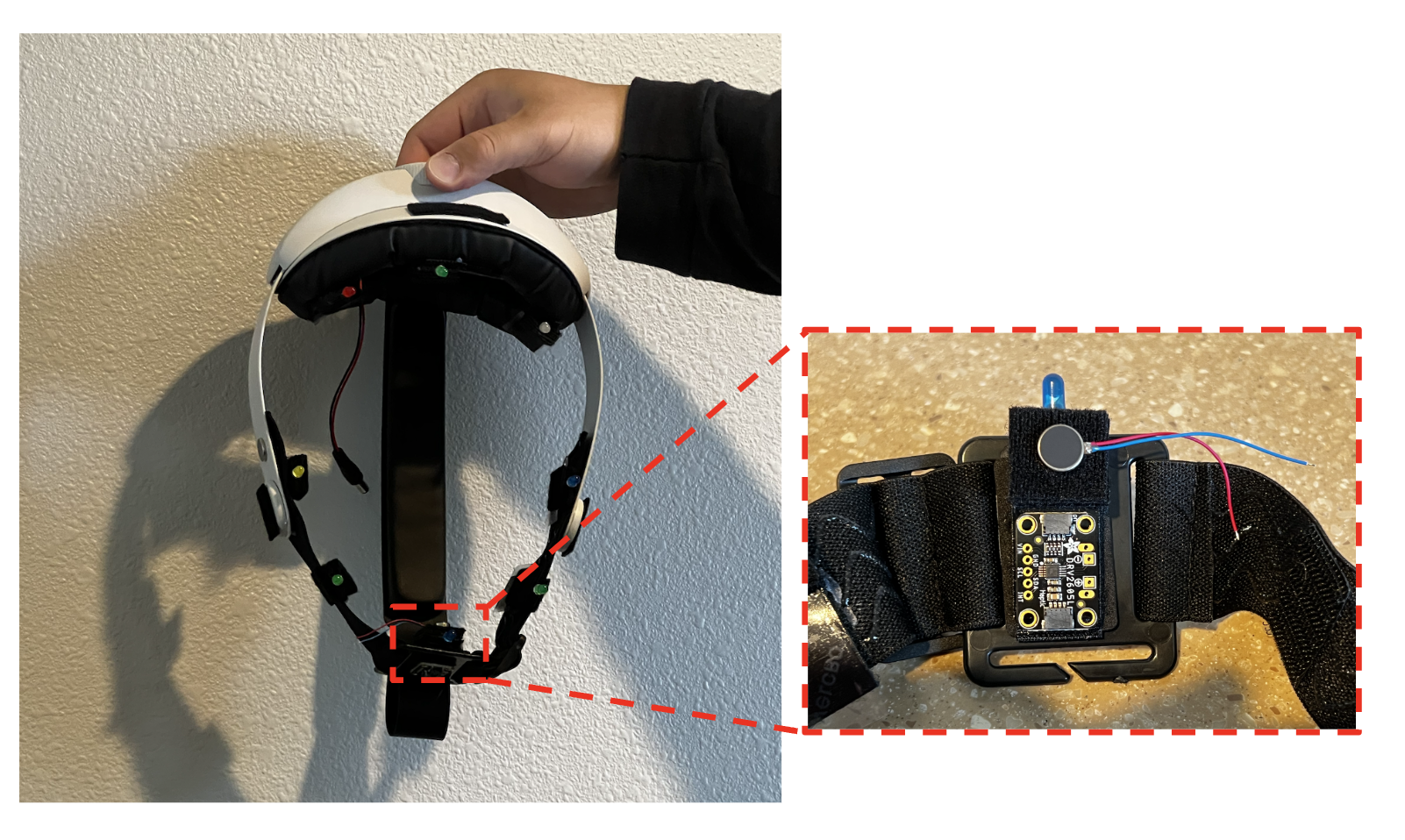
Figure 1: Beta Prototype
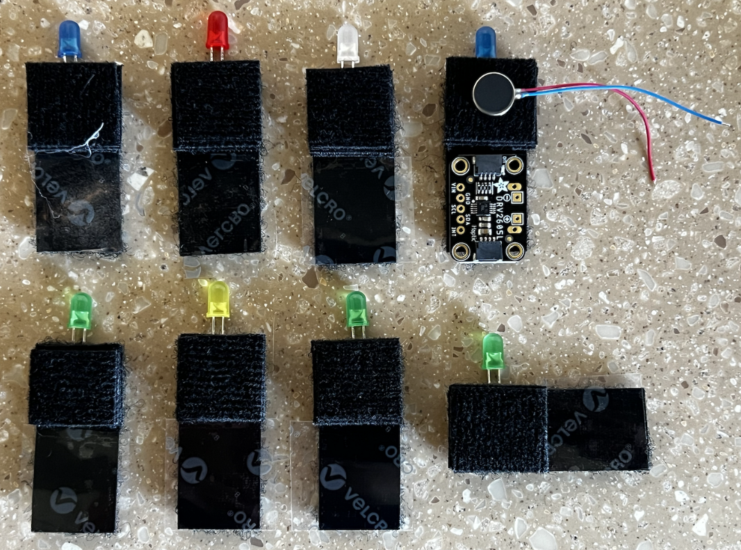
Figure 2: Design of the mounting of the vibration motor board
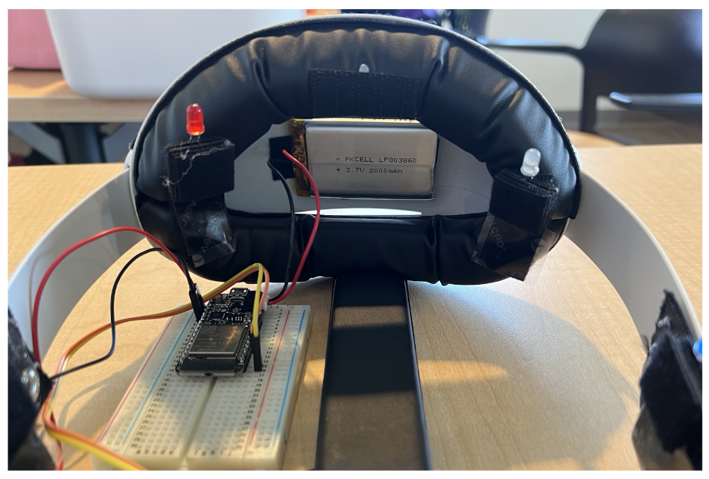
Figure 3: Placement of the main hardware components
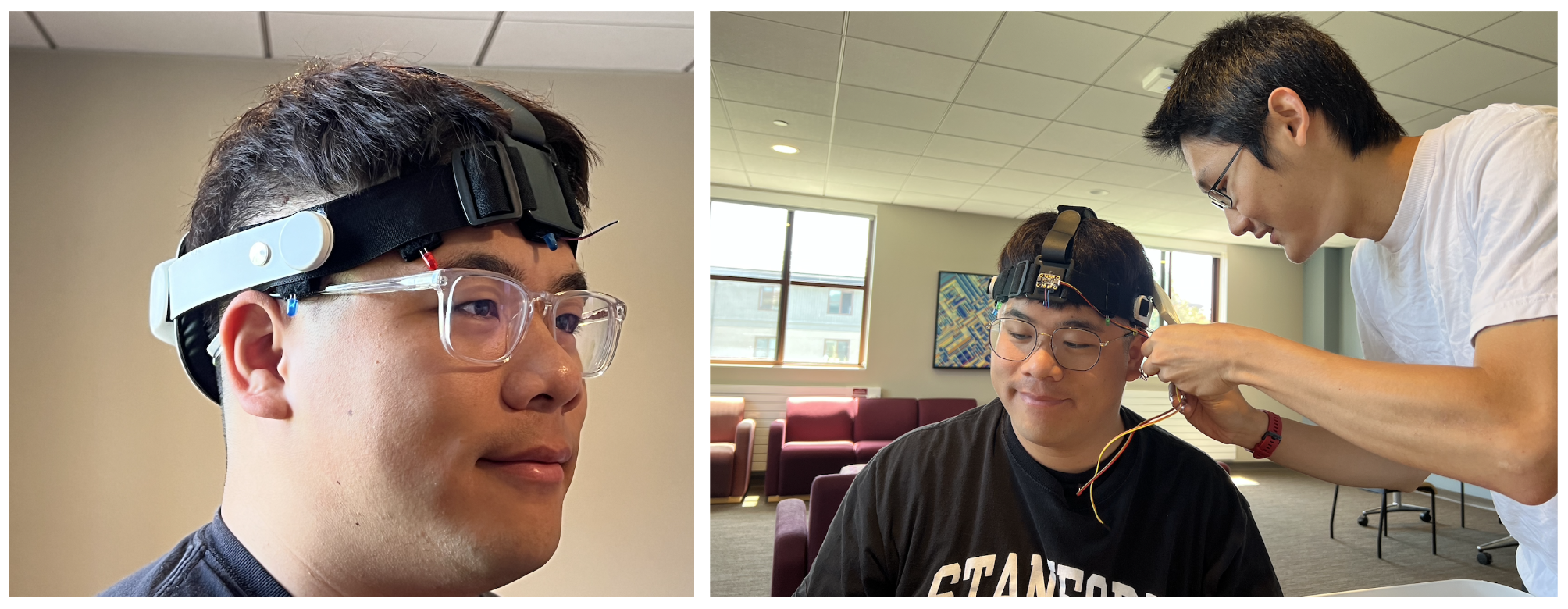
Figure 4: Team member testing the comfort of the prototype
2. Design the demo activity and develop the Processing graphics
The team has additionally created a demo activity for students to experience during the Open House Day. Our team members have developed corresponding graphics using Processing. Figure 5, displayed below, illustrates the interface that enables the experimenter to set a specific angle. By utilizing the left and right arrow keys on the keyboard, directional information is transmitted to the user through the WIFI module built in the prototype. Furthermore, to enhance visualization for experimenters, the real-time orientation of the user is displayed through a flashing red dot on the screen. This feature provides experimenters with a clearer and more immediate representation of the user's orientation during the activity.
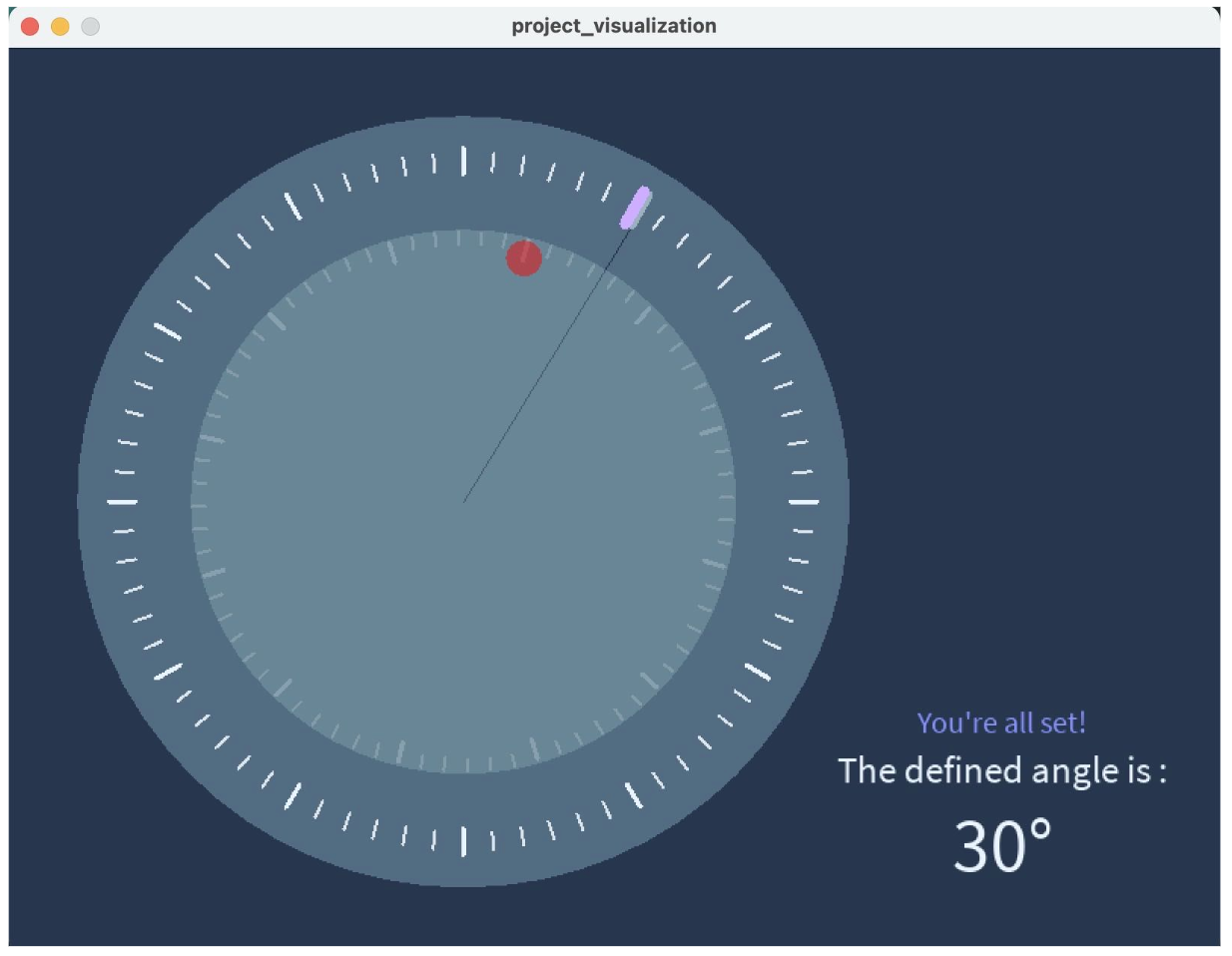
Figure 5: Project Visualization Interface
Unfortunately, there has been a significant delay in the shipment, and it is now expected to be delivered on June 2nd. As a result, the remaining hardware components cannot be installed in the haptic device at this time. Consequently, the team was unable to test the functionality of the 9-DOF Orientation IMU. However, there is a silver lining as the team was able to borrow an ESP32-S3 WiFi Dev Board, allowing us to complete the WIFI communication code using Processing. Despite facing this setback, the team maintains a positive outlook and is optimistic about their ability to finalize the hardware installation and conduct the necessary testing during the Open House Day due to the fact that the symmetry of the final prototype and the compatibility of the existing code, which allows for a streamlined process and increased efficiency in completing the remaining tasks.