

2024-Group 12

Group 12 with the Haptic Vest on Demo Day
Haptic Vest for Posture Alignment
Project team member(s): Sohun Patel, Shenandoah Wrobel, Edward Diller, Thomas Sounack
Back pain affects roughly 65 million Americans today and is the single leading cause of disability worldwide. One of the best ways we can prevent chronic back pain is to exercise good posture. In this project, we developed a posture alignment vest that helps users correct their posture. Our goal was to explore how effective we could be in using minimal haptic feedback to nudge users towards a healthy posture throughout their day. Using two Inertial Measurement Units and two vibration motors, the vest provides haptic feedback proportional to the spinal column bending angle and the chest angle with respect to the floor. The lightweight, vibration-based vest effectively alerts users when their posture is out of alignment and guides them towards a better position using intuitive spring-based mechanics. We are very happy with our final design and feel that we were able to create a valuable proof of concept that we could envision being used on a regular basis.
On this page... (hide)
Introduction
The motivation for this project is to develop a device that helps users improve their posture, to mitigate and prevent back pain. Given that many people have poor proprioception, or ability to sense their body’s position and movement accurately, we thought it best to incorporate haptic feedback into our design. Haptic feedback is particularly advantageous for this task as it is easy for humans to interpret, leading to a faster feedback loop for users. Using a vest enables an easy tracking of the spinal column’s position, while enabling direct tactile feedback with vibration motors on the chest.
Background
Prior works in the posture correction space contain a wide variety of methods for measuring posture, including video computer analysis, strain sensors, inclinometer sensors, accelerometers, electrogoniometers, inertial measurement units (IMUs) and more. We also observed a variety of feedback mechanisms depending on the specific use case, including vibrational motors and buzzers [1, 2], as well as actuated devices [3]. The applications of devices also range from general persistent posture feedback to task-specific training. We found that the biggest source of variance across these works was the feedback triggering methods. For example, one paper insists on providing feedback after a 42% flexion threshold is reached based on the user’s calibration [2]. Notably, we did not see any papers using any control-based feedback systems that vary the strength or nature of the haptic feedback based on the flexion over time.
Methods
Hardware Design and Implementation
To help measure the state of a user’s posture, we considered using a variety of sensors. From previous work, we had seen that gyroscopes, accelerometers, and vision-based systems with cameras had been used to observe posture, but we ultimately decided to use Inertial Measurement Units (IMUs), which come equipped with a gyroscope, accelerometer, and sometimes a magnetometer. They can directly measure triaxial rotation and triaxial acceleration of a body. The specific IMUs we chose were the Adafruit BNO055s since they are low cost, low power, and compatible with a helpful Arduino library that readily provides us the absolute orientation of a body about all three of its axes without us having to integrate gyroscope data. The library also provides functions to calibrate the sensors in the IMUs to remedy against sensor drift over time.
For the posture measurement, we placed 2 IMUs on the upper and lower back where we measure the forward and backward pitch, or tilt, of the sensors to determine the state of a user’s posture. We define poor posture as occurring in two ways:
- Upper back is curved relative to the lower back and does not maintain the same angle. The entire back is not flat.
- Upper back is bent too far forward about the hip, even if the back is straight.
To detect for the first case, we take the relative difference of the measurements by subtracting the lower back angle of tilt from the upper back angle of tilt. If this difference is positive and larger than 1°, this means that the user is curving their upper back too far forwards and needs to straighten it back to fall under the threshold. If the difference is negative and smaller than -3°, the user is curving their upper back too far backward and needs to straighten it.
To detect the second case of poor posture, we use only the upper back’s pitch measurement. Even with a straight back, if the user has bent over more than 50° from the straight-up good posture position, then the user has bent over too far and must correct their posture.
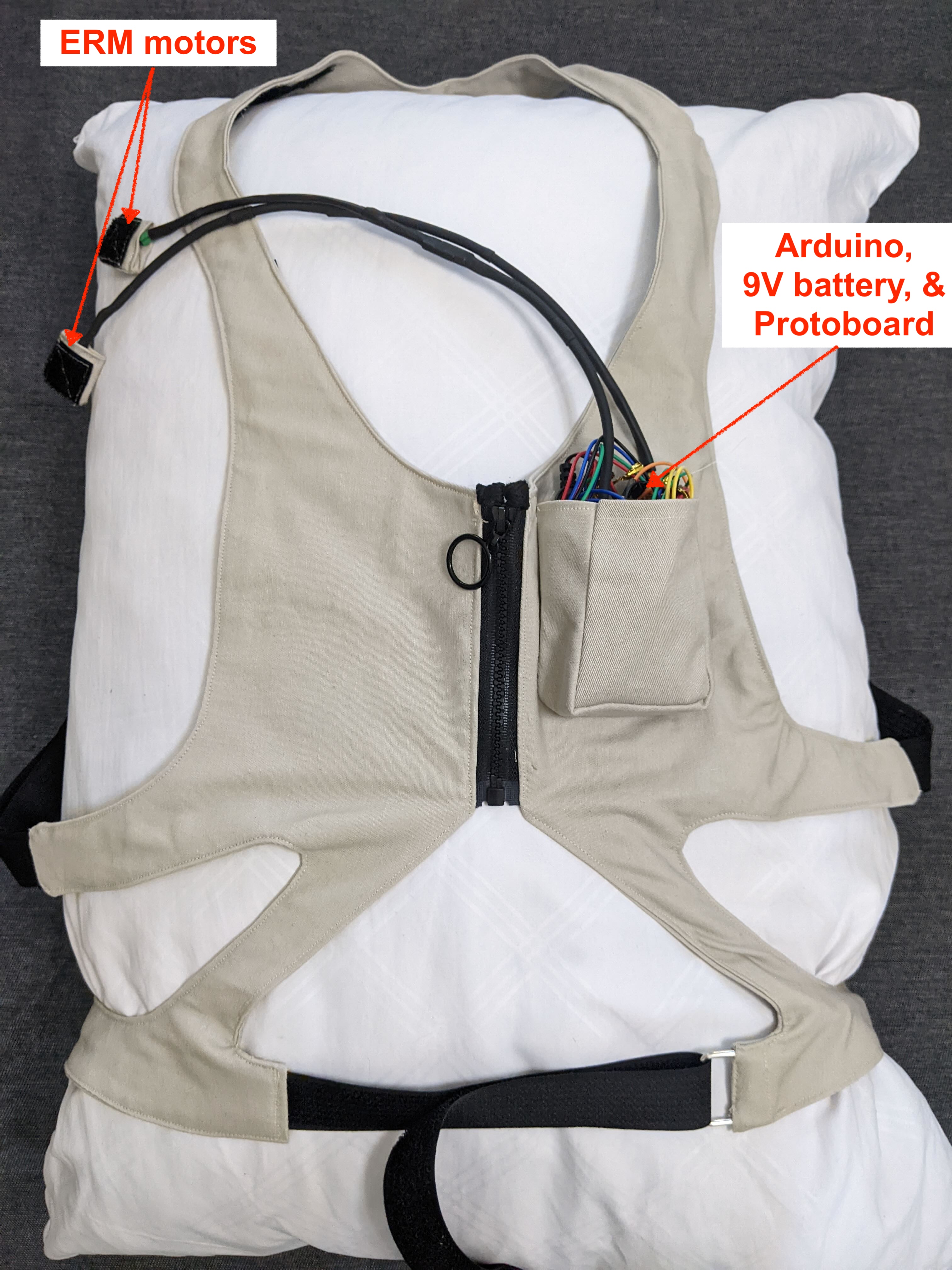
Haptic feedback is provided to the user via two eccentric rotating mass (ERM) motors. One is placed on the front of the vest near the user’s chest, and the other is placed on the vest near the upper back of the user. If the user’s upper back is curved too far forward relative to the lower back, the front ERM is activated. The amplitude of its vibration is proportional to the magnitude of the relative difference between the upper and lower back angles, once this difference is larger than the minimum threshold. A similar proportional vibration feedback is applied to the back ERM for the case when the upper back is curved too far backward relative to the lower back. When the user’s back is bent forward past the absolute limit, both ERMs activate and buzz at the largest amplitude until the user corrects their tilt to fall below the maximum tilt threshold.
We use an Arduino Uno to gather live sensor data through I2C communication protocol. Both IMU sensors share the same SCL (Analog A5 input on Arduino) and SDA (Analog A4) lines to relay data to the Arduino, but have different identifying addresses. The Arduino sends PWM signals to the ERMs to induce vibrations at the specified amplitude when required. Our complete Arduino code can be viewed in the "IMU_Buzzer.ino" file found in our linked GitHub repository below in "Files". To keep the system portable, the Arduino is powered by a 9V battery through its barrel jack port. We also use a protoboard to relay 5V power, ground, and the SCL, and SDA lines across our IMUs and ERMs with reliable soldered connections.
Our electronics are integrated into a wearable and adjustable vest. The vest is custom-sewn and includes pockets to keep the IMUs, ERMs, Arduino, battery, and protoboard secure during operation. Based on the user’s back length, the upper IMU’s position is adjustable through velcro. To keep a neat appearance, the vest also allows for proper cable management between the IMUs and the Arduino.

Back of the Haptic Vest
Front of the Haptic Vest
System Analysis and Control
As mentioned above, we set the ERM vibration strength proportional to the magnitude of the relative difference between the upper back and lower back IMU angle measurements. On startup, we average 5 seconds of calibration data to assess the difference between the two angles when the user is maintaining proper posture. Then, when the user slouches or hyperextends their upper back so that the relative difference between the two angles exceeds this average plus a specified threshold, the ERMs begin to vibrate. From testing, we noticed that a threshold of 1 degree for slouching is enough to represent bad posture. The maximum angle difference that we expect for slouching in extreme conditions is 8 degrees. Similarly, for hyperextension in the backwards direction, we notice that a range from -3 to -12 degrees captures the poor posture region. This type of poor posture is typically seen when the user is seated and leaning back. Within these poor posture ranges, we simulate a tactile “spring” sensation by increasing the duty cycle of the PWM signal sent to an ERM from the Arduino, which increases the strength of the ERM motor vibrations. When the poor posture range is first entered, we set the duty cycle to near 30%. As the poor posture increases, the duty cycle is increased proportionally until a maximum of near 70% when the relative angle difference reaches the maximum of the specified range. A plot of this proportional excitement of the ERM motors is shown below, with the measured relative angle difference (subtracted by the averaged good posture offset) on the x-axis and the PWM duty cycle sent to the respective ERMs on the y-axis.
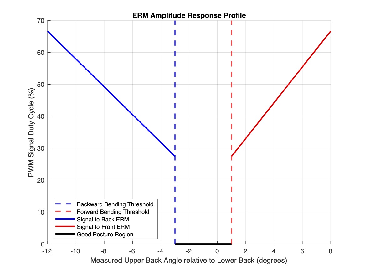
ERM Motor Response Profile vs. Measured Relative Angle Difference
Demonstration / Application
In order to determine if our device is effective in correcting posture, we conduct a study on 10 users. We ask each participant to first calibrate the vest to their posture, and then experiment with various positions to interact with the vest and assess its performance. After performing these movements, we ask the participants to rate: the quality of the feedback, the sensitivity of the device relative to their posture, and the overall comfort of the vest.
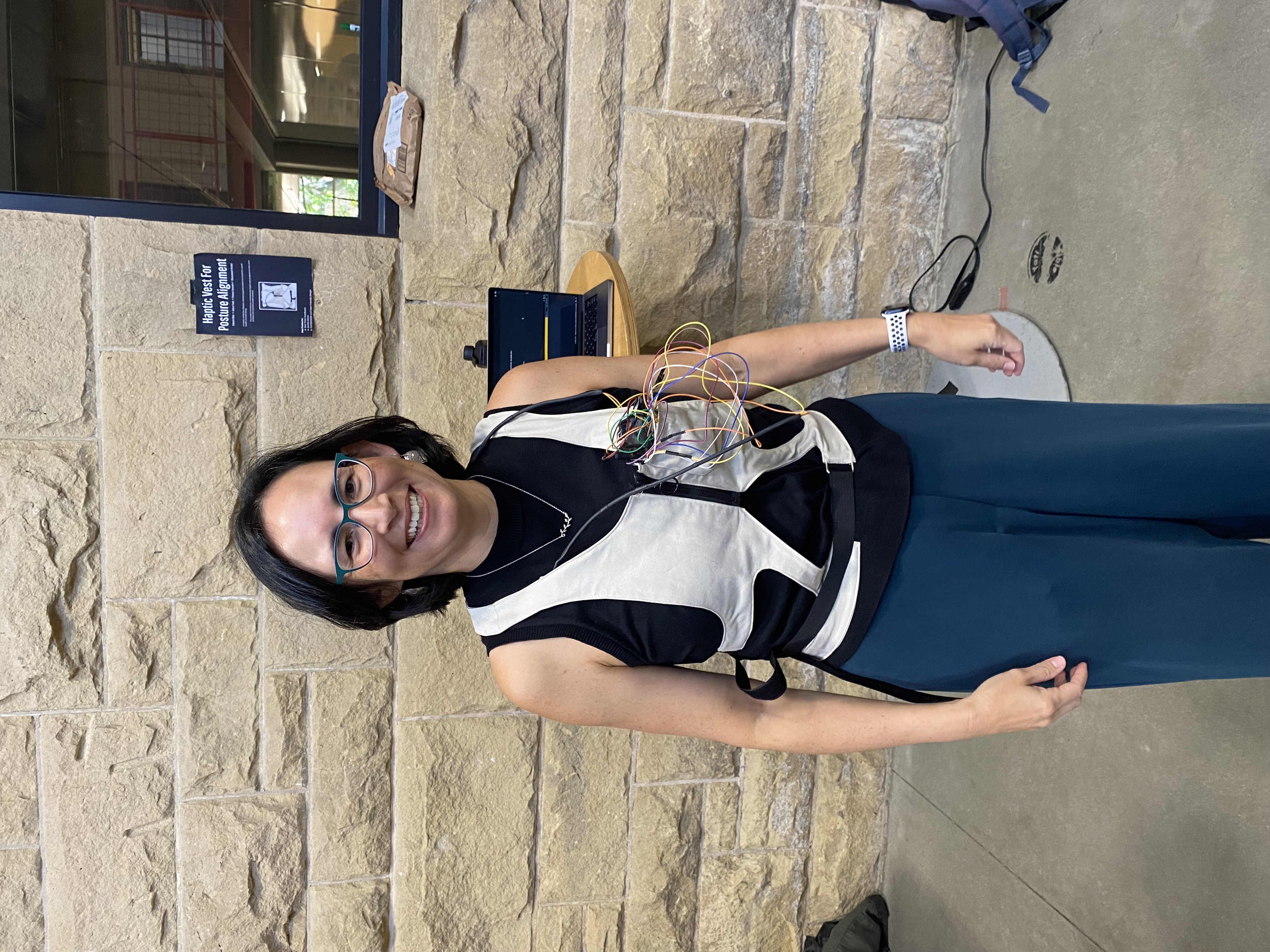
Professor Okamura Trying on the Vest
during Demo Day
Results
The following bar plot shows the results of this survey. The colored bars indicate the mean response to each question. Error bars are included to represent the standard deviation of the responses, giving a sense of the variability in the data. Additionally, individual responses are overlaid as light gray dots, providing a detailed view of the distribution of all data points. Each bar is labeled with the corresponding mean value to facilitate easy interpretation of the results.
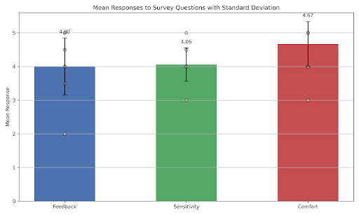
Bar Plot of Reported Haptic Vest Ratings from Demo Day
Results show that the haptic vest provides good feedback (average of 4/5), meaning that the haptic feedback is strong enough, and that users are able to correlate the haptic feedback provided with their posture. The ERMs are therefore strong enough and well positioned.
The sensitivity of the device, ie. its ability to assess the user’s posture, averages at 4.06/5. This indicates that the IMUs and the calibration phase of the vest are enough to allow for a good postural assessment, which is at the heart of the device’s control logic.
Finally, the comfort of the vest has the best user feedback with an average of 4.67/5. This is most likely due to its adjustability, which occupies a key role in the overall functionality of the vest: not only does it allow for the IMUs and ERMs to be as close to the body as possible, but it also enables for a better user experience as the device is supposed to be worn for long periods of time.
About a third of the participants mentioned that the vest was not as good at detecting bad posture when bending their back backwards, and required a large angle before providing haptic feedback. This could be improved in future iterations of this vest, with a more sensitive threshold for backwards bending.
Future Work
The vest only provides haptic feedback proportional to two different types of incorrect posture: the spinal column bending angle and the chest angle with respect to the floor. This has limits, as there are other types of incorrect postures, such as torso rotations. In future work, we would like to experiment with other types of incorrect postures to have a more accurate and complete device. Indeed, the risk of a device that does not track all incorrect postures is that it could encourage users to keep bad postural habits as no haptic feedback is provided.
Another limit of our current vest is that IMUs are susceptible to drift. This means that the vest cannot be used for long periods of time as it needs to be calibrated frequently. In future iterations of this product, we would ideally either improve our current sensor integration, calibrate more often, or use different sensors for the spinal column tracking.
Files
Github Repository:
List of Major Components:
References
[1] Lim, C. C., Basah, S. N., Ali, M. A., & Fook, C. Y. (2018). Wearable Posture Identification System for Good Sitting Position. Journal of Telecommunication, Electronic and Computer Engineering (JTEC), 10(1-16), 135–140. https://jtec.utem.edu.my/jtec/article/view/4144
[2] Ferrone A, García Patińo A, Menon C. Low Back Pain-Behavior Correction by Providing Haptic Feedbacks: A Preliminary Investigation. Sensors (Basel). 2021 Oct 28;21(21):7158. doi: 10.3390/s21217158. PMID: 34770464; PMCID: PMC8587551. https://www.ncbi.nlm.nih.gov/pmc/articles/PMC8587551/
[3] Agarwal R, Hussain A, Campolo D, Skm V. How to Train Your Posture: Haptic Feedback Can be Used for Postural Adaptation of the Trunk During Upper-Limb Motor Training. IEEE Trans Haptics. 2023 Apr-Jun;16(2):182-193. doi: 10.1109/TOH.2023.3248619. Epub 2023 Jun 20. PMID: 37027641. https://pubmed.ncbi.nlm.nih.gov/37027641/
Appendix: Project Checkpoints
Checkpoint 1
For the first checkpoint, our first goal was to get our IMU sensors and vibration motors soldered and working. We also wanted to start reading data from the IMU so we could solidify how we were going to use the live sensor data to provide haptic feedback to improve the user’s posture. One initial challenge we faced was deciding on which sensor to use for our project. Based on the existing literature we surveyed, there was a variety of sensors used for determining relative angle and position for haptics including IMUs, accelerometers, gyroscopes, etc. Given the limited time available to us for this project, we decided to go with an IMU which does not require us to integrate various sensors together to avoid drift in our measurements, and instead provides trustworthy measurements out of the box.
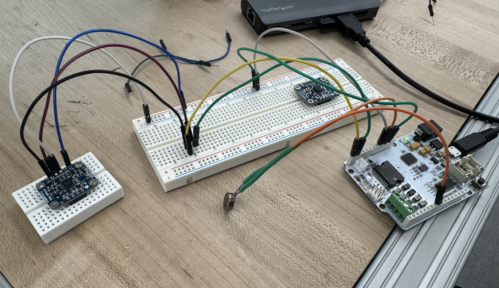
Full circuit including IMU and one vibration motor.
Another minor challenge we faced was setting up the datastream to plot live serial data from the Arduino to understand the IMU readings. We struggled trying to get Processing to visualize the live orientation of the sensor about all three of its axes. Instead, we temporarily used Arduino’s serial plotter to plot the orientation of the IMU about its axes, although we plan to primarily use the IMU’s orientation about its z-axis to determine the angle of the user’s posture. A video demonstrating this live stream of the IMU’s absolute orientation is shown below.
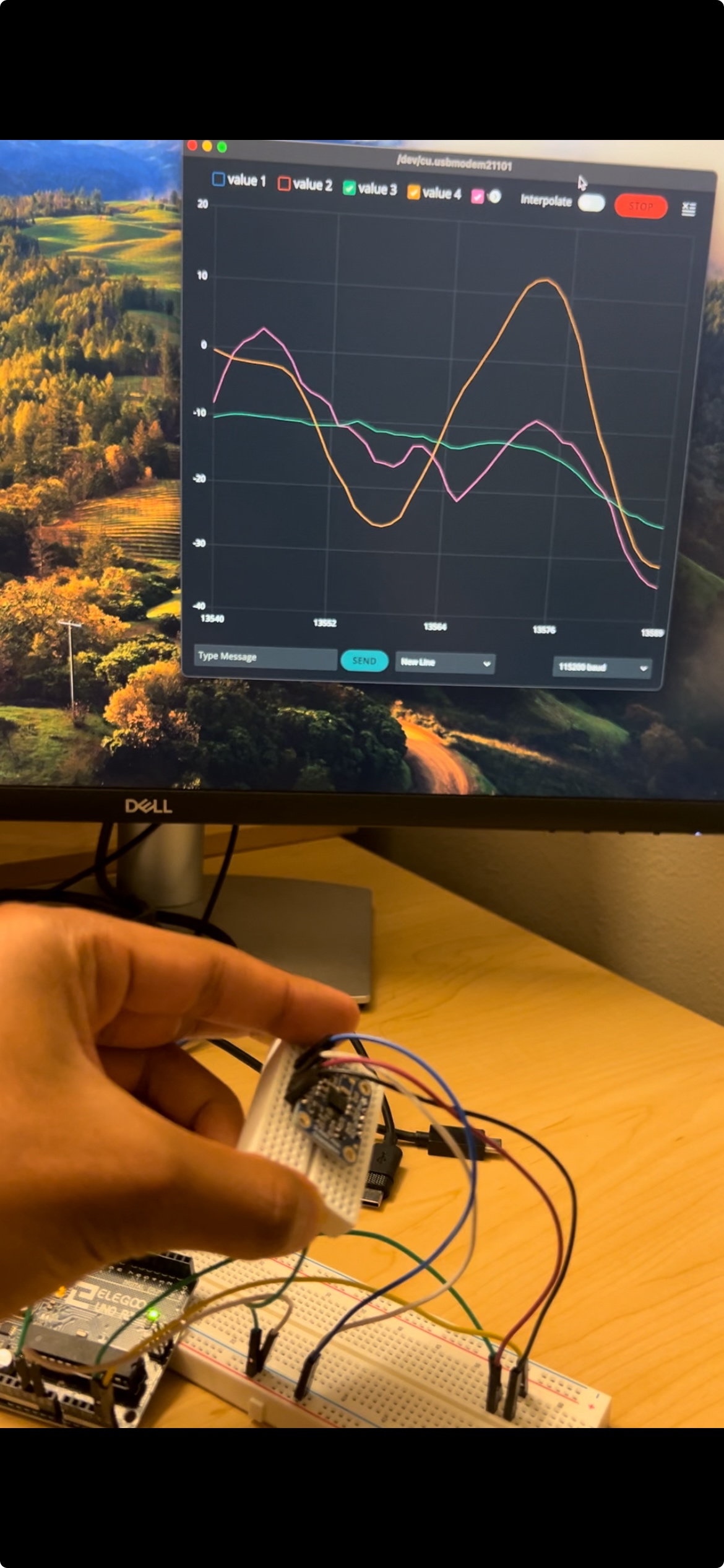
Measuring the sensor orientation about its y-axis vs. time
Overall, we met our goals of obtaining, testing, and preparing our sensors and buzzers. Our next challenge is to mount our electronics securely to one’s body to identify poor vs. good posture.
Checkpoint 2
For the second checkpoint, our goal was to finish fully integrating the system and start testing the posture correction vest on users. After completing the verification of all circuit components in the last checkpoint, since then we developed a proportional haptic feedback system that is capable of guiding the user to stay within healthy posture ranges. We wrote Arduino code that allowed the IMUs to communicate with the 2 vibration motors. We found that the system was quite responsive and that the proportional feedback control was an intuitive way to guide the user away from bad postures.
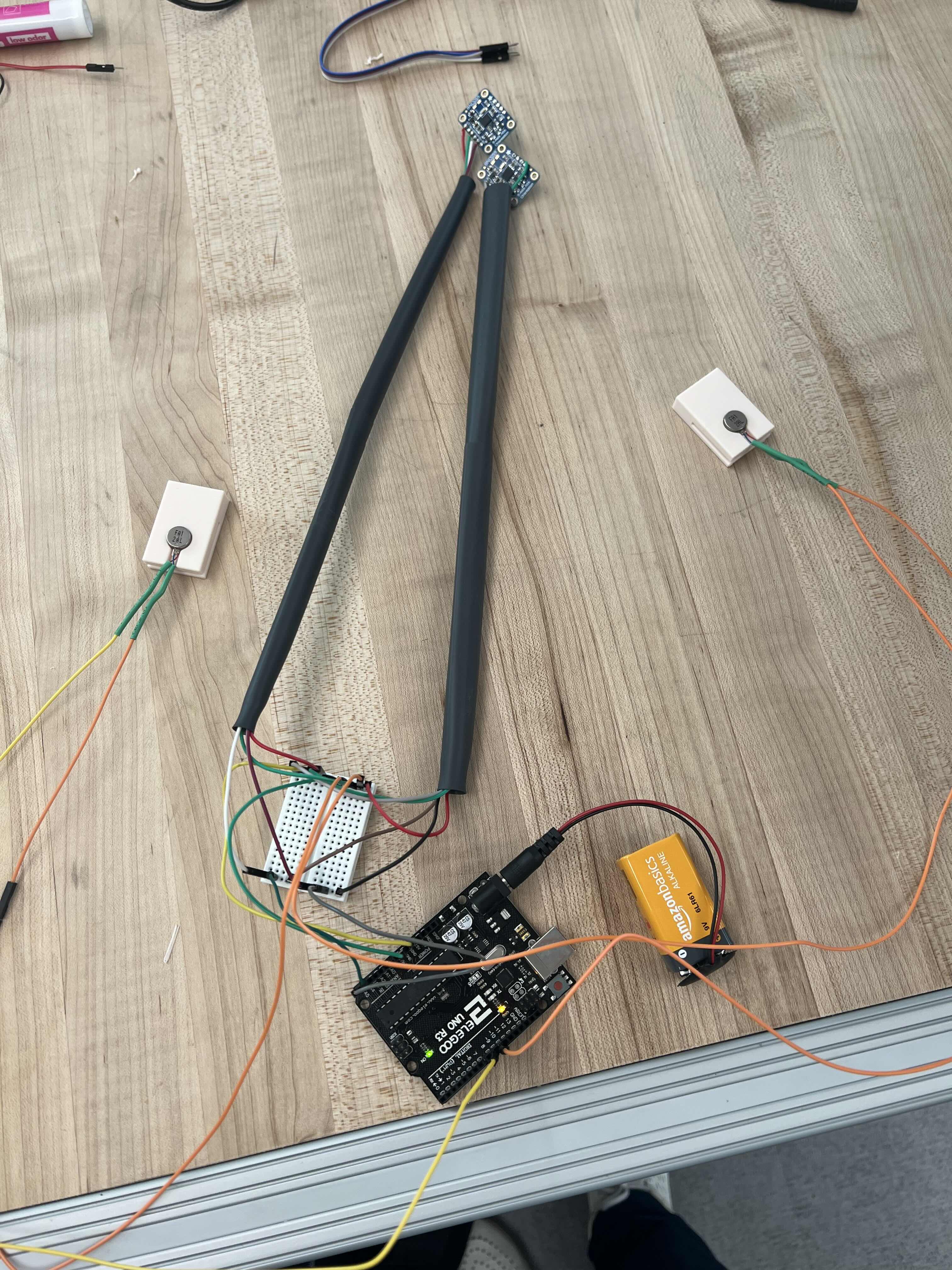
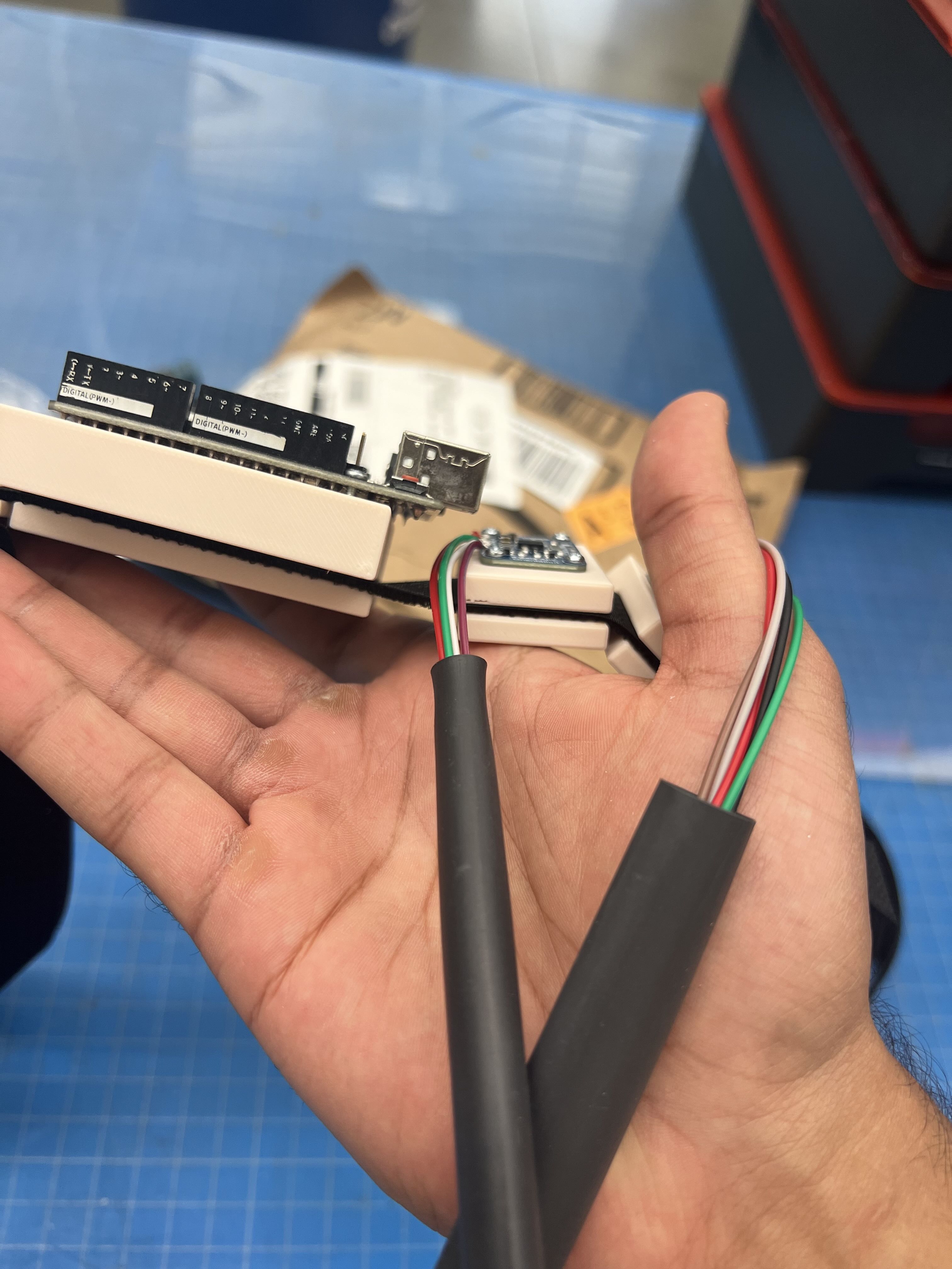
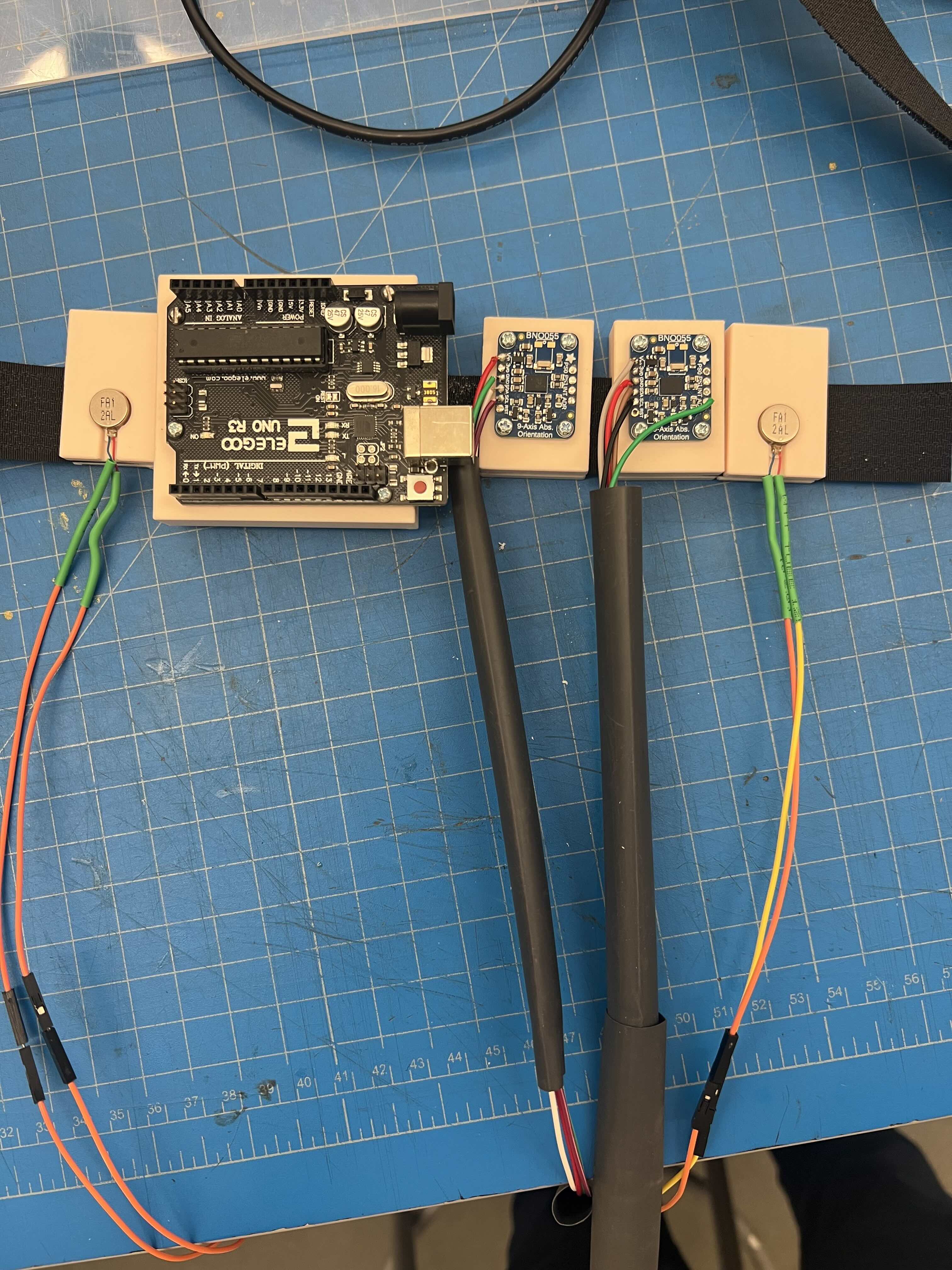
Electronic System Integrated Together
Testing the Haptic Feedback while Changing the Relative Orientation between the IMUs
Additionally, we made a lot of progress on fabricating the physical vest set up that would host all of the electronics on board. We decided that we would use a combination of sown materials and velcro straps to design a vest that could easily attach to the user while providing a snug fit to ensure the vibration feedback was clear. The first step in this process was moving from the breadboard to a protoboard, at the same time improving the wiring of our system and cleaning it up with additional insulation and heat-gunning. Next, we dedicated a lot of time to 3D-Printing custom clips for different electrical components to allow easy attachment to the velcro straps. We also spent time sewing fabric for a vest that would attach to the velcro straps and hold some of our circuit components.
3D-Printed Clips for Mounting and Attaching Electronics to Velcro Straps
The most challenging piece for this week was the vest fabrication. Designing a vest that fit well and had a snug enough fit to provide clear and direct vibration feedback required to us to iterate on printed parts and fabric designs. Looking forward, our next biggest challenge/concern at this point is how we want to approach our dynamics analysis for the final report. Because our vibration system is relatively simple and does not provide any meaningful force feedback we will have to think of what dynamics analysis is meaningful to perform here.