

2024-Group 8

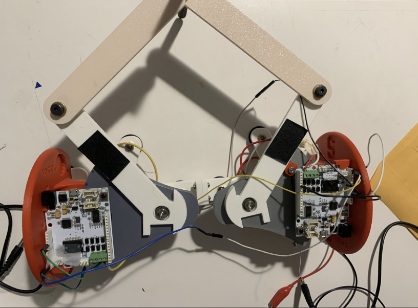
2-DoF pantograph with scalpel and
correlated graphics.
2 DOF Haptic Simulation for Robot Assistive Upper Limb Surgery
Project team member(s): Zarrin Bashir, Richard Lee, Sean Sewell, Akansha Singh

This project aims to simulate upper limb surgery via a haptic force feedback apparatus, as a device to aid surgeons-in-training. The device takes in user input via a 3D printed stylus mimicked as a cursor on a virtual diagram of the upper limb mapped using the software Processing. The user is instructed to move through the environment given the constraints of the 2-DoF haptic device and asked to detect how that movement is mimicked visually and haptically. The apparatus works to establish a multitude of different forces located within the environment set up by the Hapkit placed in a designed pantograph structure. We constructed regions of variable stiffness attributed to free movement, the viscoelastic properties of muscle, and lastly bone, where users were constrained from piercing. Simulation of incision of muscle tissue was calculated based on literature, which informed our simulations and embedded force feedback on the surgical device. Overall, this device takes advantage of Standard Linear Solid (SLS) models to replicate viscoelastic material dynamics on the leader and follower Hapkits, coupled via the manufactured pantograph, which informed comparison of the device to our idealized simulation of muscle behavior. Correlations between these results prove the efficacy of the apparatus with intended future work on simulating other parts of the body, implementing optimized smoothness, and eventually, teleoperation.
On this page... (hide)
Introduction
When training for surgery, residents and medical students must learn and adapt to different kinds of techniques required in different components of the human body. Especially when conducting surgery, doctors must be vigilant to not penetrate or cut into critical tissue or tissue that is to remain untouched.
Hence, the motivation of this project is to provide itself as a training tool for medical students and residents. The focus of the surgery is in the application of the shoulder ball and joint and its surrounding tissue. Given a certain level of simplification, this 2 DOF pantograph haptic device allows for the user to move their “scalpel” in free space in time. In conjunction, a visual graphic is displayed showcasing the user’s position as the user interacts in the virtual world. The user may meet appropriate force feedback when necessary when their position is hitting areas of the shoulder that are not to be touched, for example the bone.
Background
In the modern age, there has been a drive and push for advanced medical devices including stepping deeper into minimally invasive surgery. However a downfall of stepping towards minimally invasive surgery often leaves the surgeons with minimal touch feedback when conducting surgery [Basdogan]. This results in greater operation training, sometimes as high as 750 operations [Castillejos], to be fluent and to identify and work with total net force resulting from the tissue interactions [Basdogan].
Current existing haptic devices in this field fall under one of the following: impedance control and admittance control [Castillejos]. The former works by allowing the user to initiate a motion followed with feedback done by a computer, a generally more simplistic device commonly seen. The latter works by allowing the user to make a motion followed by feedback done by the device, a type of device not commonly used in training applications due to its larger nature and build [Castillejos].
One example of a haptic device in surgical training includes palpation, a technique done by surgeons in which they use their fingers against tissue to gauge its stiffness. A haptic device constructed via Microsoft Kinect constructs a finite element model (FEM) of soft tissue to allow for modification of geometry [Castillejos].
Another example of a haptic device in surgical training that aligns a little closer to this project includes computer simulation of knee and shoulder arthroscopy [Modi]. Simulations for this surgery including force feedback with computer generated data demonstrate consistency. Moreover, these simulations have allowed for greater skill refinement in the context of this surgery, particularly for individuals not well educated on medical techniques [Modi]. However, this field of haptics is still new at large and its efficacy and applications into surgical training have yet to be more thoroughly explored.
Methods
Hardware Design and Implementation
Our hardware apparatus is a 3D printed 2 DOF pantograph incorporating two Hapkits. We used the Graphkit design from the Hapkit website. The handle, or "tool" of our device was designed to resemble a surgical scalpel. We wanted to have a design that allowed a range of flexible motion and would simulate the feel of doing a surgery. The linkages and revolute joints of the pantograph design enabled that feel.
After initial assembly, we did feel the device had a limited workspace, however after implementing both the Arduino and Processing codes, we realized it would be compensated. We felt that the device had enough workspace for the upper limb surgery application of our project, which does not require wide and erratic movements on the physical device.
...
System Analysis and Control
The general approach for modeling the system dynamics and analysis of this system stem from the Standard Viscoelastic Solid Model. This model was used to represent the characteristics of the muscle tissue, specifically in the context of modeling muscle tissue behavior during surgery. The end goal was to be able to model the viscoelasticity of muscle tissue over a period of time in the context of surgery.

Shown above is a representation of the Standard Viscoelastic Solid used for modeling the ideal muscle dynamics pulled from online resources [Humphrey]. The model utilizes a spring in parallel to the Maxwell Element Model [Humphrey]. From this set up, equations for force during stress relaxation and creep can be derived shown below.

Figure 1: Force (N) vs Time (s) for Ideal Dynamic Simulation

Figure 2: Force (N) vs Time (s) for Arduino this force was obtained by entering the muscle at a high velocity, then stopping 0.007 m - 0.01 m into the muscle to observe constant strain decay. Muscle length ~ 0.03 m.
Force
The Force vs Time graph shown above decreases until it reaches a constant value close to zero which can be represented in our system. As the scalpel is making an incision into the muscle, there is a force that is induced from the tension of the scalpel pushing into the muscle. At the beginning of the incision, the force is high. However, the moment the scalpel breaks the barrier of the muscle and is able to cut through, there is no longer any force being induced into the muscle as the scalpel is located within the environment of the muscle hence as an approximated zero value for force.
The equation [Humphrey] used for this modeling are derived from the following:

where the stress is plotted as a function of time with values including Young’s Modulus, initial strain, and shear modulus extrapolated from research papers. In order to get force, the stress was multiplied against the area of the upper edge of the deltoid muscle, also pulled from online papers.
When comparing the Arduino force data to the simulated ideal data, the overall trend is relatively similar. The force experiences an exponential decay over time. There is presence of noise in the Arduino data but given the constraints of the project and limitations of resources, the general objective of modeling muscle tissue in surgery was achieved.
For an in depth explanation of the code implementation into Arduino, refer to Software Design.
Creep

Figure 3: Creep depicted as Strain vs Time for muscle relaxation.
The Creep vs Time graph shown above increases until it reaches a constant value which can be represented in our system. As the scalpel is making an incision into the muscle, there is a change in length, and therefore a strain, that is induced. At the beginning of the incision, the change in length is minimal hence a lower strain. As the scalpel makes greater movement into the muscle, there is greater strain observed as seen in the increasing graph above. However, the moment the scalpel breaks the barrier of the muscle and is able to cut through, there is not longer any strain being induced into the muscle as the scalpel is located within the environment of the muscle hence depicted as a constant strain value.
The equations [Humphrey] used for this modeling are derived from the following:

where the strain is plotted as a function of time with values including Young’s Modulus, initial strain, and shear modulus extrapolated from research papers.
For our device, we used two Hapkit boards as our microcontrollers (similar to Arduino Uno), and Processing, a coding platform used for graphics. Our boards were used to convey haptic feedback to the user through our device whilst they are performing the simulated surgical “incision”. Each board tracked the location of the device handle, or the “scalpel,” and as the user moved the tool, the dynamic feeling of making an incision through muscle (viscoelastic material) and reaching the bone (similar to wall) is rendered.
...
Software Design
For graphics and communication, we used Processing to convey the force feedback to the user visually. In our Processing output screen, we have an image of a Shoulder Ball-Joint diagram, and a "cursor" that communicates between the Arduino code, the background image, and the physical haptic device.
Forward Kinematics: As detailed in checkpoint 1, we used the pantograph equations detailed by Campion [Campion]. We connected the leader and follower hapkits via I2C. The leader Hapkit calculated its own handle angle (theta1), then requested theta5 from the follower Hapkit in order to calculate the position of the end-effector.
Force Feedback:

Figure 4: Schematic of muscle regions for simulation
Bone Rendering
The shoulder and arm bone were rendered as a lollipop shape with high stiffness.
This shoulder joint was rendered as a circle. From the position of the end-effector, we calculated the vector directed radially outward to the nearest point on the circle. We then split this vector into x and y components, and used these equations as displacements in the Fx and Fy directions to render a spring force. The arm bones were simply rendered as walls that began slightly below the centerline of the circle, with displacement being calculated only in the x direction.

Muscle Rendering
The muscle was modeled as a square region encapsulating the bone that provided feedback opposing motion toward the bone (in order to simulate the feeling of cutting). This force was calculated with the Kelvin-Voight model, which is a common model used to describe the behavior of soft tissues. It is an adapted spring-damper system that calculates the stress in a material based on strain and strain rate.

Figure 5: Free body diagram of force of muscle
Representative values for the spring rate and damping coefficient were found from literature values (E and mu discussed in the System Analysis section). To calculate the strain, we took the displacement between the current x position and the edge of the muscle region. We then divided this by the overall length of the muscle, which was the edge of the muscle region to the center of the bone. To calculate strain rate, we saved the previous strain value, and took the difference divided by an estimated dt. We also smoothed this rate. From strain and strain rate, we were able to calculate a stress value. We then scaled this by an area to give us force on the scalpel.
We wanted to mimic the stress relaxation that one would feel actually stretching and cutting through tissue. This feeling is achieved via the damper in the system, as once the user stops moving, the force will sharply drop to only the spring force. However, in a scenario where one was actually cutting through tissue, there would be an eventual failure where the force feedback should drop all the way to zero. So we wanted to make sure that even after the initial drop in force, the applied force eventually decreases to near-zero no-matter how much the spring is stretched. We achieved this by adding an exponential decay to our stress value. If the strain rate was sufficiently low (meaning the user was no longer moving the cursor), the exponential function is applied to the stress to make sure that the force decays to zero. When the user moves again, meaning they are cutting through new tissue, the exponential function is no longer applied.

With this spring damper system and decay function, we were hoping to get as close as possible to the Standard Linear Solid Model, which is the most realistic model to describe the behavior of soft tissue. Above in the analysis section we compare our force feedback at constant strain to the force that should come from the SLS model at constant strain.
For graphics and communication, we used Processing to convey the force feedback to the user visually. In our Processing output screen, we have an image of a Shoulder Ball-Joint diagram, and a "cursor" that communicates between the Arduino code, the background image, and the physical haptic device.
Software Challenges
One of the biggest challenges when it came to communicating with the graphics, was programming the shape of the ball joint and having it simultaneously match the tracing of the shoulder joint in the background image and have it convey realistic force feedback to the user.
Bone Rendering It was difficult to render the shoulder in a ball shape, and although we came up with s solution, the points where the ball meets the bone wall produced jittering in the force feedback that we were not able to account for.
We initially attempted to directly use the SLS model in our code by implementing the following equation for stress.

Although the differential value for strain was easy to calculate, in order to calculate the time differential of stress, we had to save both the previous, and the previous previous stress value. (This was because strain could be calculated without differentials, whereas stress could not). This strategy lead to the stress value blowing up after only a few iterations. After this equation with two differentials proved too difficult, we switched to the Kelvin-Voigt Model detailed earlier, which only requires the strain rate.
Another challenge with rendering the muscle was ensuring that the force only rendered outward. We initially intended for the muscle to be rendered as a larger lollipop surrounding the bone lollipop. Rendering the circular part of the muscle lollipop required calculating the strain rate in both the x and y directions, then ensuring that the force pointed only radially out of the circle. Rendering the Kelvin-Voight force in both x and y directions caused jitters in the force feedback that were unpleasant, and ensuring that the force was only applied in one direction was difficult due to the changing sign of the strain rate. So after much trial and error we decided to only provide damping feedback in the x-direction as shown above.
Demonstration / Application
The processing code was used during the demonstration of the apparatus. The code is structured such that the shoulder anatomy joint image is imported with the starting cursor position being located at the center of the image. The Arduino publishes x and y positions of the Arduino and converts them to pixel coordinates. The points are then mapped onto the image allowing the user to see their location as a moving cursor during the apparatus’s usage.
The apparatus was showcased at the ME327 Open House on June 4th. The device performed as anticipated with no issues or bugs arising during its performance. The user’s responses were recorded noting their evaluation of force feedback, motion smoothness, and overall usage of the apparatus. The demonstration was fascinating for users as they explored the different implications and applications of surgical simulation via haptics.
Results
During the open house showcase of our project, 18 users reported feedback as to their experience using the device. Our primary focus of receiving feedback was to understand the comprehensibility of the different mappings and systems that we modeled within the surgical simulation. As such, four questions were asked, for which the following figures indicate with the form question as its title and respective scales:

Graph 1: In the first aspect of user testing, we had participants indicate if they felt a bone structure similar to the shape and form indicated in the processing graphic. It was observed that on a scale from 1 (not noticeable) to 10 (noticeable), the average rating was a 9.5 for noticeability (standard deviation of 0.79), which indicated that the 18 participants generally were able to identify the bone and felt that it was noticeable as a haptic sensation on the Hapkit.

Graph 2: Based on this second figure, the viscoelastic properties appeared to have more variable results with regards to how noticeable they were. Across all 18 participants there was an average reported score of 6.55 for the noticeability, with a standard deviation of 3.11. The high standard deviation indicates that some participants did not find the dynamically modeled damping factors as noticeable while others found them very noticeable (with 8 responses of >8 on the noticeability scale). This range of responses may be due to varying degrees of familiarity with the damping factors at play (which informs perceptual bias) and varying velocities for which each of the participants was engaging with the surgery.

Graph 3: Next, participants were asked how stable they felt the movement of the pantograph was when using the scalpel. The stability was rated with an average of 8.89 and standard deviation of 1.41. This meant that in general, our physical prototype for the 2-DoF device was considered to be stable in its movement.

Graph 4: Regarding the graphics that were implemented, there was an average reported score of 9.5 with a standard deviation of 0.79 for the motion accuracy on Processing. This indicates that overall, users agreed that the graphics were closely related to the haptic phenomena, and verifies the effectiveness of our pantograph-graphics mapping in a visual representation.
Holistically, the results of our user testing indicates that the surgical device and its corresponding aspects of feedback were largely considered noticeable and stable. With regards to the greater variance in the noticeability of the incision dynamics rendering, it is important to note that this is intended to be a surgeon training device, therefore creating a more noticeable gradient for which the haptic feedback could be rendered would be an effective next step in improving our system and users' experience. The results indicate that our system was effective in mapping components of surgery to a virtual, visual and haptic simulation device.
Future Work
The surgical simulation haptic device could be tested under the guise of an individual with little to no medical training. Ideally after a few training sessions, said individual would be able to trace the shoulder and learn to identify how, when, and where to avoid the collision created by the force feedback within the haptic device. Moreover, testing how the system and how it may relate to varying shoulder sizes could have important implications. Essentially, understanding, quantifying, and documenting the ways in which the shoulder of a 6’3’’ individual vs that of a 5’2’’ individual varies when using this haptic device is imperative. The generalizability of the device with varying anatomy (shapes, sizes, weights, genders, etc) would be a good test to its ramifications in the context of surgery.
Another test, and potential future step, could be to implement this concept and make it customizable to varying parts of the human body. At current, the device works only in the capacity of the shoulder but expanding to the femur bone, rib cage, or ankle joint could allow for greater flexibility and hence its usage.
Some ways the haptic device can be improved is to implement different levels of force feedback. At current, the model simplifies both human anatomy of the shoulder and its surgery to a 2D model with movement present in the xy direction but not depth, aka within the z direction. Moreover, taking into account the varying levels of force feedback present within the muscle vs the bone vs something as simple as arteries and veins would add to the complexity of the project and bring it one step closer to emulating actual surgery.
Another component to build upon the system would be to implement a larger range of motion for the pantograph. By nature and construction of the device, the pantograph has a very limited range of motion, depicted as almost a rhombus. Expanding the range of motion of this into a larger semicircle would be ideal and better for reaching further distanced areas.
Lastly, constructing an organized way in which the initial position of the pantograph can be declared would be incredibly beneficial for calibration. This would allow for more customization with where an individual may want the device’s free range of motion to exist within the context of the surgery.
How this device can be applied would be under the guise of surgical training for the shoulder in specific. By incorporating force feedback into the device for surgery at the shoulder, an individual, given enough training, should be able to develop an inherent sense into which areas of the shoulder to push their scalpel in surgery and in which areas to not.
Acknowledgments
Our team would like to thank the ME327 Teaching Staff for their expertise in helping this project come to fruition. We would like to extend our gratitude to Dani Algazi for helping with project scoping as well as Prof. Okamura and the Hapkit team for the GraphKit models. We would also like to thank the Product Realization Lab, Max Lab, and Room 36 staff for providing resources for our component fabrication.
Files
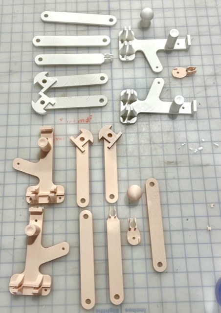
Manufacturing of our device was based on the schematics provided by the Hapkit team from Stanford University. These files may be retrieved from 2-DoF Devices (Graphkit) to be 3D printed. Additional fasteners for the two links were purchased from the Product Realization Lab, totaling to $11.60 for those components and the full fabrication.
Leader code for pantograph (Arduino): Attach:2024t8_leader.zip
Follower code for pantograph (Arduino): Attach:2024t8_follower.zip
Processing code with upper limb diagram: Attach:ShoulderJoint.zip
MATLAB script for simulating viscoelasticity dynamics + serial data: Attach:2024t8_analysis.zip
References
Basdogan, C., De, S., Kim, J., Muniyandi, M., Kim, H., & Srinivasan, M. A. (2004, April). Haptics in minimally invasive surgical simulation and training. IEEE Computer Graphics and Applications. https://ieeexplore.ieee.org/abstract/document/1274062/authors#authors
Bouaicha, Samy & Slankamenac, Ksenija & Moor, Beat & Tok, Sina & Andreisek, Gustav & Finkenstädt, Tim. (2016). Cross-Sectional Area of the Rotator Cuff Muscles in MRI - Is there Evidence for a Biomechanical Balanced Shoulder?. PloS one. 11. e0157946. 10.1371/journal.pone.0157946.
Campion, G., Wang, Qi, and Hayward, V. (2005). The Pantograph Mk-II: a haptic instrument. 2005 IEEE/RSJ International Conference on Intelligent Robots and Systems. https://ieeexplore.ieee.org/document/1545066
Escobar-Castillejos, D., Noguez, J., Neri, L., Magana, A., & Benes, B. (2016). A Review of Simulators with Haptic Devices for Medical Training. Journal of Medical Systems, 40(4). https://doi.org/10.1007/s10916-016-0459-8
“Hapkit.” Hapkit.stanford.edu, hapkit.stanford.edu/twoDOF.html. Accessed 1 June 2024.
Hatta, Taku et al. “Quantified Mechanical Properties of the Deltoid Muscle Using the Shear Wave Elastography: Potential Implications for Reverse Shoulder Arthroplasty.” PloS one vol. 11,5 e0155102. 6 May. 2016, doi:10.1371/journal.pone.0155102
Humphrey, J. D., & Delange, S. L. (2004). An introduction to biomechanics : solids and fluids, analysis and design. Springer.
Isogai, Kaoru et al. “Young's moduli of subcutaneous tissues and muscles under different loads at the gluteal region calculated using ultrasonography.” Journal of physical therapy science vol. 34,12 (2022): 777-783. doi:10.1589/jpts.34.777
Modi, Chetan S., et al. “Computer-Simulation Training for Knee and Shoulder Arthroscopic Surgery.” Arthroscopy: The Journal of Arthroscopic & Related Surgery, vol. 26, no. 6, June 2010, pp. 832–40, https://doi.org/10.1016/j.arthro.2009.12.033. Accessed 29 Feb. 2020.
Shoulder Anatomy. Matthew Provencher MD, MBA, CAPT MC USNR (Ret.), https://matthewprovenchermd.com/shoulder-anatomy-joint-pain-vail-aspen-denver-co/. “Standard Linear Solid Model.” Wikipedia, 27 Feb. 2020, en.wikipedia.org/wiki/Standard_linear_solid_model.
Yu, Menglei et al. “Young's Modulus of Bilateral Infraspinatus Tendon Measured in Different Postures by Shear Wave Elastography Before and After Exercise.” Orthopaedic surgery vol. 13,5 (2021): 1570-1578. doi:10.1111/os.12989
Zhang, L Q et al. “Stiffness, viscosity, and upper-limb inertia about the glenohumeral abduction axis.” Journal of orthopaedic research : official publication of the Orthopaedic Research Society vol. 18,1 (2000): 94-100. doi:10.1002/jor.1100180114
Appendix: Project Checkpoints
Checkpoint 1
We plan to design a 2 DOF haptic device, and have a simulated apparatus (most likely graphics) for the environment the device will be used in. The environment in our case would be like a simulated surgical theater, similar to the popular game of Operation.
What has been done so far: (1) 3D printed parts for original design (2) Looked into the Kinematics/Dynamics for our design & wrote Pseudocode for Leader Arduino
Our team is planning to build upon the "Graphkit" provided in the Hapkit website. We have printed out the 3D parts for the Graphkit, which consists of a pantograph design, and we are prepared to assemble before Checkpoint 2.
To find the Kinematics and Dynamics of the device, we referenced this paper: https://ieeexplore.ieee.org/document/1545066 by Campion, Wang, and Howard.


This is the same paper that previous ME327 groups have referenced to find the pantograph dynamics. In the Pseudocode, you can see that we find the position of joint 2 and 4 using the same method we used for our Hapkit assignments. With these vectors and angles, we can then calculate the position of the end-effector. We will then calculate the force based on this position. We will likely have obstacles, or the outlines of a human body in our graphics. How much force we apply, and in which direction, will depend on on the position of the end-effector and how far it has entered an obstacle. The most difficult part of this is determining how to distribute the torques to each motor. It seems like we could do this based on the Jacobian (also calculated in the pseudocode from equations in the paper). For future work we want to determine how to best adapt this to our situation, and also investigate whether we could just distribute the torques based on position alone. Attach:LeaderPsuedo2.txt
Our group plans to accomplish our minimal goal before our 2nd checkpoint. Which mainly consists of (1) assembling our 1 pantograph (2 Hapkits) with a corresponding virtual environment. (2) Coding Haptic feedback provided based on virtual obstacles.
Checkpoint 2
We decided to go forward with our minimal goal (or version 1 of our project), which consisted of having 1 pantograph and a virtual environment. The virtual environment that we decided upon is a simulated surgery of a shoulder joint.
What has been done so far: (1) Assembled device. 1 pantograph with 2 Hapkits. (2) Set up preliminary virtual environment using Processing. (3) Leader and Follower code on Arduino for the two Hapkits to communicate with each other and Processing. Applied Kinematics. (4) Code for the force feedback of the shoulder ball-joint structure. (Rendering) (5) Started off Dynamic analysis
1. Assembled device. From the 3D printed parts that we had done for the previous checkpoint, we assembled 1 4-linked pantograph with 2 of our Hapkits. We assembled it using instructions for the Graphkit provided in the Hapkit’s site.

2. Virtual environment. The focus of the project is to work to simulate what shoulder joint surgery would be like and the kind of force feedback one would get in response to that. This could be as a result of an injury to the ball and socket joint, bone damage, or muscle tissue damage in that area.
The arduino code works to establish a cursor for the user aka where the user is located with respect to the virtual environment. The processing code follows the user’s position depicted as an ellipse that will in theory react to different dynamic walls present in the system that work to emulate what would be tissue in the human body.

The code we have so far for our ellipse "cursor."


3. Leader and follower pantograph code. Our pantograph is structured in a Leader-follower format where the leader receives an angle (calculated from the mr sensor reading) from the follower in order to calculate the position of the end-effector. The leader will also need to send a torque value to the follower when we determine the necessary force-feedback based on the position. At first we planned to use Serial communication to send these values back and forth. However, because we also plan to use graphics with Processing, using serial communication might have interfered with our graphics. Instead, we decided to use I2C communication, which had been used by previous ME327 groups to communicate between Arduinos. In order to use I2C, we connected the SDA and SCL ports on the hapkits. We then designated the Leader as the controller, and the Follower as the peripheral. When the leader needs the follower’s angle, it sends a request via I2C to the follower. The follower has an “request received” event handler, which will translate the angle into an array of ASCII characters, and sends these to the Leader.


For this 2nd checkpoint, we also fleshed out the forward kinematics pseudocode for the position estimation of the end-effector.

4. Code for rendering shoulder ball-joint. For simulation of a ball joint of a shoulder, we parametrized curves and pseudocode for where the positions of the spherical joint of the upper limb as well as bones would be. These would be rendered as still walls where the incision tool would be unable to cut through. In terms of next steps, our team is aiming to map these curves and walls to their respective locations on both our graphics and the constructed pantograph. Based on the scope of the reach of the pantograph, we will then place the “joints” in appropriate spaces.

5. Dynamic analysis progress. Regarding dynamic analysis, our rendering of friction would be modeled based on the dynamical systems for stiffness and viscosity found by orthopedic researchers. From Zhang et al. (2000), the stiffnesses and viscosities of the glenohumeral abduction axis were studied using a spring damper model and second-order differential equations. The following equations from their study will be used to model the viscosity and therefore posit a dampened torque when conducting the robotic surgery. This notably correlates damping ratios, natural undamped frequencies, and static gains of elements that are linearly related.
