

2025-Group 10
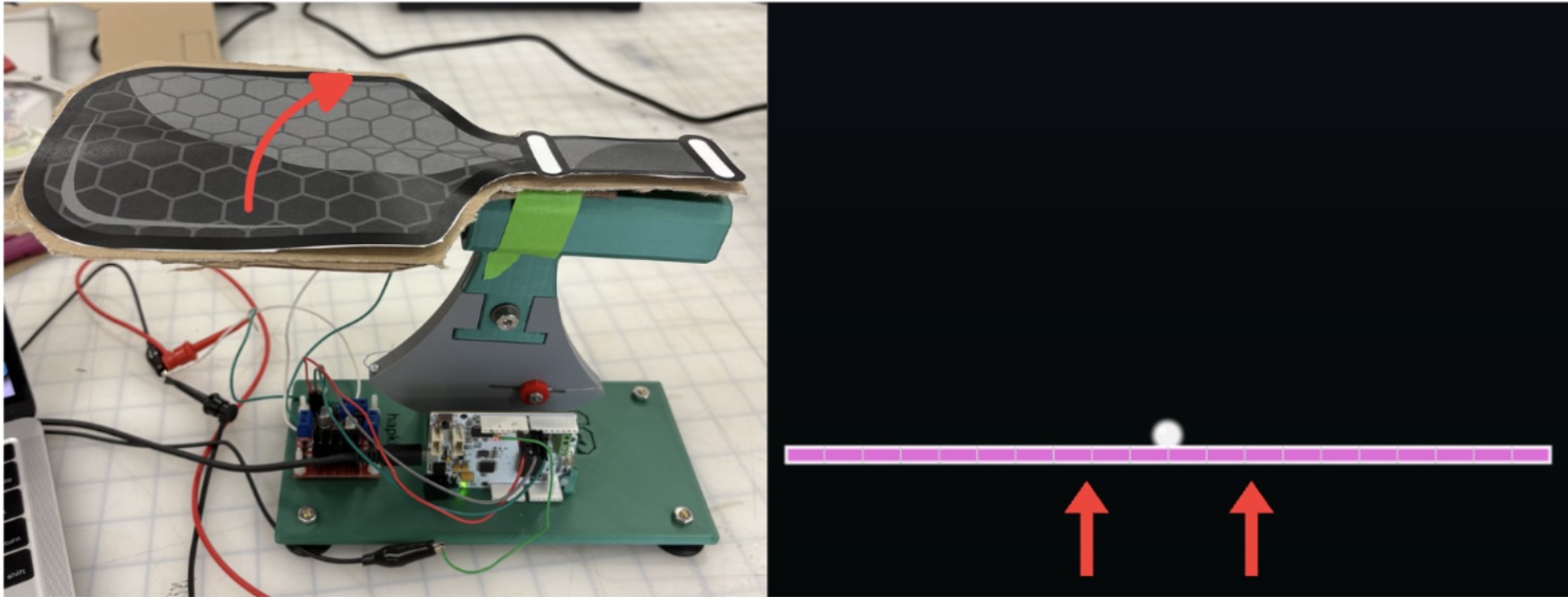
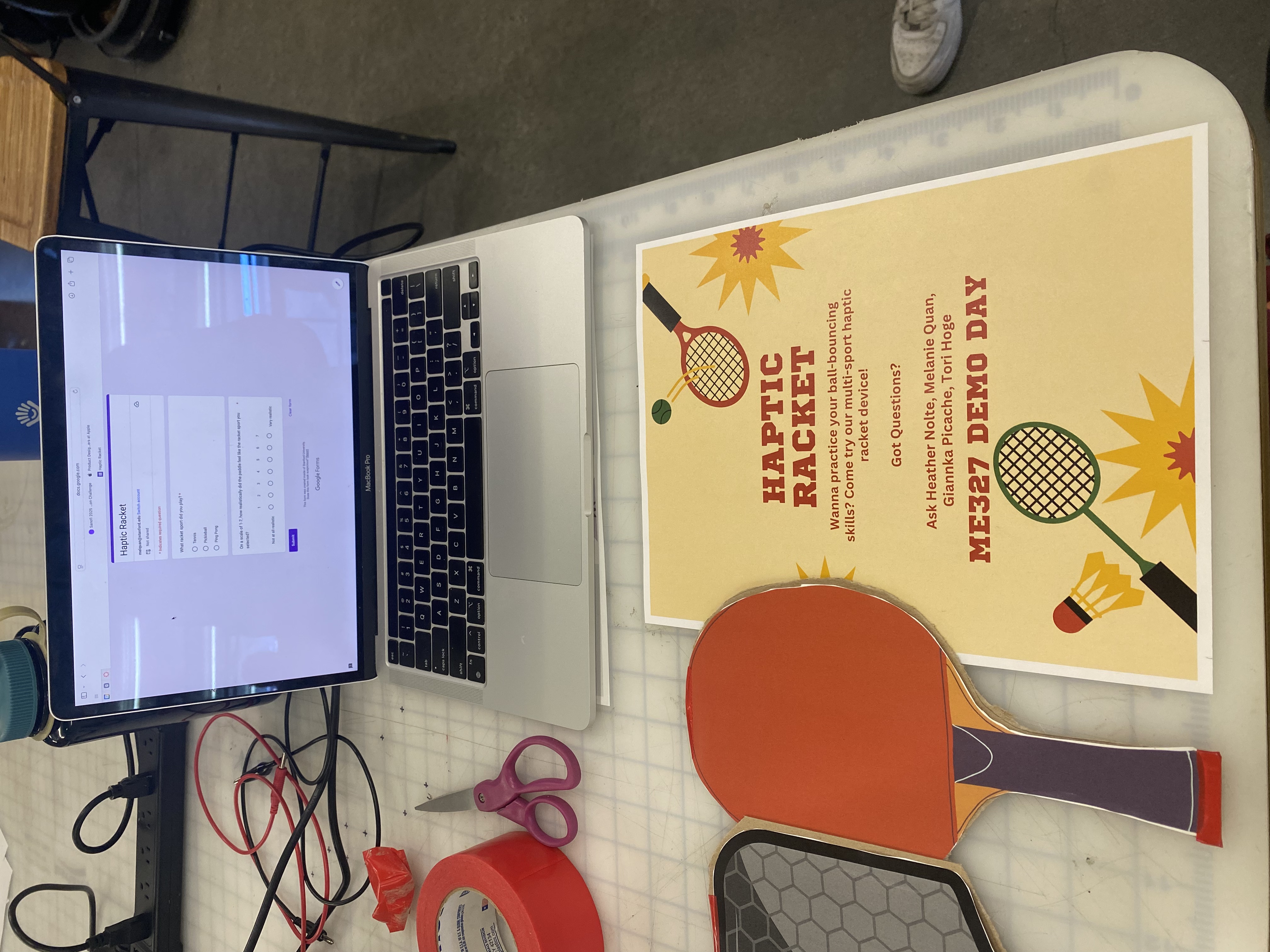
The Haptic Racket setup at the open house
Haptic Racket
Project team member(s): Tori Hoge, Giannka Picache, Melanie Quan, & Heather Nolte
This project introduces an interactive game centered around racket sports, allowing users to engage in ping pong, tennis, and pickleball using a single multifunctional racket handle. Players can switch between different sports, providing a unique opportunity to explore and compare the nuances and distinct gameplay mechanics of each sport. The game not only delivers an immersive experience but also incorporates precise haptic feedback tailored to each sport, enhancing the realism of gameplay. Participants engage with the game on a screen, where they can strike the ball repeatedly, with a built-in bounce counter that adds a competitive element to their sessions. Testing at the ME327 Haptic Open House received enthusiastic responses from users, who commented on the game's realism and overall engagement. The positive feedback highlighted the effectiveness of the haptic feedback in replicating the feel of real-life racket sports, making it a promising addition to the realm of interactive gaming.
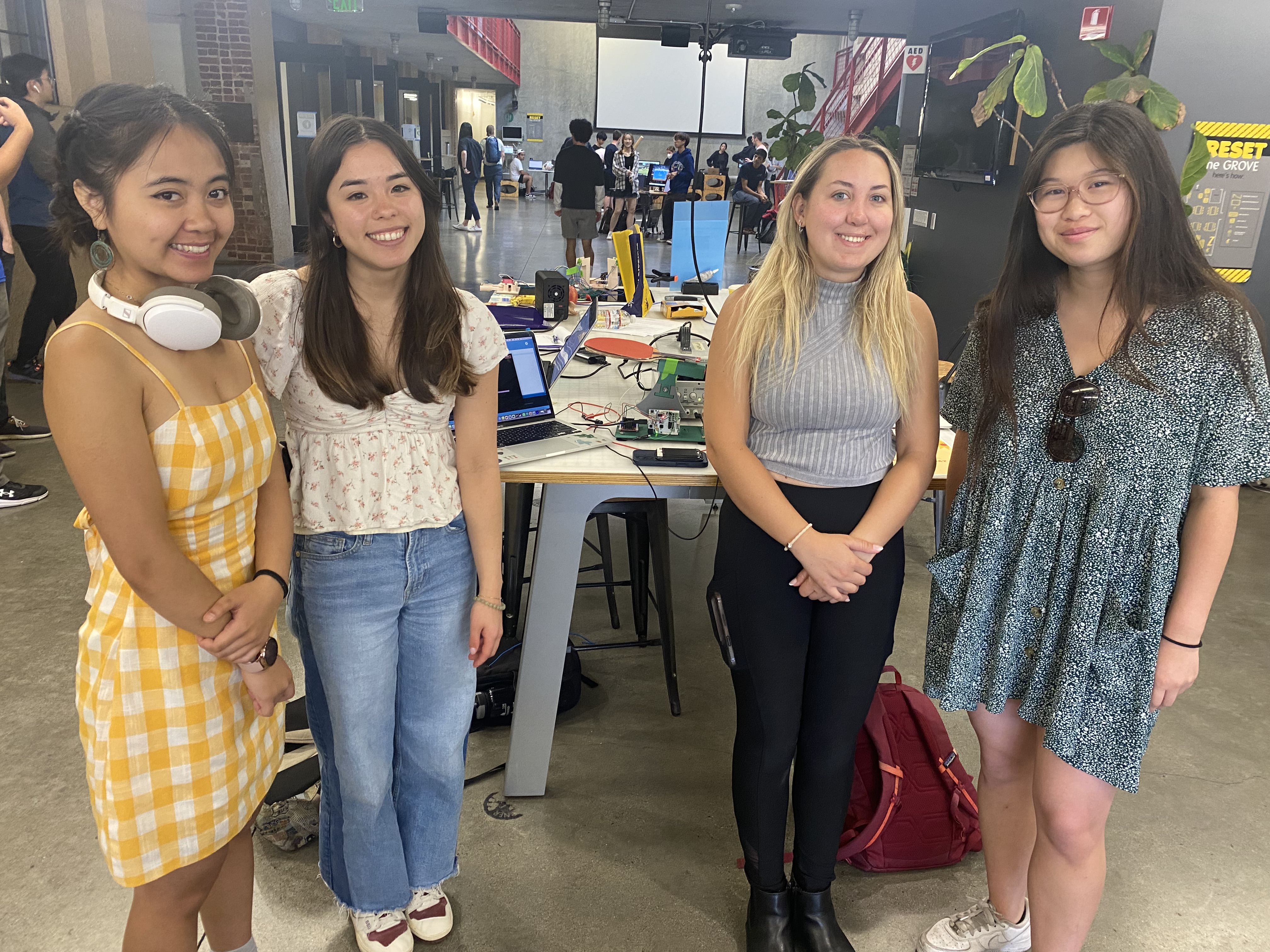
ME 327 Team 10 at the open house
On this page... (hide)
Introduction
Racket sports are a popular form of leisure, with an engaging mix of athleticism and strategy for players. However, finding courts to practice can be time-consuming and difficult without proper resources. Racket sports in virtual environments are gaining popularity as a way to practice with minimal set-up. Haptic devices play a role in enhancing realism and immersion in simulations or virtual reality of racket sports, with applications in sports training, physical therapy, and gaming. By providing feedback that mimics real-world interactions, these systems allow users to experience the physical properties of virtual objects or environments.
In order to approximate real-world experiences, particularly when hitting the ball, haptic feedback is critical. Here, we explore the use of a single DC motor to mimic the feeling of playing multiple racket sports with different types of collisions. Haptic Racket is a handle attachment that can simulate the feeling of bouncing a ball for three different racket sports: tennis, pickleball, and ping pong. In developing Haptic Racket, we modeled ball dynamics and kinematics, incorporating features such as stiffness, damping, collision response, and timing to enhance the realism of virtual racket sports.
Background
As racket sports in virtual environments grow in popularity, tactile feedback devices have become products for simulating the game. Current feedback is predominantly with vibration. Increasing the richness of tactile feedback requires large, heavy, often expensive devices [1]. The option of using a single DC motor provides an affordable alternative to simulate the feeling of hitting a ball with a racket.
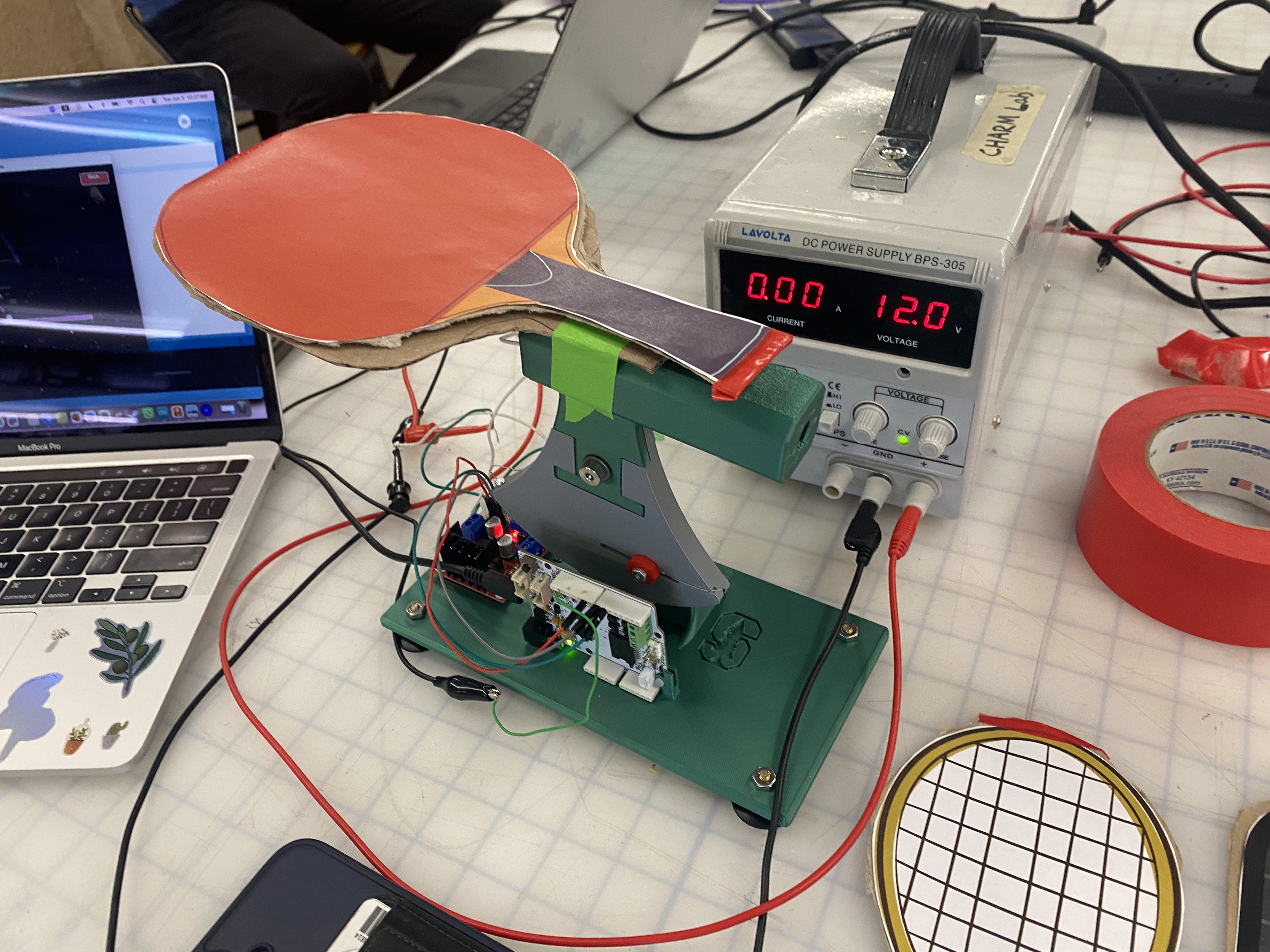
We simulated bouncing a ball with a table-anchored paddle device connected to a computer with a corresponding graphic display of the ball and paddle position. We used an MR sensor from the Hapkit to track racket position, and a single DC motor to mimic the feeling of a collision with a bidirectional pulse. Additionally, we used an Arduino UNO and L298N to control the motors and compute the collision timing.
In racket sports such as tennis, pickleball, and ping pong, differences in racket weight, material, string tension, and ball type influence the dynamics and feel of gameplay. Simulating these differences with a singular haptic device is a compelling challenge for increasing the adaptability of these devices. During the Haptics Open House (6/3) we engaged with multiple visitors who played the racket games. They were able to reflect on Haptic Racket’s distinguishable collision types and that correspond to different balls.
Prior work has explored the use of a single DC motor to impart the sense of collision and repulsion that is characteristic of racket sports [2]. Sobue et al. explore the perception of rotation direction influencing the realism of a collision, and set around a ~30ms threshold for user detection of a bidirectional motor pulse.
Methods
Hardware Design and Implementation
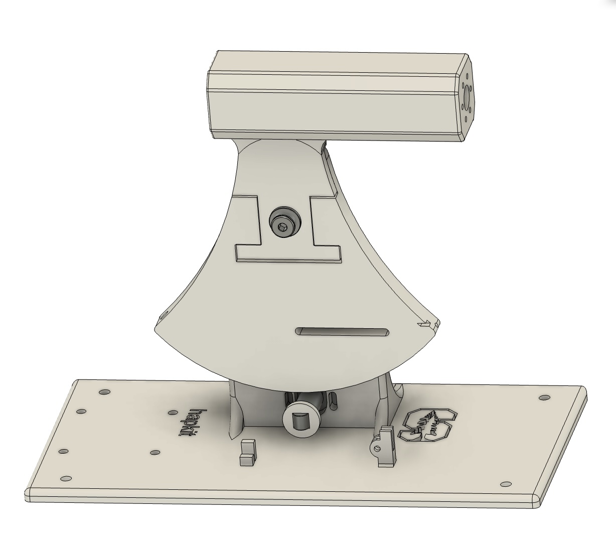
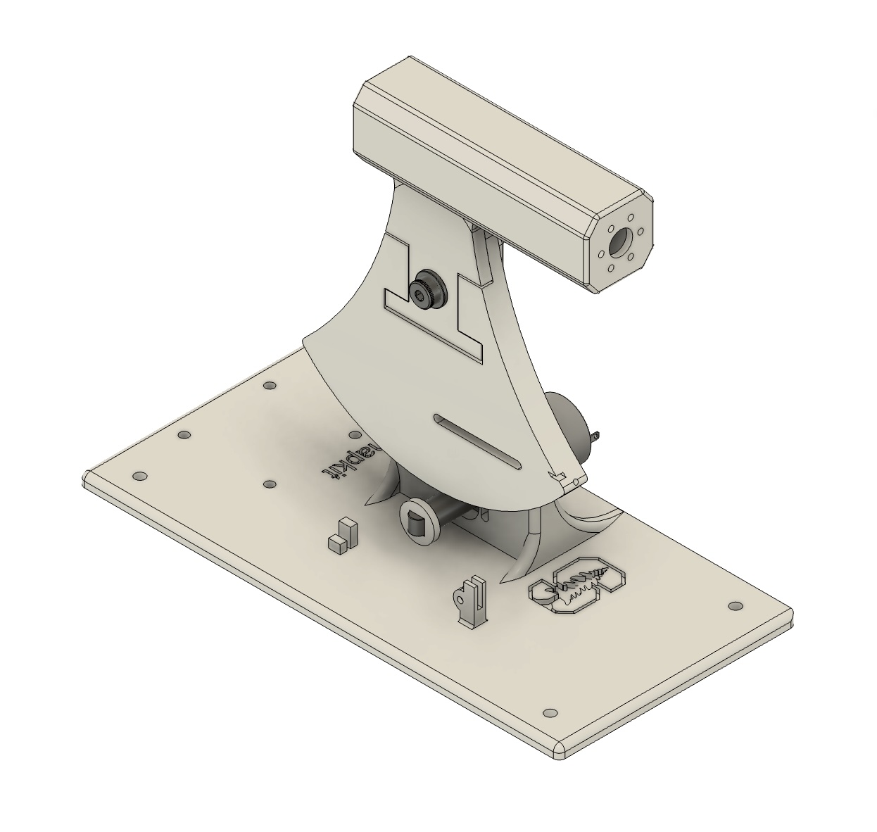
CAD Assembly of the Haptic Racket
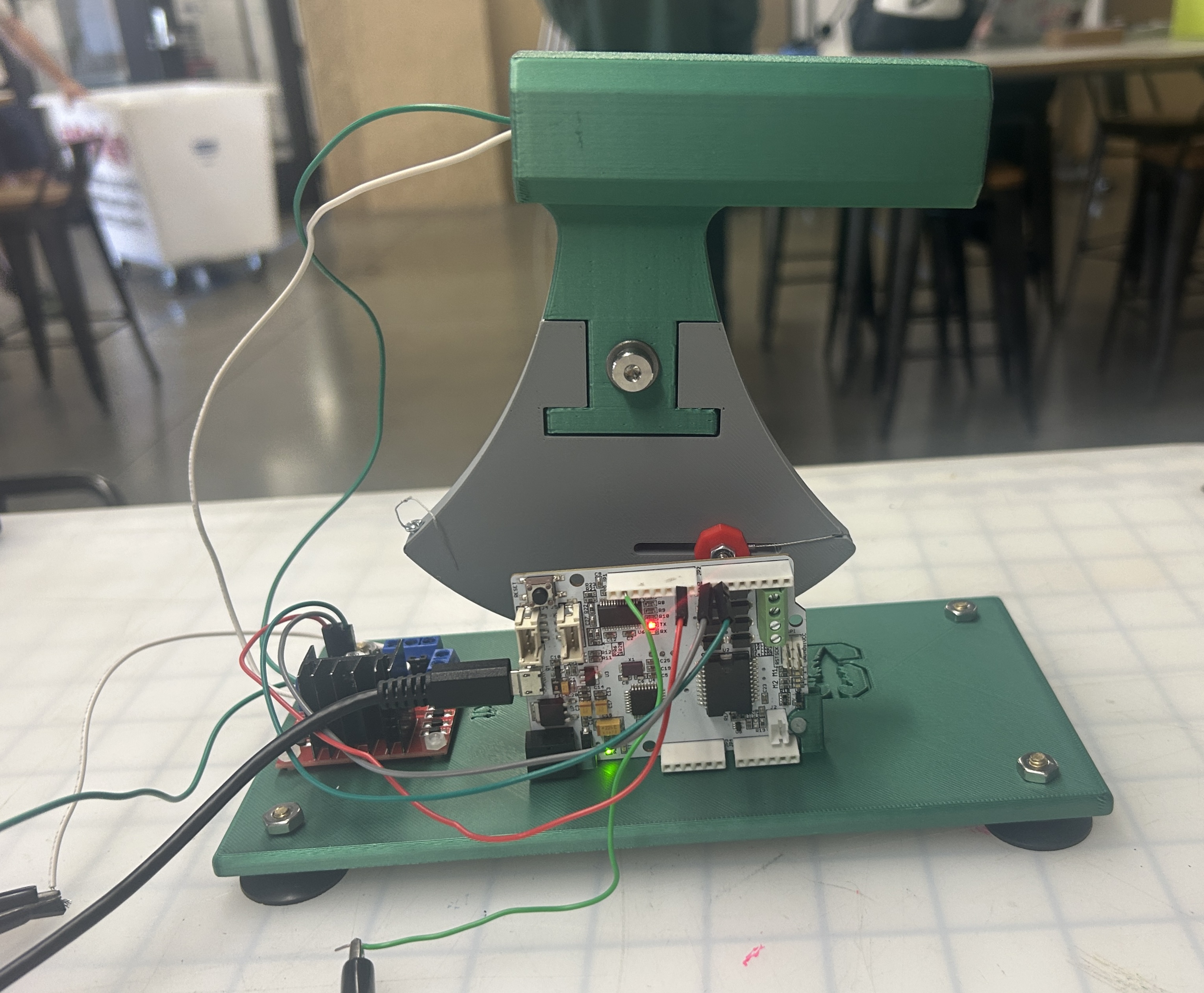
Actual Assembly of the Haptic Racket
To achieve the single degree of freedom (1DOF) actuation for our haptic racket, we started by modifying the standard Hapkit provided in class. We replaced the original handle with a custom-designed grip modeled after a pickleball paddle. This change not only makes the racket feel more realistic but also enhances user comfort. The new handle was 3D printed and securely attached to the capstan drive for stability during play.
We also reinforced the base of the original Hapkit to create a sturdier platform, ensuring that the assembly remains stable while in use. Additionally, we incorporated mounting holes for the L298N motor driver and the Hapkit circuit board for better organization and functionality.
Inside the handle, we embedded a 12V DC motor positioned to simulate collisions at the user’s grip point. This setup enhances realism by triggering the motor at the exact moment of impact. To keep things tidy and user-friendly, the wiring is routed internally, preventing any interference with the grip.
Motor Circuit
We used a L298N to drive the motor with 1A maximum current drawn.
L298N Circuit Diagram:

System Analysis and Control
Paddle Behavior
We recorded the paddle position by using a MR sensor to track the rotation of the Hapkit handle, which we mapped to vertical movement of the paddle in the virtual frame. Rotating the paddle clockwise corresponds to lifting the paddle up to hit the ball, and rotating the paddle counterclockwise corresponds to moving the paddle down in the virtual frame.
Ball Behavior - Force Model:
To simulate the motion of the ball, we initially found acceleration via force equations after modelling the ball as a spring damper system. In this model, we continuously tracked the force applied to the ball and then used acceleration (and the Forward Euler method) to approximate position. With this strategy, we were unable to model the ball with the necessary stiffness requirements and stability due to the time stepping. We found that for low K values, the ball would exhibit a sticking behavior that would result in a delay in rebound from the paddle.
For higher K values, the ball would appear to behave normally and lose energy upon the first few bounces, but would suddenly spike in energy without any movement of the paddle. This behavior was very dependent on our time step interval. We were unable to find a time step size that would work for all ball types— which have varying stiffnesses and energy losses. We ultimately decided to move to tracking ball velocity instead of starting from forces due to the lack of continuity in our system. The discrete time steps made it challenging to tune the system to have the right amount of damping/stiffness without either causing a sticking behavior or instability in ball behavior over longer periods of time.
Buggy ping pong simulation using force calculations - notice over-damped behavior and odd interaction with paddle:
Ball Behavior - Velocity Model:
The velocity model applies a constant downward gravitational acceleration on the ball, factors in air resistance, and updates the velocity accordingly (see equation).

Where vball (m/s) is the current ball velocity, g = 9.81 m/s^2, tstep (s) is the time step, and kair is a unitless scaling factor representing the impact air resistance. We elected to use kair = 0.0001 to make the simulation as realistic as possible (any higher and it would noticeably slow the movement of the ball). After updating the velocity to factor in gravitational acceleration and air resistance, we found ball position:

To handle velocity and position changes due to a collision with the paddle/racket, we would check if xball<= xpaddle and if the ball’s velocity was negative, indicating that the ball was moving in a downward direction. If these conditions were satisfied, we would constrain the ball to the same height as the paddle, reverse the velocity, and model energy loss by reducing the ball’s rebound velocity by a scaling factor, kball, that changed depending on what racket sport we were modeling. We also factored in any speed boosts provided by the velocity of the paddle by adding in the paddle speed if it was greater than zero.

This allowed us to realistically simulate the behavior of a ball bouncing off of a paddle. For ping pong, we used kball = 0.1 because the collision between a ping pong ball and paddle is the most elastic of the three, so we wanted it to have the least amount of energy loss. For tennis ball collision with a tennis racket, we used kball = 0.2 because we wanted to factor in the elasticity of the rubber shell inside of the ball while also increasing the energy loss compared to the ping pong ball. Finally, for pickleball, we modeled it to have the largest energy loss in each collision, with a kball = 0.3.
Modeling Impact:
To create a sensation of impact, we built off of ideas from “Presentation of Hitting Sensation to the Racket by a Single DC motor Embedded in a Handle” (Sobue et al. 2024) and used a single DC motor embedded into the handle of our hapkit. For each racket sport, we tuned two variables—impact duration and motor speed—to create a distinct haptic representation of collision. The paper recommended using two consecutive 10 ms pulses in opposite directions to create an impact sensation. We used a L298N motor driver to control the direction and PWM of the DC motor, varying PWM to change motor speed and control the intensity of the impact sensation.
For ping pong, we selected an impact duration of 10 ms per direction and a 20% duty cycle because it has the most elastic impact and is the lightest ball. We wanted to minimize the sense of repulsion during the impact to mimic the light weight, and replicate the minimal energy loss in the collision by making the impact duration short.
Ping pong paddle and ball:

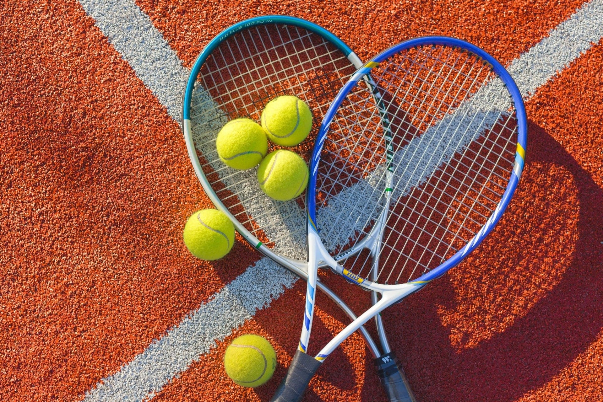
For tennis, we selected an impact duration of 15 ms per direction and a 86% duty cycle. We selected a higher duty cycle to represent the heavier mass of the ball and lengthened the impact duration to reflect the deformation of the tennis racket strings around the ball upon collision. We wanted to model a springy and elastic collision, so we chose intermediate values to reflect the moderate energy loss.
Tennis racket and ball:
For pickleball, we selected an impact duration of 25 ms per direction and 100% duty cycle because the collision has the most energy loss and we wanted to capture the duller, less elastic collision by using a longer impact duration. Because the pickleball paddle is more rigid than the tennis ball racket strings, the collision feels harder, which is why we used a 100% duty cycle, despite the tennis ball having a larger mass.
Pickleball paddle and ball:

Processing
Overview
The Processing code is responsible for simulating the virtual environment which includes the racket, ball, and numeric/visual game metrics. The Processing code relies on position and velocity outputs from the Arduino. Paddle and ball position information was printed out in the serial monitor to send it to Processing using serial communication. First, the position from the handle/ball as well as the ball velocity are all calculated using a simple dynamics model simulation occurring on the Arduino. Then, these values are sent as outputs to the Processing code for parsing, mapping, and visualization into the virtual environment.
Arduino-Processing Serial Communication
The key component for visualization was serial communication. Serial communication is essential for the Haptic Racket because it enabled seamless data transfer between the Arduino Uno microcontroller, which captured the real-time positions of the racket and ball. By using serial communication, the Arduino could efficiently send position data to the computer, allowing the Processing application to update the visual representation of the racket and ball in real time. This direct exchange of information ensured that the physical interactions with the haptic device were accurately reflected in the virtual simulation, creating a more responsive and immersive user experience. Without serial communication, integrating the hardware and software components of the project would have been far more complex and less reliable, especially since serial programming is straightforward and robust on Arduino devices.
The following function titled serialEvent(), was used to read string outputs from Arduino, parse them into variables (ie. handlepos, ballpos, ballvel) to be used for visualization. In addition to kinematic quantities for the racket/ball, the function also takes the bounce count as an input to determine when a bounce was just triggered. This updates Processing’s visual display of the bounce count as well as triggers a change in racket color once the bounce occurs. This rainbow-color changing racket is an added feature that does not add functionality to the system but is an ode to visually appealing aesthetics that seek to gamify our virtual environment as well as celebrate the fact that it is pride month!
Rendering Opening Screen
In order to give the user an introductory game-like experience and to enhance the intended purpose of our project, we created an initial game screen that was interactive and visually appealing. To do this, we initialize the game with a screen that says “Haptic Racket!” in bold letters with layered text of varying colors to create a “glow effect.” The initialization screen draws 3 distinct buttons titled Tennis, Ping Pong, and PickleBall to allow the user to choose the corresponding ball type that was #defined in Arduino. The color of each button was intentionally chosen to match the ball type. In addition, the bottom of the screen provided instructions for game play for the user. The instructions read: Experience realistic haptic feedback with each ball type. Watch the racket change colors when the ball bounces! Press ‘D’ to toggle debug information.” The added debugging feature allowed the programmer to see the real-time Arduino outputs and compare to the game play screen outputs for position/velocity. This debugging feature allowed the Processing programmer to see how well the code was mapping raw Arduino outputs. The following function, initScreen() was used to convey the aforementioned info.
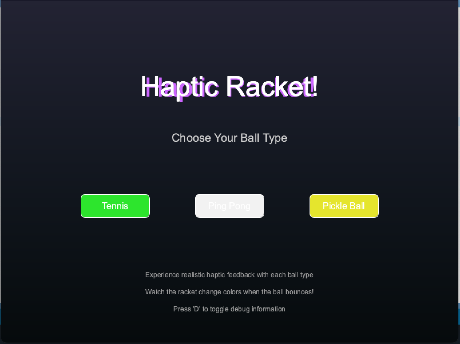
Intro Screen for Game
Rendering Play Screen
The game/play screen depicted the actual movements and interactions of the ball and racket as well as various game metrics and added visually aesthetic, interactive features. Thus, this screen was the most programmatically involved. To help facilitate programmatic flow between all of the responsibilities of the game screen, we used helper functions. These helper functions are included in the main function playScreen() and are as follows: drawPlayBackground(), drawBackButton(), drawBallTrail(), drawEnhancedBall(), drawEnhancedRacket(), drawInfoOverlay(), and updateRainbowEffect(). In addition to these helper functions, the playScreen() function does have blocks of code that check if certain conditions are met. For example, playScreen() checks when a user either presses the back button to return to the initial screen or the enter or space key is pressed when the user wants to end the game. The playScreen() function also is responsible for mapping the ball and racket positions and adding the ball-colored trail once the ball is bounced up or down. The most important condition that the playScreen() function checks for is that the ball does not go through the racket. We were having substantial difficulty ensuring that this interaction was seamless. We experienced scenarios where the ball would bounce on the top racket at first, go through it, then bounce back from the ‘floor’ of the screen to the bottom of the racket. Other odd scenarios included the ball bouncing in mid-air much too high above the racket and the ball bouncing inside the racket itself. To fix these issues, we implemented a check for if the bottom of the ball surpasses the top of the racket, then the new ball position is always just above the racket.
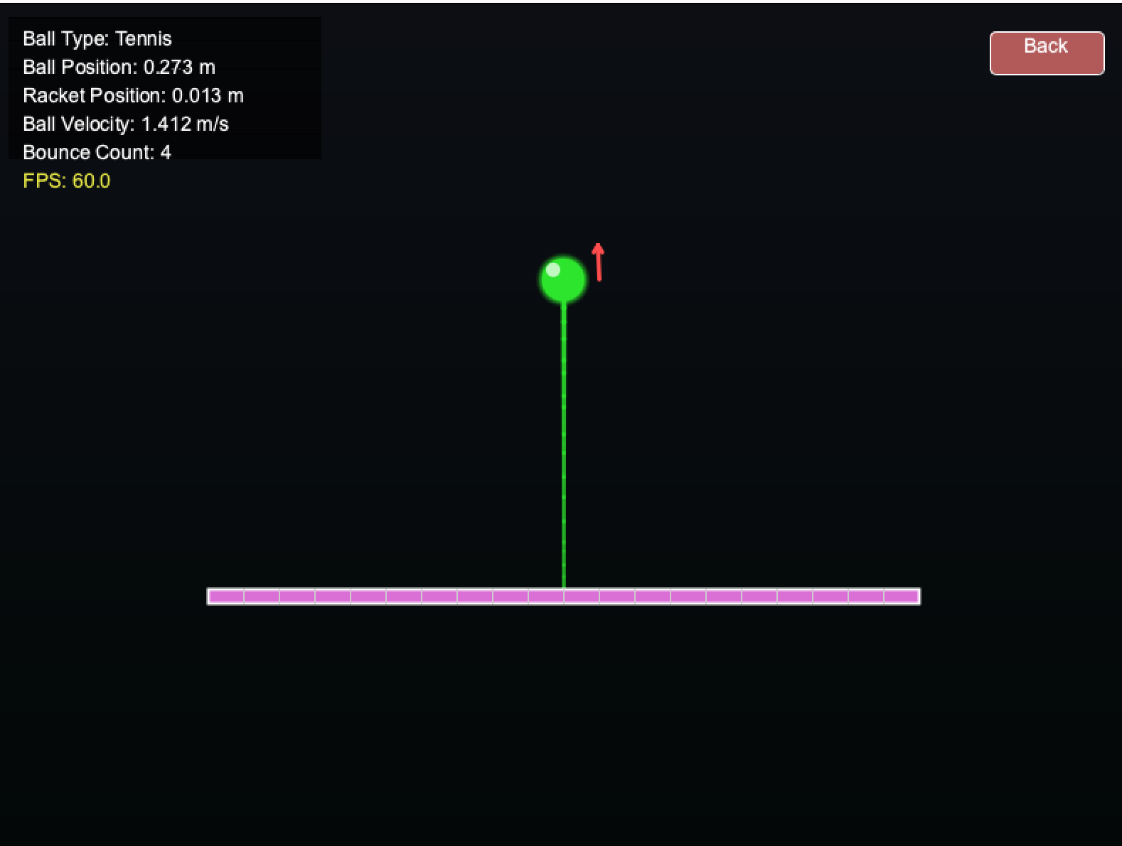
Gameplay Screen
Rendering Game Over Screen
In order to account for any errors that our program was encountering visually, we implemented a game over screen. For example, if the user shot the ball into oblivion or caused the racket to fall below the screen, we implemented a visual reset screen to indicate to the user the simulation must be restarted. The screen looks for any key presses on the spacebar or enter key and displays large red text that says ‘Game Over.’
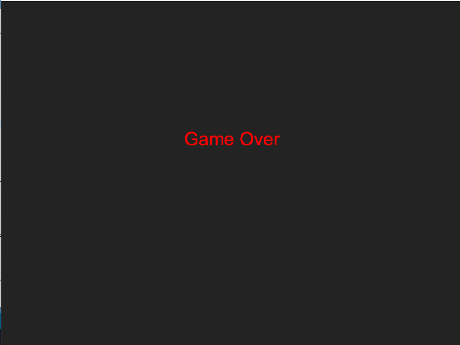
Game Over Screen
Aesthetics
The features that did not add to the functionality of the game but were nice-to-haves that we ended up implementing included the rainbow color-changing racket, ball trace, and velocity tracking.
Color-Changing Racket
The racket changed colors upon impact which was another indicator (in addition to haptic feedback) that the user had successfully bounced the ball. The function drawEnhancedRacket() and UpdateRainbowRacket() were used to track the racket’s color. Whether the ball came into contact with the racket was tracked by the main playScreen() function.
Ball Trail
The ball had a visual line that varied in length and direction to match the speed and direction of the ball mid-air. To visualize this trail, we stored the trail positions as a vector in an array of y coordinates. This array was constantly changing to match the ‘trail’ of the ball’s motion and was calculated and updated upon each new ball position output. These coordinates were then translated into pixel locations whereby each pixel was colored according to the motion of the ball’s trace. The ball’s trail length was 30 pixels. So, every time the ball moved, its location of its trail was tracked based on the ball position and corresponding pixel locations.
Velocity Arrow
In order to indicate the direction of the ball (positive = blue and negative = red) velocity, we implemented color-changing, directional velocity arrows. The arrows used a similar concept to the Ball Trail feature, with the exception of being offset from the center of the ball. The arrows were located next to the ball. Another exception was the color-changing feature, which indicated the velocity direction. Depending on the sign of the velocity calculation, the arrows switched from red to blue. Additionally, the length of the velocity arrows were proportional to the magnitude of velocity which again, used a simple map function as the abs(ballVel) as the main input.
Game Metrics
In the function drawInfoOverlay(), the following metrics were reported in real time for the user to see: Ball Type, Ball Position, Racket Position, Ball Velocity, and Bounce Count. These added features, again, did not add to the functionality of the overall main project’s goal but were helpful for debugging and determining where the ball/racket were at all times. It also gave the user a sense of relative timing if the ball was shot up far too high and the user was curious about when it was likely to come back down again. These metrics were the mapped locations that were calculated from the Arduino code. Raw values could be displayed as part of the debugging process, if the user pressed the ‘D’ key.
Demonstration / Application
Ping pong simulation using velocity calculations:
Results
We had 43 users at the Haptics Open House (6/3) evaluate each of the balls on a Likert scale. On this 7 point scale they rated how realistic each of the balls felt upon impact from “not at all realistic” to “very realistic”.
Pickleball: 5.92 / 7.0
Ping Pong: 6.34 / 7.0
On balance, ping pong was rated (and verbally expressed) as the most realistic of the simulations. The ball was expressed with the shortest collision duration and lightest intensity, perhaps resulting in minimal rotation direction pulse detection. Additionally, because motor PWM is the smallest compared to pickleball and tennis (sports with more massive balls), the motor pulse intensity was more distinct from the other two sports, perhaps contributing to user’s preference for the simulation.
Future Work
From the users in the open house, individuals noted that the ping pong simulation felt the most realistic. The tennis and pickleball felt simulated due to the decreased intensity of collision to the actual event. In future work, we would explore the use of a 24V motor so that the impact and repulsion would be more distinct for these higher power collisions. Additionally, we would explore adding an offset mass to the motor to increase the feeling of rotational inertia. Additionally, expanding this device beyond the hapkit set-up with the MR sensor, and using an accelerometer or IMU would help to track the paddle motion with realistic swings. This would allow users to play the racket sports as games with full swings, rather than just bounding the ball on a paddle in 1 degree.
Acknowledgments
We would like to thank the ME 327 teaching team: Professor Allision Okamora, Ryan, and Teo. Additionally, we extend our gratitude to individuals who support the GSE makery, for providing print materials for our custom parts.
Files
Code and drawings should be linked here. You should be able to upload these using the Attach command. If you aren't willing to share these data on a public site, please discuss with the instructor. Also, in this section include a link to a file with a list of major components and their approximate costs.
1. Haptic Racket Arduino Code: Attach:Team_10_Haptic_Racket.zip
2. Processing Code: Attach:Team_10_Haptic_Racket_Processing.zip
3. Haptic Racket Parts List: Attach:HapticRacket_PartsList.pdf
4. Haptic Racket Engineering Drawings: Attach:Handle_DWG.pdf
5. Haptic Racket Modified STEP files: Attach:HapticRacket_handle.zip
Attach:HapticRacket_base.zip
References
[1] Inoue, D., Nishimoto, K., Nakamura, T., Fukuda, K., Narumi, T., 2023. HapReel: A Racket-shaped Haptic Display Controller for Presenting Vibrotactile and Force Feedback through Fingertip Deformation, in: SIGGRAPH Asia 2023 Emerging Technologies, SA ’23. Association for Computing Machinery, New York, NY, USA, pp. 1–2. https://doi.org/10.1145/3610541.3614583
[2] Sobue, M., Kato, S., Mizoguchi, I., Kajimoto, H., 2024. Presentation of Hitting Sensation to the Racket by a Single DC motor Embedded in a Handle, in: 2024 IEEE Haptics Symposium (HAPTICS). Presented at the 2024 IEEE Haptics Symposium (HAPTICS), pp. 244–250. https://doi.org/10.1109/HAPTICS59260.2024.10520849
[3] Ping pong ball and paddle image: https://www.advancedsciencenews.com/the-future-of-athletics-smart-ping-pong-paddles/
[4] Tennis ball and racket image: https://magazine.fortevillageresort.com/sport/all-about-tennis-and-its-basic-rules/?lang=en
[5] Pickleball and paddle image: https://www.genre.com/us/knowledge/publications/2023/august/pickleball-more-than-just-the-fastest-growing-sport-en
Appendix: Project Checkpoints
Checkpoint 1
We plan to design a 1 DOF haptic device, and have a virtual environment the device will be operating in. In our case, the device is a modified Hapkit that will look similarly to a racket. We will make this racket reconfigurable for different sports. We will also be creating a changing virtual environment that mirrors the real-life racket attachment.
What has been done so far: (1) motor selection (2) preliminary CAD design (3) pseudocode and preliminary Arduino code.
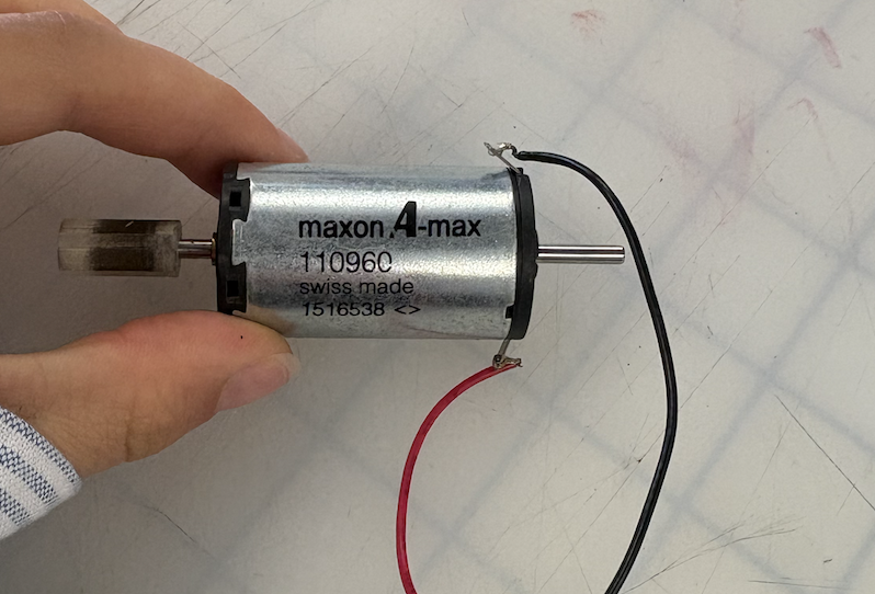
(1) Based on our selected research paper, "Presentation of Hitting Sensation to the Racket by a Single DC motor Embedded in a Handle," we have decided to use a DC motor to replicate the sensation of hitting a ball with a racket (Sobue et al., 2024). We have decided to look for a motor with the following qualifications: 1. No load speed of >5000 RPM to allow the motor to create a distinct and sharp sensation of impact 2. Stall torque of >30 mNm to generate enough torque to create a sense of repulsion
We found a motor to borrow from CHARM lab that meets these qualifications. The motor is a maxon A-max (part #110960). It has a no load speed of 8190 RPM and a stall torque of 80.2 mNm. See the product datasheet here.
Motor Image:
(2) Below is an image of our preliminary CAD model for the handle attachment. This component is designed to interface with the Hapkit by securing to the sector arm using a shoulder bolt through the lower mounting hole. The cylindrical handle features a central cutout where the motor will be housed. In future iterations, we plan to implement an adjustable mechanism to shift the center of mass. This will allow us to simulate the weight distribution and feel of various racket handles more accurately.

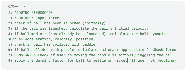
(3) The goal of the following code is to be able to create a bouncing ball effect on the user (for this initial code, only a single ball type will be tested). The user will first start with a stationary ball on the paddle. The motion of the user moving the modified hapkit handle will initiate the movement of the ball. The user must move the handle in an upward motion to enact a force onto the model, launching it into the air. Once the ball has left contact with the paddle, the dynamics of the model will be most useful here. The timing and the height of the ball will depend on the ball's initial velocity which comes from the user's upward thrust and the ball type. Once the ball completes its upward and downwards trajectory, the ball will contact the racket. The magnitude of the feedback felt by the user upon the ball-racket collision will also depend on the ball type and downwards velocity. The next part of the code will be to model the bouncing effect for the ball post-collision, while also still taking the user's motion into consideration. For example, if the user no longer moves post-collision, the ball will simply bounce up and will slowly settle as the racket's damping will begin to have a larger and larger effect. However, if the user continues to interact with the ball such that the ball is being constantly juggled mid-air, the Arduino code must accommodate these constant collisions with the correct feedback forces.
Below is an image of our pseudocode for the Arduino program.
Below is an image of our preliminary Arduino code written using the Google docs code block tool:


Checkpoint 2
Few sentence summary/description about what we did overall...
What has been done so far: (1) CAD refinement and assembly (2) preliminary motor and feedback/vibration testing (3) analytical dynamics modeling (4) initial virtual environment design using Processing code.
(1) We’ve developed a few variations of the handle design. Initially, it was modeled with an extended length, and the motor was simply press-fit into place. In the current iteration, mounting holes have been added for secure motor installation, and space has been allocated for a counterweight if needed. The current CAD assembly is shown below. The handle is shaped to resemble that of a pickleball paddle, with the motor embedded inside to provide haptic feedback that simulates the sensation of hitting the ball.
(2) We are using a 12V power supply with a L298N motor driver to control our motor. Drawing inspiration from Sobue et. al (2024), we are simulating the sensation of impact by cycling between the motor starting off, rotating in one direction for 10 ms, then immediately rotating in the other direction for 10 ms. The motor's motion and waveform looks like this:

We were able to modify the intensity of the sense of impact by varying the PWM of the motor and decreasing the speed for the duration the motor was on. We tested a 20%, 60%, and 100% duty cycle on three members of our team, who all reported that there was a distinct and perceptible difference in the impact sensation at each PWM frequency.
(3) In the screenshot below, we summarize the ball dynamics as modeled by a spring-damper system.
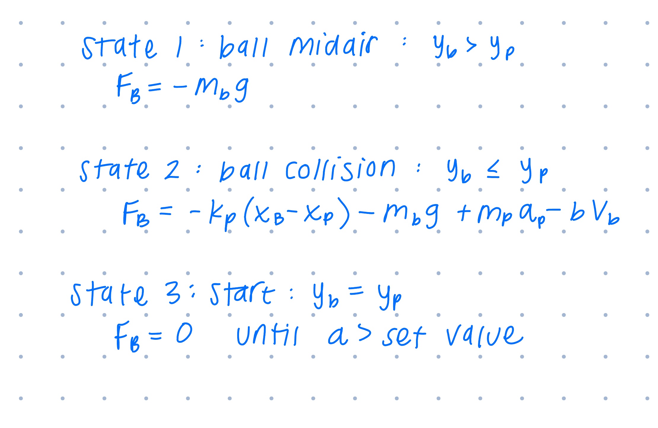
(4) Below is a short video of our virtual racket and ball simulation. Before the mouse is in contact with the virtual environment screen, the racket and ball have an initialization. The environment initiates with the ball and racket as stationary. Once the user hovers their cursor over the virtual environment, the racket and ball follow the cursor. The juggling of the ball begins when the user moves the racket either up or down. Then, the ball begins to bounce upward until either settling down (if the racket no longer in motion) or continuing to bounce at an increasing or constant height. This environment is meant to emulate our system (though with rudimentary graphics which we plan to improve eventually). The user's cursor motions will be replaced with inputs from our modified Hapkit handle.
Below is a video of the virtual environment and the user's juggling.

