

2025-Group 11
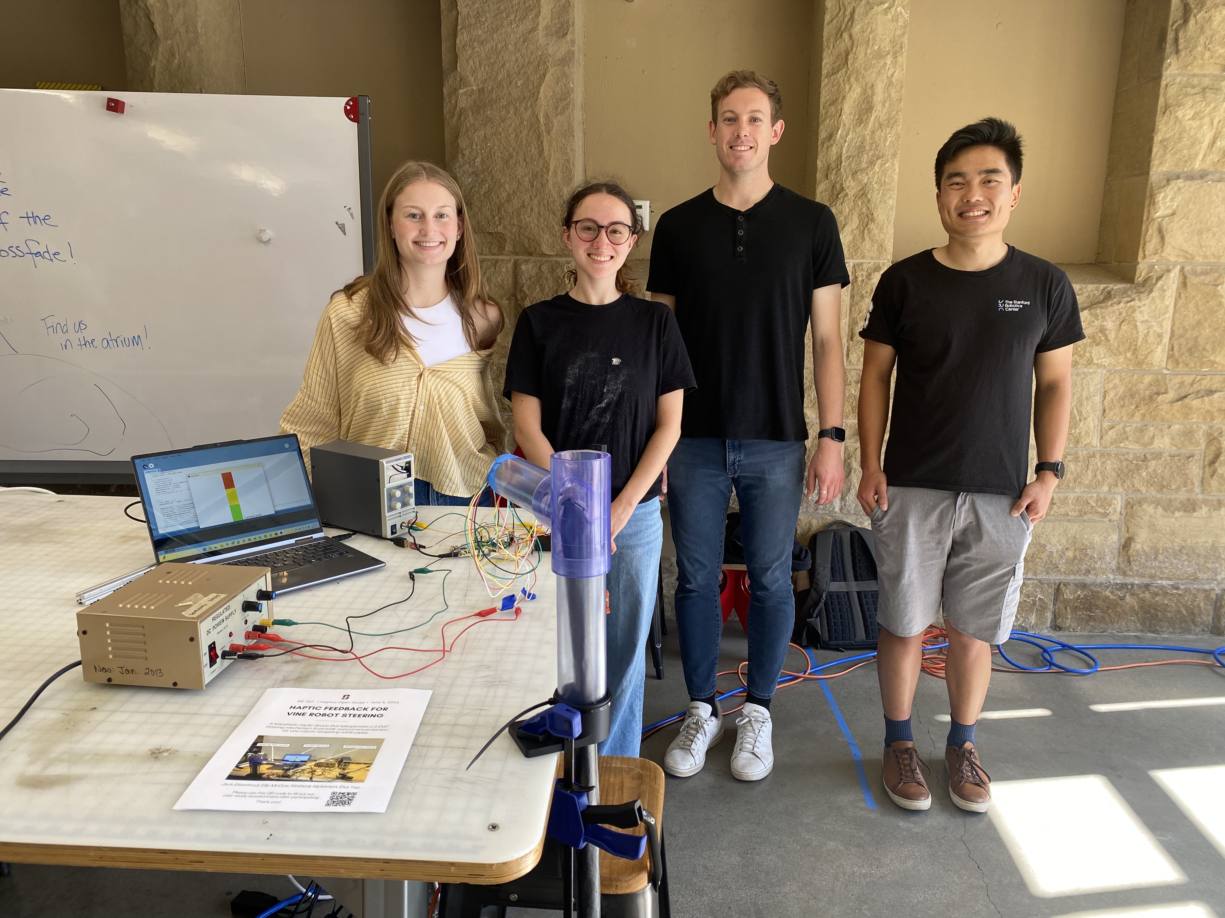
Group photo with haptic device on demo day.
Vine Robot Steering Teleoperation
Project team member(s): Elle McCue, Elvy Yao, Jack Eisentrout, Kimberly Nickerson
We developed a haptic feedback steering interface for a vine robot navigating within pipes. The system enables teleoperation and provides force feedback when the servo at the tip of the robot draws excess current. Currently, operators of the vine robot can easily irreparably overcurrent the servos as they are steering through bends. Our custom-designed fixture mimics the robot�s two degrees of freedom, with one motorized axis delivering resistive torque and one passive axis. We conducted user testing to compare steering performance with and without haptic feedback. Although servo motor current reduction was not statistically significant, participants reported improved intuitiveness and confidence with feedback enabled. This system improves upon a previous vine robot steering GUI and could enable safer, more effective navigation for vine robots in real-world environments. This project will likely continue within CHARM Lab�s vine robot research group for in-pipe navigation.
On this page... (hide)
Introduction
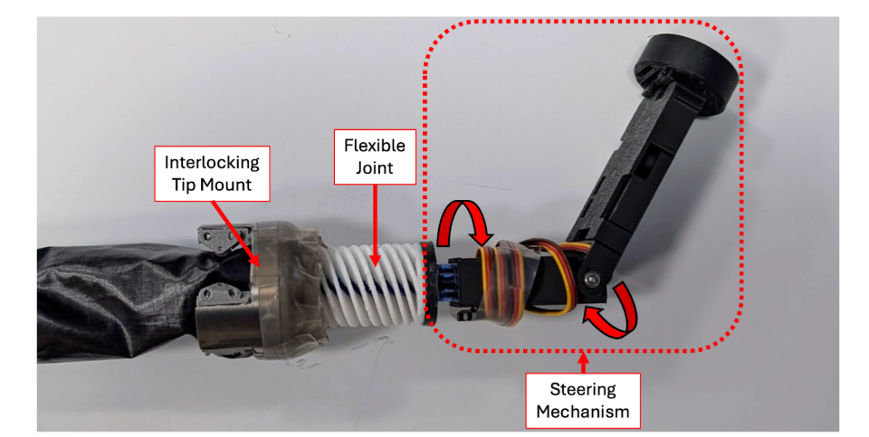
Vine robot tip and steering mechanism
We chose to design and test a haptic feedback steering mechanism for a vine robot navigating within a pipe. Currently, the vine robot navigates based on visual feedback from a camera at the tip of the robot and a slider on a GUI used to rotate motors for the 2-DoF steering mechanism. This method is not ideal because it does not incorporate current sensing for the motors, which can become damaged due to overcurrent when trying to rotate into positions that aren�t achievable (Ex: when interfering with a wall). Our haptic feedback device consists of a 3D printed structure and a motor which will provide resistive torques when high currents on the steering mechanism motors are detected. The feedback from this motor will help indicate the path of least resistance when navigating through turns within a pipe to minimize the risk of damaging the steering motors (failure mode). This project has the potential to be used in further vine robot research and applications within Stanford�s CHARM lab.
Background

Vine robot growth mechanism
Vine robots are soft, everting bodies with an internal rigid Steering-Reeling Mechanism[1]. These soft robots move through environments through growth at its tip. Typically, vine robots are controlled by one of three steering mechanisms: teleoperation, advanced route planning, or autonomous control. These control strategies are often aided by visual feedback from a camera at the tip of the robot. Due to its flexible nature and ability to navigate through cluttered and complex environments, researchers have investigated the use of vine robots for numerous applications, including archaeological digs, colonoscopies, search and rescue, and monitoring constricted environments [1 - 5]. However, most research is currently limited to in lab settings.
In order to deploy vine robots in out of lab settings, researchers believe that intuitive human-in-the-loop teleoperation is key for navigation in dynamic environments [3]. Typically a GUI is used to teleoperate the vine robot steering mechanism, and in some applications a joystick has been used [3]. One common issue with the current teleoperation procedures is that the vine robot motors can become damaged due to overcurrent. This happens when the user tries to steer the robot into positions that aren�t achievable. To make the steering more intuitive for an operator, we are proposing that haptic feedback be integrated into the user interface.
In pedestrian and vehicle navigation and steering tasks, haptic feedback has been shown to positively impact task performance [6-7]. For example, providing force feedback to vehicle steering wheels can reduce the time it takes for drivers to notice obstacles or other steering problems and correct for them [6]. Along this vein, applying haptic force feedback in the context of vine robot operation, may help users avoid steering the robot into obstacles, or environmental boundaries that are likely to cause the motor to overcurrent and the system to fail. The purpose of this project is to map the existence of walls in the real-world environment the robot is navigating to haptic feedback on the steering interface to help prevent the motors from drawing too much current and malfunctioning.
Methods
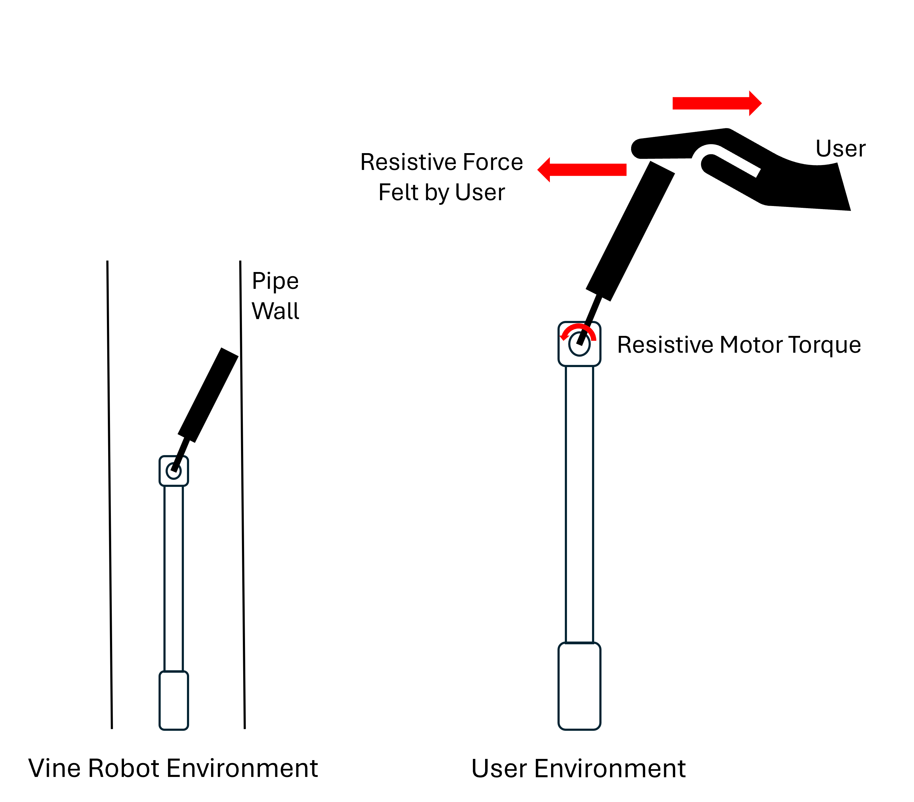
Schematic of vine robot teleoperation
The haptic feedback interface consists of a teleoperation fixture with one powered degree of freedom and one unpowered degree of freedom. The two degrees of freedom are the same as the robot tip for intuitive steering. The user handle is similar to the extrusion on the tip of the robot that holds the camera. To operate the vine robot, the user manipulates the orientation of the user handle which teleoperates the tip of the robot. Force feedback is provided through current sensing on the distal servo motor. The direction of the force feedback indicates to the user which direction to steer in order to reduce current in the distal servo motor. When the steering mechanism encounters a physical wall, the force feedback to the user will simulate a virtual wall with high stiffness.
Hardware Design and Implementation
The primary design driver for our teleoperation fixture is for it to be intuitive to the user. To accomplish this, the fixture has two degrees of freedom - just like the steering mechanism on the vine robot. The first degree of freedom is controlled by a DC motor such that kinesthetic haptic feedback can be provided to the user. The user interfaces with the fixture via a handle oriented perpendicular to the motor shaft such that the handle motion corresponds directly with the rotation of the steering mechanism. The handle is gripped by at least two fingers (Ex: thumb and index finger) of the user�s right hand. The second degree of freedom does not incorporate force feedback as it is significantly less likely to cause overcurrent issues. Therefore, the design is simply a rotating shaft supported by two bearings. Each rotation, either by the motor shaft or the bearing shaft, rotates an in-line potentiometer to record angular position. The fixture is sized to fit comfortably on a desk or another flat surface, and can be held in place by either a clamp or the user�s left hand.
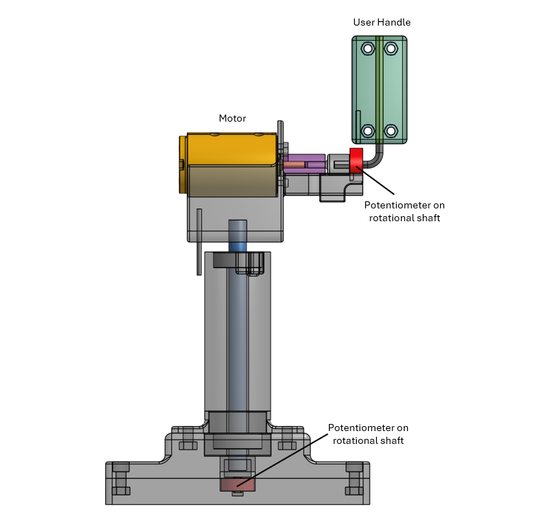
CAD of user handle[<<]]
Electronics and code
The overall communications between our user fixture controller (Hapkit Arduino Uno) and the vine robot controller (Arduino Micro) is summarized below and demonstrated in the following flow chart and circuit diagram.
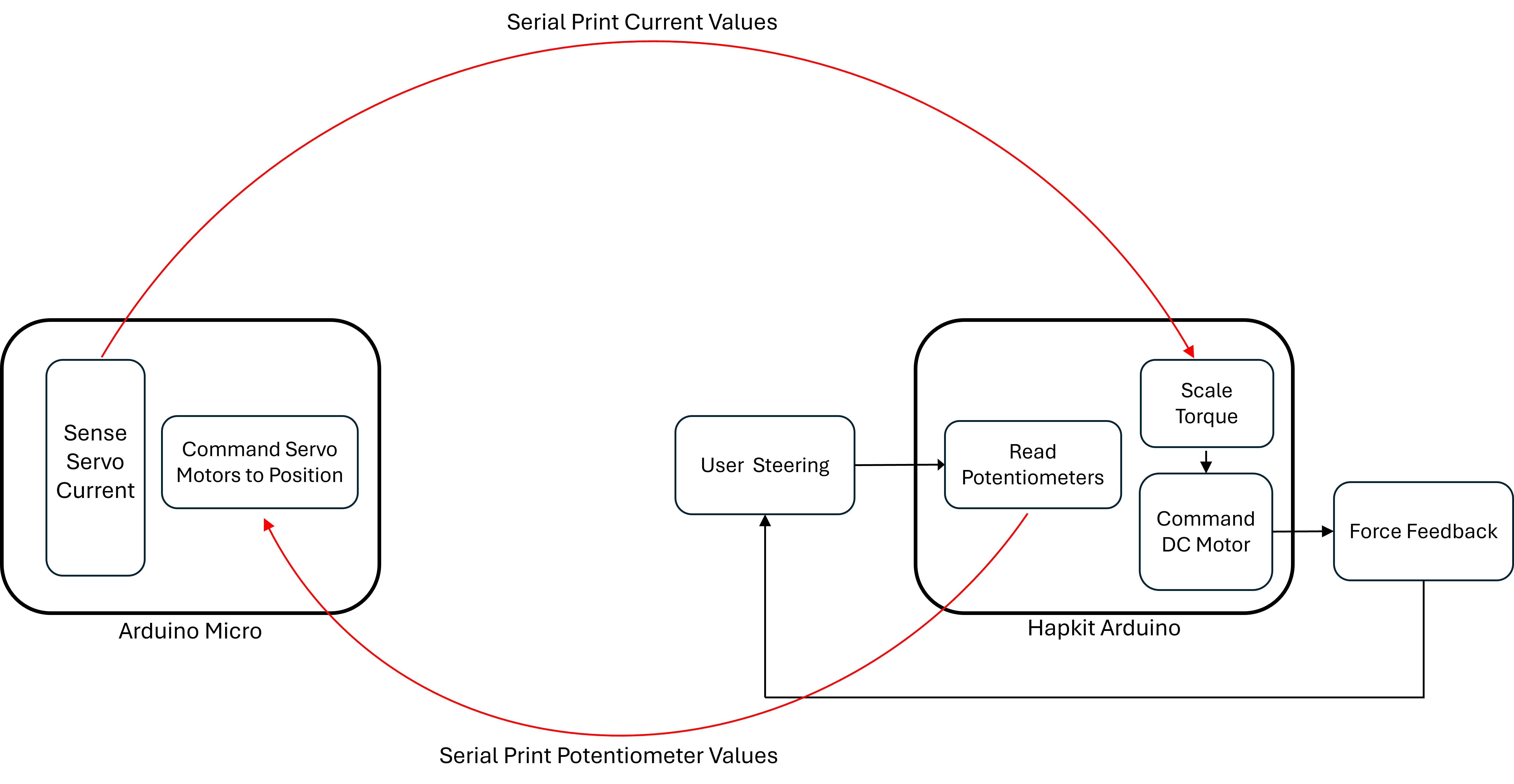
Command Flow Chart
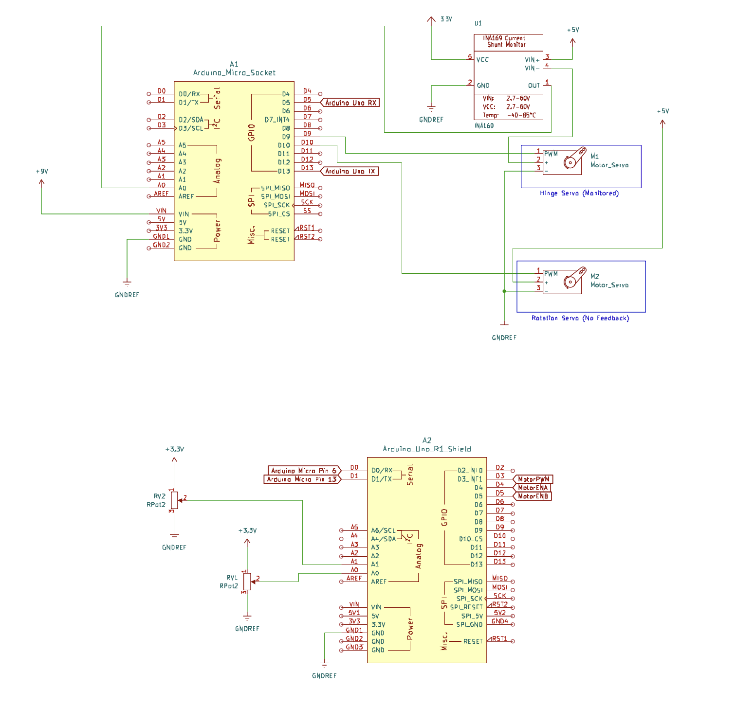
Circuit Schematic
An important part of the code is the force direction algorithm. The force direction algorithm on the Hapkit side is needed because the Arduino Micro only provides current values to the Hapkit side and no other information. This means that the direction the force needs to push on the user handle side must be determined by handle movements. A summary of the algorithm is as follows:
- Tracks the handle�s angle over time by saving previous 11 values
- Calculates average velocity over those 11 values
- Determines direction for the force
- Checks servo current before changing direction
- Change motor direction pins to sent direction
Virtual Environment/UI

Animation of user interface displaying
current rating
To ensure correct perception of the haptic feedback, we added a graphical interface to the vine robot steering setup. This UI was coded in processing, and consisted of a current meter that output the level of current the vine robot servo motor was experiencing. The current level displayed on the UI corresponds to the scale of the force feedback the user should feel.
Results
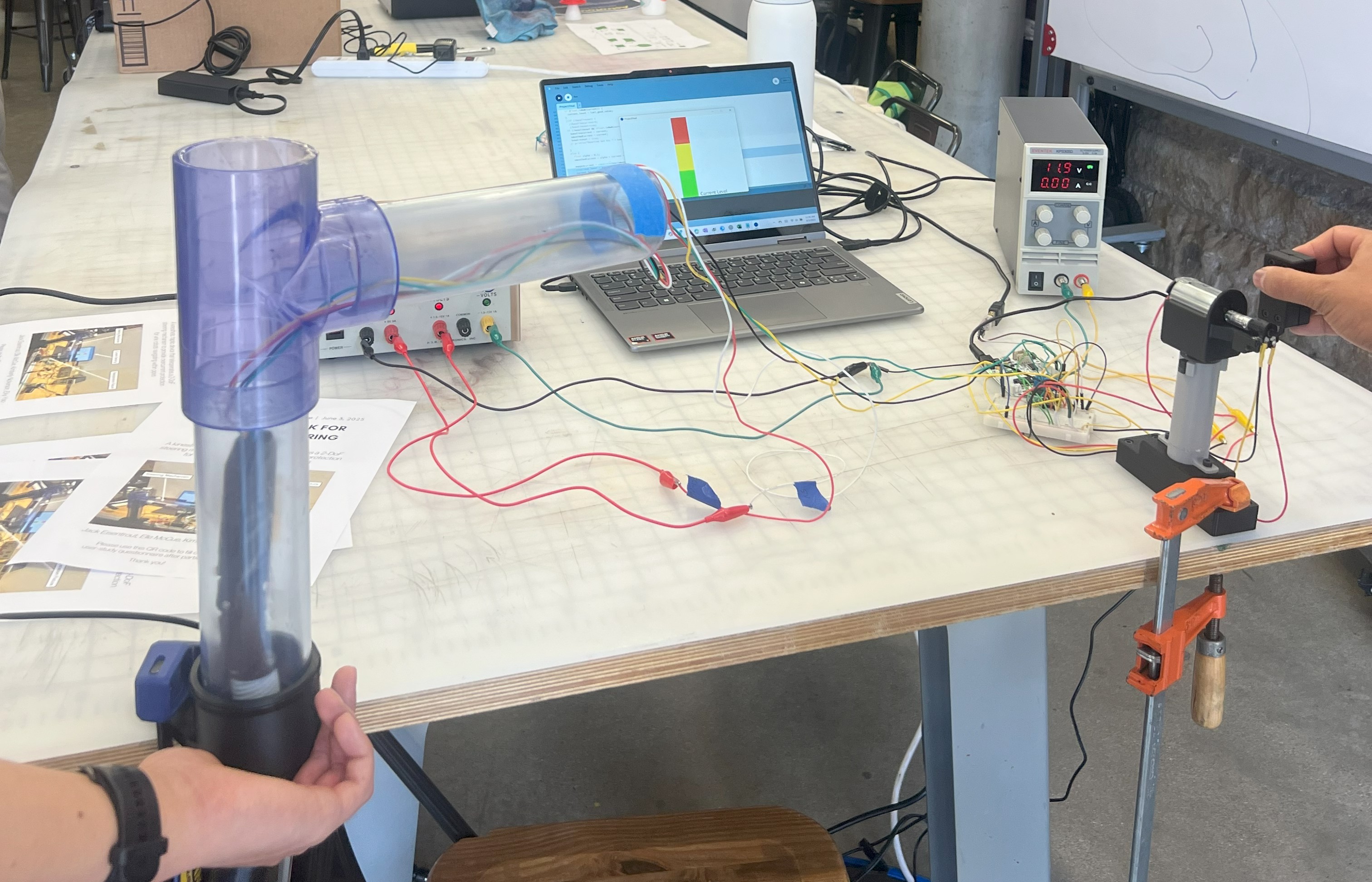
User study test setup
In order to determine how haptic feedback impacts the task of steering the vine robot, we gathered quantitative and qualitative data from 8 users. We asked each participant to steer the robot using the user handle through our test fixture for two trials. For one trial, haptic feedback was enabled on the user handle, and for one trial there was no haptic feedback. The order of these trials was randomized across participants.
During each trial we recorded servo motor current in order to analyze the impact of haptic feedback on a user�s ability to not overcurrent the motor. Additionally, after completing the steering tasks, we asked the participants to rate the device�s intuitiveness, sensitivity, and realism with and without haptic feedback on a scale of 1-5 (5 being best) with the following questions:
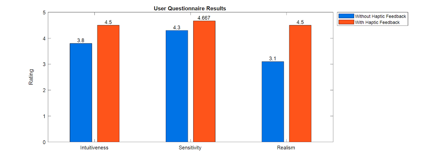
Comparison of steering experience with and without haptic feedback
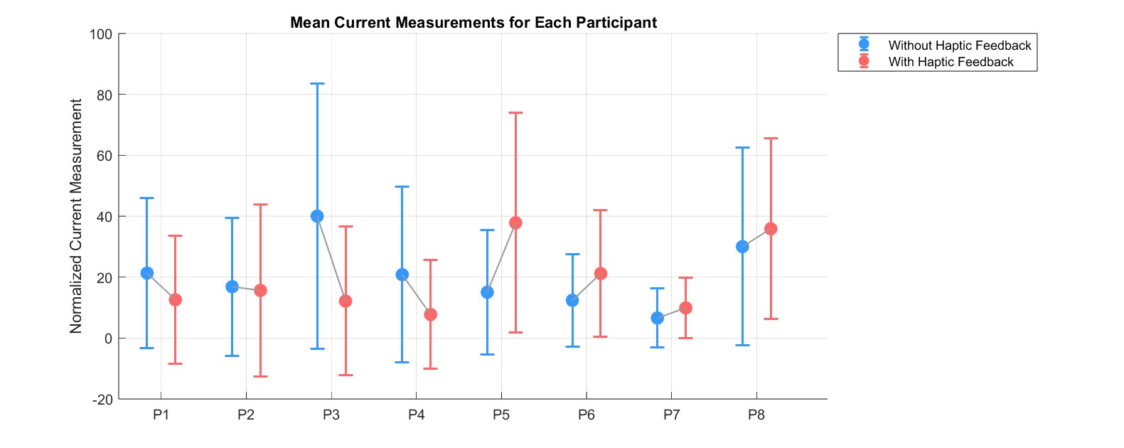
Comparison of motor current levels with and without haptic feedback
The mean value of normalized current experienced during a trial was slightly lower with haptic feedback than without, however, a paired t-test showed that the difference was not significant. However, qualitative feedback suggested that the addition of haptic feedback improved the steering process. For example, one user said that �Haptic feedback made me more confident when avoiding [pipe] walls�. Additionally, the user survey results indicate that the addition of haptic feedback to the steering mechanism improved the overall experience of vine robot operation. Compared to the traditional way of steering the vine robot through a GUI, the sensitivity, intuitiveness, and realism of steering the robot through teleoperation with or without haptic feedback provided for an improved experience.
Future Work
Although the haptic feedback device we created is a successful first prototype, there are multiple areas which we are hoping to improve upon as this project will likely continue within CHARM Lab�s vine robot research group. The key areas of improvement are listed below:
- Conduct user testing with and without haptic feedback where the user�s visual feedback is only the camera view at the tip of the robot, instead of being able to see the entire transparent pipe structure
- Add a motor to provide force feedback in the second degree of freedom as there are some situations during turning when this could be helpful
- Switch to a wireless communication method between the teleoperation fixture and steering mechanism
- Continue refining wall detection and force feedback directionality algorithms
- Switch steering mechanism motors to incorporate direct position sensing
- Improve heat dissipation of teleoperation fixture and steering mechanism motors
- Reduce number of power supplies required (currently need 12V, 9V, 5V separate)
Acknowledgments
We would like to acknowledge CHARM Lab for letting us borrow supplies to complete this project, as well as the teaching staff for providing constructive feedback and all of the users who tested our demo which led us to discover meaningful results.
Files
Processing Code: Attach:Processingcode.txt
Base Code: Attach:BaseCode.txt
Tip Code: Attach:TipCode.txt
References
[1] D. A. Haggerty, N. D. Naclerio and E. W. Hawkes, "Hybrid Vine Robot With Internal Steering-Reeling Mechanism Enhances System-Level Capabilities," in IEEE Robotics and Automation Letters, vol. 6, no. 3, pp. 5437-5444, July 2021, doi: 10.1109/LRA.2021.3072858.
[2] A. Giri, C. Girerd, J. Cervera-Torralba, M. T. Tolley, and T. K. Morimoto, �InchIGRAB: An Inchworm-Inspired Guided Retraction and Bending Device for Vine Robots During Colonoscopy,� IEEE/ASME Trans. Mechatronics, vol. PP, pp. 1�12, Jan. 2025, doi: 10.1109/TMECH.2025.3535876.
[3] M. M. Coad et al., "Vine Robots," in IEEE Robotics & Automation Magazine, vol. 27, no. 3, pp. 120-132, Sept. 2020, doi: 10.1109/MRA.2019.2947538.
[4] P. A. der Maur, B. Djambazi, Y. Haberth�r, P. H�rmann, A. K�bler, M. Lustenberger, S. Sigrist, O. Vigen, J. F�rster, F. Achermann, E. Hampp, R. K. Katzschmann, and R. Siegwart, �RoBoa: Construction and Evaluation of a Steerable Vine Robot for Search and Rescue Applications,� in Proc. 2021 IEEE 4th Int. Conf. on Soft Robotics (RoboSoft), Apr. 2021, pp. 15�20. doi: 10.1109/RoboSoft51838.2021.9479192.
[5] L. H. Blumenschein, M. M. Coad, D. A. Haggerty, A. M. Okamura, and E. W. Hawkes, "Design, Modeling, Control, and Application of Everting Vine Robots," Frontiers in Robotics and AI, vol. 7, Nov. 2020, Art. no. 548266, doi: 10.3389/frobt.2020.548266.
[6] M. J. Jensen, A. M. Tolbert, J. R. Wagner, F. S. Switzer and J. W. Finn, "A Customizable Automotive Steering System With a Haptic Feedback Control Strategy for Obstacle Avoidance Notification," in IEEE Transactions on Vehicular Technology, vol. 60, no. 9, pp. 4208-4216, Nov. 2011, doi: 10.1109/TVT.2011.2172472.
[7] T. Maeda, T. Yoshimura, J. Yamamoto, H. Sakai and K. Minamizawa, "Design and Validation of Pseudo-Force Haptic Device for Actual Walking," 2024 IEEE Haptics Symposium (HAPTICS), Long Beach, CA, USA, 2024, pp. 104-110, doi: 10.1109/HAPTICS59260.2024.10520860.
Appendix: Project Checkpoints
Checkpoint 1
Main Goal: Design and Build Teleoperation Fixture
Our main goal for this checkpoint was to design and build the fixture and user handle that will be used to teleoperate the vine robot tip and deliver force feedback (Figure 1). Our design process, success and challenges in meeting this goal are described below.

Figure 1: Schematic of the user fixture setup.
From our initial proposal we have made one major important change to the design of the teleoperation fixture: From anecdotes of operating the vine robot, motor 2 in Figure 1 is often the motor that is at high risk of experiencing excess current (Figure 1). Since motor 1 has low risk of experiencing overcurrent, we decided that it would not be necessary to incorporate force feedback for this motor�s 1 DOF. Our user handle will still teleoperate this degree of freedom on the vine robot, but without force feedback. This DOF will be incorporated into our fixture with a rotational shaft on a bearing and a potentiometer to send position commands to the corresponding servo motor on the vine robot.
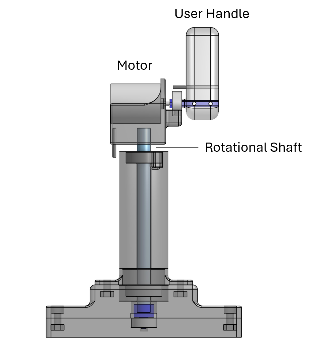
Figure 2: User fixture and handle CAD
We implemented this design change in CAD, 3D-printed, and assembled our fixture (Figure 2, 3), however the 3D-printed motor shaft adapter connecting the motor to the user handle failed due to shearing. We tried reinforcing the 3D printed part with a small metal shaft, however since the part is very thin, we still experienced failure. For our next checkpoint we will remanufacture this component to improve its strength either by changing the 3D print direction or changing the material to metal or a composite.
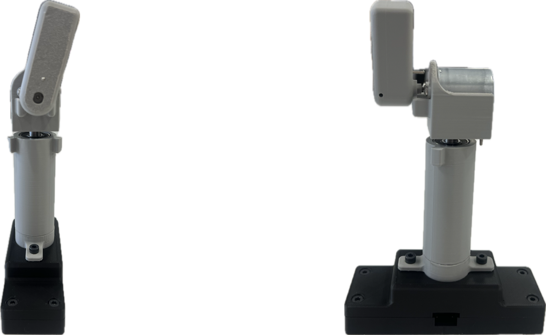
Figure 3: Front and side view of assembled fixture
Additional Progress: Electronics Design and Code
In addition to our fixture design, we began working on our Arduino code and microcontroller circuitry. For the vine robot tip microcontroller, we have completed code that reads motor current from a current sensor and sends this signal to our fixture controller for which we have also completed code that takes in the current signal and calculates the torque to send to the fixture motor. The code for the fixture microprocessor also reads in signals from our two fixture potentiometers in order to send position commands to the vine robot servo motor.
Our next step is to test the code and circuits of these two systems independently, then test the communication of these two systems before soldering our circuits (Figure 4).
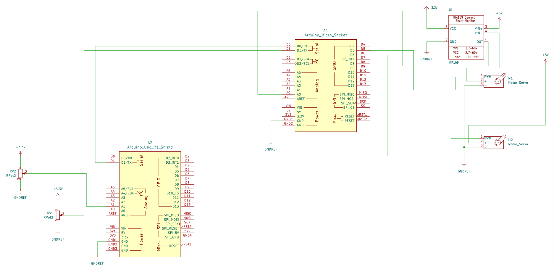
Figure 4: Circuit Schematic
Checkpoint 2
Main Goal: Electronics and Code
Our main goal for this checkpoint was to complete our electrical setup (Figure 1) and controller code, including communications between our user fixture controller (Arduino) and the vine robot controller (ESP 32) as summarized below.
1) Arduino reads in angle values from the potentiometers on user fixture shafts, sends to ESP and commands vine robot servo motors
2) ESP32 reads in servo motor current values from the current sensor, sends to Arduino and commands DC motor to produce torque as force feedback
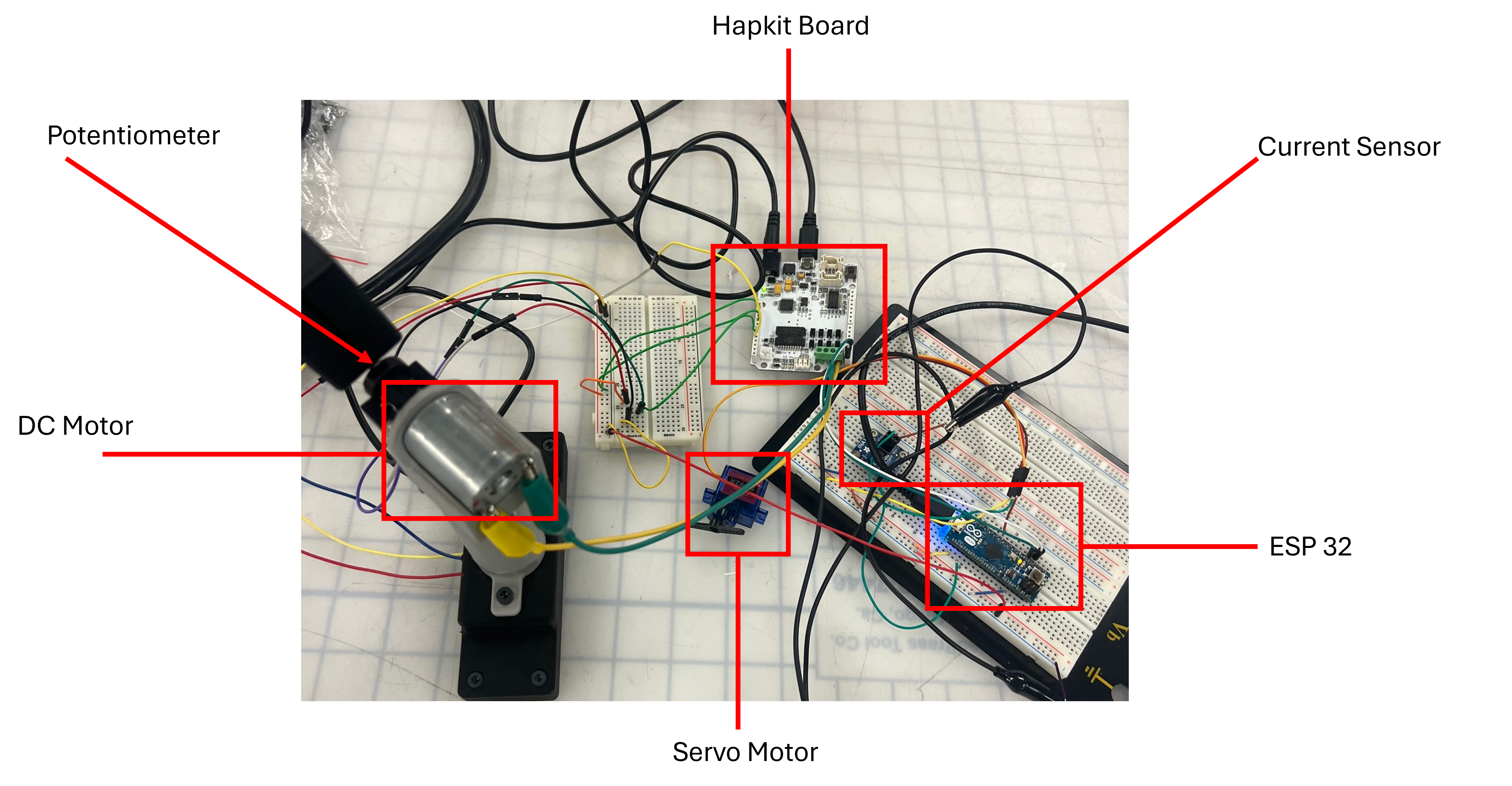
Figure 1: Electronics setup.
We have additionally built a housing for the vine robot containing the ESP32, current sensor, servo motors, and our protoboarded circuit (Figure 2).
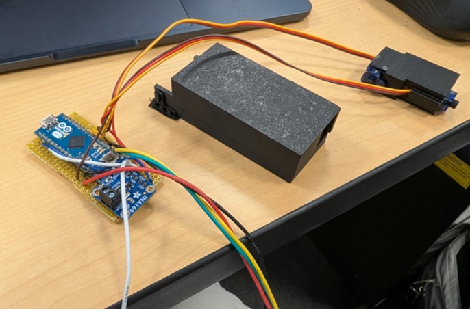
Figure 2: Proto board and housing, servo motors and housing.
An issue we encountered this week was our DC motor making a beeping sound when running. We were able to correct this by adjusting the PWM frequency.
With our fixture built and our mechatronics components functioning and communicating the next step for us is to finetune the force feedback output at the user handle. Currently, with the Hapkit DC motor we are able to perceive the force feedback when steering the servo motors, however, our feeling was that the feedback is not strong enough to discourage a user from continuing to steer in a way that will overcurrent the motors. To remedy this, we have discussed adjusting the handle form factor to maximize the force feedback, acquiring a more powerful direct drive motor, and adding a transmission by adapting our Hapkit capstan.
Currently, our hope is to acquire a new motor that can provide more force. For this we will need to 3D-print a new motor housing for our user fixture. If we cannot achieve the desired level of force with a new motor, we add a transmission by adapting our Hapkit capstan to couple with our current fixture.