

2025-Group 12
Haptic Doodle Jump
Project team member(s): Rosalie Massein, Jinho So, Katelyn King, Shalika Neelaveni
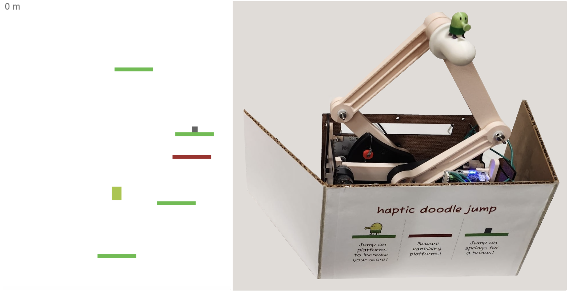
Caption: Haptic Doodle Jump virtual and physical interface.
Haptic Doodle Jump is a fun spin on the iOS game, Doodle Jump. Through our graphics interface, the Doodler jumps from platform to platform to try and get as high up as possible in the game. Our game incorporates a pantograph design to control the horizontal motion of the Doodler who traverses through normal, brittle, and springy platforms that exhibit different impulse parameters as haptic feedback in the vertical direction. We combined core concepts through analysis of pantograph kinematics, implementation of virtual walls, and simulation of projectile motion within this game. Overall, we received positive results from our user study during the open house in terms of our noticeability, realism, stability, and fun, with only a slightly lower score in our stability. We hope to improve the game by re-tuning some stiffness parameters to increase stability, decreasing the map difficulty, and adding more complexity through other game features.
On this page... (hide)
Introduction
Our project is inspired by the classic iOS game, Doodle Jump, in which the user moves upward by jumping across various platforms to achieve the highest vertical distance. We developed a haptic version of the game that integrates force feedback based on the type of platform the character, referred to as “the Doodler,” interacts with. A two-degree-of-freedom (2-DoF) pantograph was built to allow users to command movements in the horizontal direction and simultaneously receive haptic feedback in the vertical direction. The objective of this work was to enhance user interaction by incorporating realistic haptic responses, resulting in a more immersive, engaging, and fun experience!
Background
Haptic feedback systems simulate touch and force to enhance user interaction in virtual environments. Among various designs, the pantograph mechanism is a well-studied 2-DOF haptic device known for its mechanical simplicity and precision. Campion et al. (2005) introduced the Pantograph Mk-II, which became a benchmark for planar haptic devices due to its transparency and control fidelity [1].
Force feedback rendering has also evolved through work by Colgate and Brown (1994), who established stability conditions for passive haptic systems [2], and Hayward and MacLean (2007), who explored the importance of combining tactile and kinesthetic cues [3]. Recent efforts have brought haptic feedback into gaming environments. Devices like the Novint Falcon and PHANToM Omni have been used in commercial and educational applications to translate game mechanics into physical sensations. These devices illustrate the growing potential of haptics to improve immersion and motor learning in interactive systems.
Minamizawa et al. (2007) introduced the Gravity Grabber, a wearable haptic display that generates vertical forces on the user's fingertips to simulate sensations of weight and mass in virtual environments [4]. This project is especially relevant to our work, as it demonstrates how vertical kinesthetic feedback can transform abstract game mechanics into physically intuitive experiences. By linking virtual cues to real-world vertical force output, it laid the foundation for immersive interactions that mirror our goal: rendering platform-dependent vertical forces in a jumping game. Our project builds on this foundation by using a pantograph to control a Doodle Jump-inspired game. Unlike standard controllers, it renders dynamic vertical forces that reflect different platform types (e.g., springy, brittle), enhancing immersion and physical realism during gameplay.
Methods
The three primary subsystems for this project are the pantograph/hardware, Hapkit code, and game graphics.
Hardware Design and Implementation
We constructed a pantograph based on a five bar linkage; uniquely, our configuration has four links with the remaining link having zero length (Fig. 1), which increases the horizontal range of motion. This is important because we used the horizontal DOF for position control, translating user movements to horizontal movement of the Doodler in the game. We chose a 2 DOF device because, in addition to position control in the horizontal plane, we sought to provide haptic feedback in the vertical plane to simulate collisions between the Doodler and the virtual platforms.
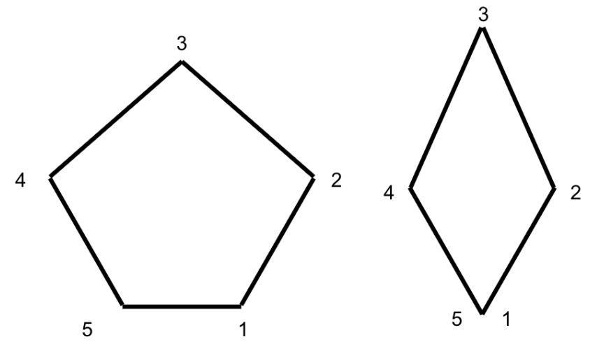
Figure 1: Standard pantograph geometry (left), modified pantograph geometry (right)
To construct the pantograph, we used a Bambu printer with PLA filament to 3D print most of the components, including the pantograph links, sector pulleys, washers, bearings, shaft hubs, and mounts for the links and electronics. For the housing, we laser cut walls from 1/8” Duron and fastened them together with nuts and screws. To attach the pantograph links, we used 2mm diameter cylindrical metal shafts and compatible set screw shaft collars. We mounted the 3D printed shaft hubs to the sector pulleys by tapping the holes in the shaft hubs and attaching the hubs to the sectors with bolts. The CAD files of the full assembly are attached at the end of this report. Figure 2 below shows the overall dimensions of the device as well as the CAD assembly.
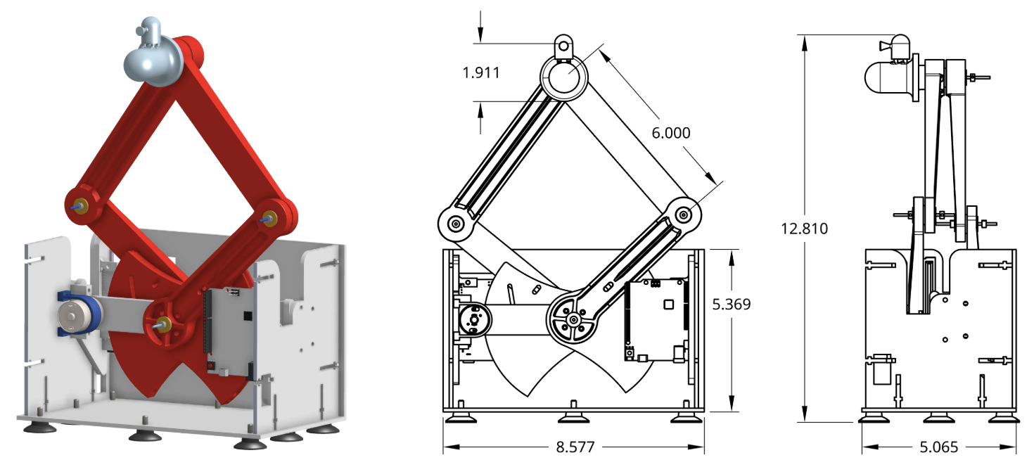
Figure 2: Pantograph assembly (left), dimensioned drawing (right)
The pantograph is actuated by a pair of motors that operate at joints 1 and 5 in the diagram from Figure 1 via capstan drive. To eliminate the need for communication between the Hapkit boards, we wired both motors to the right Hapkit board and used jumper wires to connect the MR sensor output from the left board to the right board (Fig. 3).
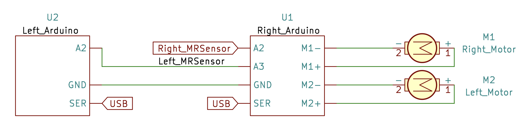
Figure 3: Circuit schematic showing connections between pairs of motors and Hapkits
Hapkit Firmware
The right Hapkit was programmed to control the motors and read the magnetic sensors on each board. All data processing was performed on the right Hapkit while the left Hapkit functioned as a sensor only. Both haptics were connected via USB to a computer which rendered the game graphics. The two main functions of communication between the Hapkit and game were (1) position control and (2) force feedback.
Position Control The horizontal position of the pantograph handle was used to control the horizontal position of the Doodler in the game. Data processing occurred on the Hapkit side, whereby the right board read the position of each magnetic sensor, computed the pantograph kinematics, and sent the horizontal position of the handle to the game via serial communication at 115200 baud. The game updates the Doodler position when it receives a new value. A block diagram illustrating communication between the Hapkit and the game is shown in Figure 5 below.
We determined kinematic equations for the pantograph based on prior research [1]. This model yielded equations for the position of the handle as a function of the angle of the pantograph arms (Fig. 4). We measured these angles via the magnetic sensors used to track motor position. Since the sensors tended to be noisy, we computed the change in angular position at each loop and incremented the angular position accordingly. This allowed us to reject noisy measurements and achieve smoother position control.
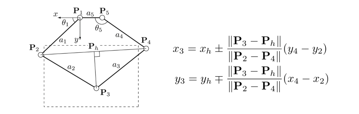
Figure 4: Pantograph kinematics [1]
Force Feedback – Virtual Walls We provided haptic feedback to the user when they hit the virtual floor/ceiling and/or collided with a platform in the game. We chose to implement a virtual floor/ceiling to maximize the horizontal range of the pantograph. Below the virtual floor, the pantograph has limited horizontal range of motion due to interference between the arms and housing; above the virtual ceiling, the pantograph kinematics restrict the horizontal range of motion. In addition, the virtual ceiling counteracts the tendency of users to try to move the Doodler up by raising the pantograph handle higher. When the user enters a virtual wall, the force applied by the pantograph is:
f_wall = k_wall*(y_wall-y_handle)
where y_wall is the vertical position of the floor/ceiling, y_handle is the vertical position of the pantograph handle, and k_wall is the stiffness of the virtual wall. This calculation occurred entirely onboard the Hapkit and required no communication with the game.
Force Feedback – Impulse To simulate collisions with virtual platforms, we applied an impulse of variable magnitude and predetermined duration according to the impact velocity and platform type. Scaling the applied force in this way required communication between the Hapkit and game. A block diagram illustrating communication between the Hapkit and game is shown below.
The game simulated the projectile motion of the Doodler. We ignore air resistance and model the Doodler as a projectile in free-fall such that the vertical velocity of the Doodler is given by:
vy=vyf - gt
where g is gravitational acceleration, vy,f is the vertical velocity of the Doodler when it leaves a platform, and t is the time since the last collision. We assign the vertical velocity based on the platform type as shown in Table 1. Since the springy platform launches the Doodler much higher than the other platforms, we assigned it a higher final velocity. Each time the game code loops, it updates the velocity according to the equation above. Based on these dynamics, we set the force that the pantograph should apply when the Doodler collides with a platform. Assuming a near-instantaneous collision, we derived the impulse force by applying conservation of momentum (𝜌) as follows:
Δ𝜌 = FΔt = m(vyf - vy0) = m/Δt*Δv
where m is the mass of the Doodler (for simplicity, we set m = 1 kg), Δt is the duration of the collision, and Δv is the change in the vertical velocity of the Doodler due to the collision. We assigned the duration of the collision according to the platform type. The brittle platform has the shortest collision because it breaks on impact. The springy platform has the longest collision since a spring realistically takes time to change length. When a collision occurs, the game sends the platform type and pre-collision velocity of the Doodler to the Hapkit via serial. The Hapkit then computes the impulse magnitude via the equation above and actuates the pantograph.
Table 1. Impulse parameters designed for each type of platform
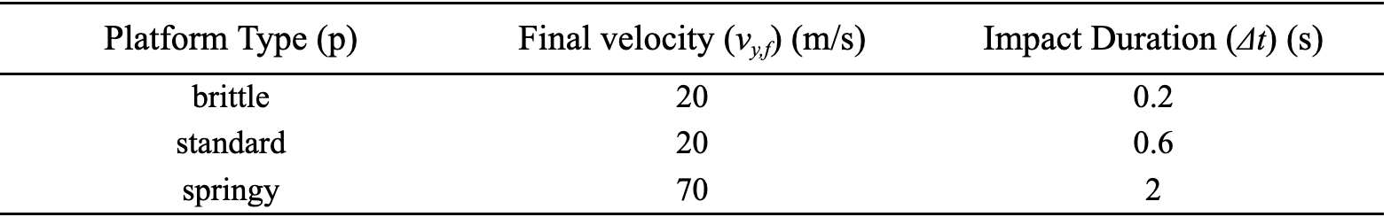
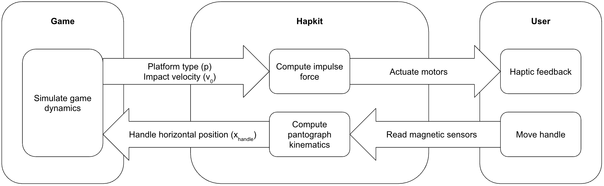
Figure 5. Feedback loop between user, Hapkit, and game
Game Graphics
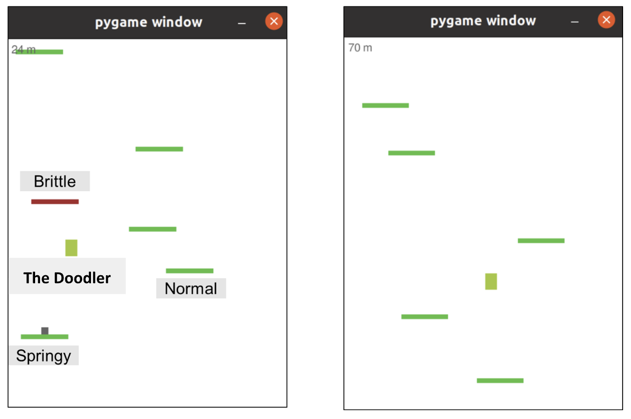
Figure 6. Graphics demonstrating interface with the Doodler and normal, brittle, and springy platforms.
The main game loop of the program consists of three components [5]: a render loop, an event loop, and an update loop.
The render loop is responsible for rendering the user interface (UI) in each cycle. Since the game includes three types of platforms, they are visually distinguished using different colors and an additional box to indicate a springy platform. The player character, Doodle, is rendered in light green. The platforms are randomly generated during gameplay.
The event loop handles collisions between Doodle and the platforms. When a collision is detected, appropriate events are triggered, such as applying an additional initial velocity when interacting with a spring platform or removing the platform after the player jumps.
The update loop updates the position of Doodle in each cycle. Physical dynamics such as gravity and lateral acceleration are implemented in this loop. We also integrated our serial communication module into this loop, enabling the player to control Doodle using a custom input device equipped with haptic feedback. The game program receives real-time x-position data from an Arduino device.
To map the handle position to game controls, the handle input is divided into three zones: the left zone and right zone provide acceleration in the corresponding direction, while the center zone enables a stationary jump. This stationary jump feature was introduced to improve controllability, allowing the player to strategically plan their next move when stepping onto the next platform.
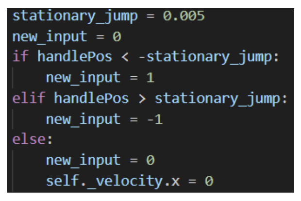
Figure 7. Snippet of code to map handle position.
Demonstration / Application
Figure 8 below demonstrates the graphics interface and hardware we built.
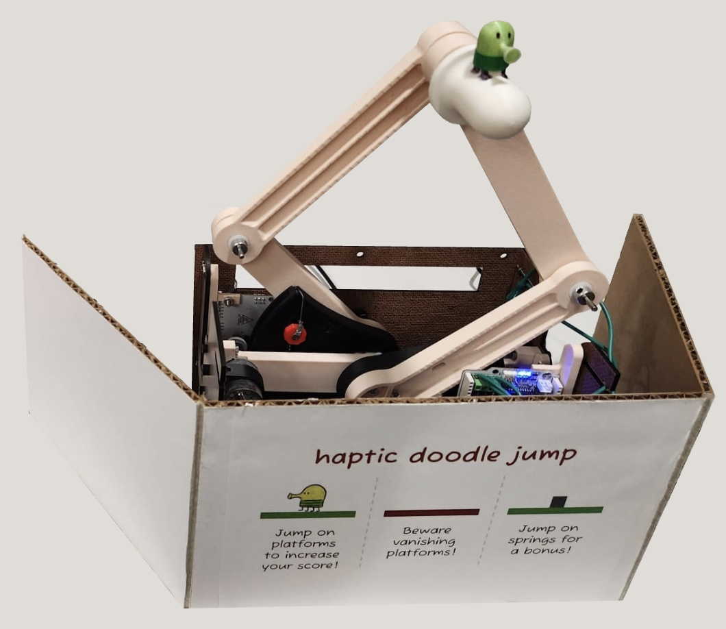
Figure 8. Game graphics (left) and hardware interface (right)
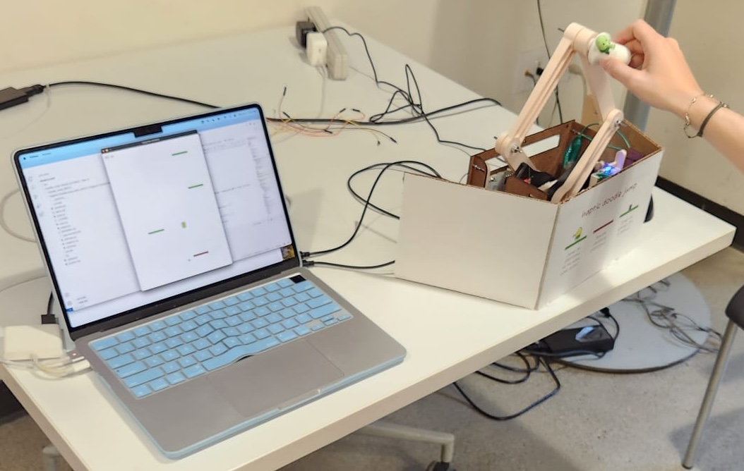
Figure 9. Demo setup during open house showing user interaction
Results
We found that the best way to evaluate our system was through qualitative user responses from the open house (Fig. 9), where the results are demonstrated in Figure 10 below. Overall, we noticed a very positive response from the users in regards to the noticeability, realism, stability, and entertainment of our game.
Firstly, a strong majority of our responses suggested a high level of noticeability with 74.6% of participants rating it a 5/5. There were some 3 and 4 ratings, which may have been due to a desire of some users wanting to see a higher stiffness value in the platforms to feel a more intense “bounce”.
In terms of realism, we once again received a majority of 5 ratings. However, some of the 3 and 4 ratings may have been due to the fact that for some “maps” generated by the program, there seemed to be only one strategic path for the user. Therefore, it may have been better to exclusively generate “maps” that would allow for multiple paths.
The stability/noise-free section of the survey received the most varied responses. Just over 50% of participants gave our system a full score, while the rest of the responses ranged between 2 to 4 out of 5. While setting up our system at the start of the open house, we noticed that we had a lot of noise coming from the virtual walls that were set to limit the user’s motion in the vertical direction. We made sure to tune our stiffnesses for these walls prior to the open house, however it seemed to have some issues during demo day. Therefore, this primarily contributed to the lower stability felt by some users and in the future could be corrected with a simple re-tuning of the stiffnesses.
Finally, we confirmed that the users had fun playing our game, especially as we noticed many participants returning to play again and beat their previous high score!

Figure 10. Results from user study of ranking between 1 to 5: (a) haptic rendering noticeability where 1 is not noticeable and 5 is very noticeable, (b) realism where 1 is not realistic and 5 is very realistic, (c) stability where 1 is not very stable and 5 is no noise in feedback, and (d) fun in game where 1 is not fun and 5 is really fun. Twenty-seven users were surveyed.
Future Work
In the future, there are a couple of different things we could implement to enhance our game further. As mentioned in the Results section, re-tuning our stiffnesses for the virtual walls immediately prior to the open house could have helped improve the overall stability of our system for all our players. Another future work would be to generate slightly easier “maps” that would allow for more than one path by the user, as observing users revealed the game to be a bit too challenging. Furthermore, there are other editions of this game with more complex features (i.e. moving platforms) that could be included in our version to make it more challenging. In terms of testing, we could also conduct further studies to determine what combinations of final velocities and impulse durations achieved the most desirable and realistic haptic feedback among users for the different platforms.
Acknowledgments
We would like to thank Ryan Nguyen for being our primary point of contact on the teaching team for our final project. We would also like to thank Teo Ren and Professor Allison Okamura for the amazing lectures and constant support during our time in the class.
Files
Pantograph CAD Assembly: Attach:FullAssembly.zip
Bill of Materials: Attach:BoM.xlsx
Game Code: Attach:Pygame-DoodleJump-main.zip
Hapkit Code: Attach:DoodleJump.zip
Virtual Floor/Ceiling Demo: Attach:wall.mov
Jumping/Graphics Demo: Attach:jumping.mov
References
[1] Campion, G. et al. (2005). The Pantograph Mk-II: A Haptic Instrument. IROS.
[2] Colgate, J. & Brown, J. (1994). Z-width of a haptic display. ICRA.
[3] Hayward, V. & MacLean, K. (2007). Do it yourself haptics: Part I. IEEE R&A Magazine.
[4] Minamizawa, K., Fukamachi, S., Kajimoto, H., Kawakami, N., & Tachi, S. (2007). Gravity Grabber: Wearable haptic display to present virtual mass sensation.
Appendix: Project Checkpoints
Checkpoint 1
Goal 1: Complete the CAD model of the vertically-oriented pantograph suited for user input and haptic feedback
We modified an existing pantograph design (https://charm.stanford.edu/ME327/2023-Group1) to fit our application. The existing model is oriented in the XY plane, so we reoriented it to operate in the XZ plane by adding mounts to support the motors and moving the rubber feet to the base of the housing.
Goal 2: Begin 3D printing initial structural components
We began prototyping the design by printing the pantograph links and mounts for the sectors and Hapkit boards. We planned to use the sectors we already had in our Hapkits, but upon assembly realized that modified sectors are needed for this pantograph design. Therefore, we will continue to use the capstan-based drive mechanism that was previously used within the Hapkits, but with two motors to create the 2 dof system. Also, we planned to source the hardware required for this build (i.e., D shafts, shaft collars, shaft hubs, bushings) from AMPS, but discovered that they did not have all the components in stock. We plan to design the assembly to accommodate the components that we have on hand and purchase anything that is required. For the time being, we bolted the pantograph links together to get a sense of the scale and workspace of the device. For the housing, we laser cut Duron (⅛” thick) and assembled the pieces with M3 nuts and screws. We do not plan to make further design modifications as it turned out nicely.
Left: Pantograph CAD model, Right: Progress toward physical prototype
Goal 3: Create a basic mock-up of the Doodle Jump-inspired game interface (a character controlled horizontally with placeholder platforms)
We built a simple Doodle Jump–style game in Pygame. Each platform’s stiffness is indicated by its color, and the character is currently controlled with the keyboard arrow keys. On the hardware side, an Arduino streams position data; if the incoming position is negative the character will move left, and if it is positive the character will move right. Communication between the game and the Arduino will use a serial link. Going forward, the rendering program will tell the Arduino which platform the character is landing on. The Arduino will then translate that platform’s stiffness into the appropriate motor torque, allowing the player to feel realistic haptic feedback.

Example of the graphical interface developed.
Goal 4: Set up Arduino communication to ensure basic positional data from the pantograph can be read by the computer
In order to set up Arduino communication, we elaborated a sketch of Arduino code that begins to integrate the dynamics of our pantograph. We uploaded this code to the Hapkit board and used the Serial Monitor to verify that the magnetic rotary sensors are providing real-time input. Specifically, we confirmed that the Arduino receives angle data from the sensors and successfully transmits key variables such as motor angles through the serial interface. Although the pantograph is not yet physically connected to the Hapkit and we therefore cannot track the end-effector position (P3x, P3y), we have structured the Arduino code to support the future transmission of this information, with a focus on tracking P3x for horizontal avatar control. The next step will be to calibrate both Hapkit sensors to ensure accurate angle readings and consistent mapping between the physical hardware and the virtual environment, which will be essential for delivering precise haptic feedback and position tracking during gameplay.
Checkpoint 2
Goal 1: Finish 3D printing and assemble the full pantograph mechanism We were able to fully complete our pantograph. From last week, we needed to print the modified sectors, motor mounts, and shaft hubs. All these parts were 3D printed and incorporated into the assembly. The main modification we made to our setup was to include 2 mm shafts and shaft collars rather than the 4 mm shaft and shaft collars that were used in the original assembly, as this is what we were available on hand. This allowed us to successfully incorporate the motors and capstan, allowing us to have a fully complete pantograph system. No modifications were made to the laser cut housing.

Goal 2: Define the dynamic behavior of each platform type (brittle, standard, springy, trampoline) and how force feedback will differ for each case
We decided at this point to render impulse feedback that will be more important for the springy platform and lower for standard platform. For the brittle platform we chose to render the exact same force as the standard platform but this platform will then disappear from the game interface after the character bounced once on it. The value of the impulse force will be tuned to have the more realistic feedback.
Goal 3:Finalize the Game Interface with Functional Platform Types
The game features three platform types: normal, brittle, and spring. Both normal and brittle platforms give the character an initial upward speed upon contact. However, the brittle platform disappears after the character steps on it. The spring platform provides a much higher initial speed compared to the others.
Goal 4:Implement Bidirectional Communication Between Arduino and the Game for Real-Time Control and Haptic Rendering
We used serial communication to exchange data between the graphical rendering program and the Arduino-based game controller, which provides haptic feedback. The program sends information about the type of platform the character is colliding with, and the Arduino sends the controller’s position data to control the character's movement in the game.
Goal 5: Outline the control architecture for vertical haptic rendering
After unwrapping the left and right encoder and converted it to joint angles using :
  theta1 = radians(m_left * updatedL + b_left);
  theta5 = radians(m_right * updatedR + b_right);
We aim to calculate the position of the end effector P3 considering the geometry of our pantograph:
From this we can deduce the position of the joints P2 and P4 with :
  P2x = a1 * cos(theta1);
  P2y = a1 * sin(theta1);
  P4x = a4 * cos(theta5) - a5;
  P4y = a4 * sin(theta5);
In order to have the position of P3, we use its projection onto the line linking the joints P2 and P4 – we call this point Ph. With that we can have P3x : x3 and P3 : y3 the coordinates of P3.
The x-position of the end effector (P3x) will be sent to the Python code which will use it to update the character position on the game interface.
Goal 6: Code and test vertical haptic feedback triggered by avatar-platform collisions
We successfully integrated the Arduino code to the pantograph by using stamps to link the two board and collect the data from both sensors. We connected them via A3 for Left sensor and A2 for Right sensor:

We now need to calibrate the two sensors so that we can do further work upon the Arduino code and test the feedback rendering and tune parameters for a realistic game.
