

2025-Group 17

Haptic Brick Breaker
Project team member(s): Saimai Lau, Yiyang Wang, Zhangying Xu, Qianhe Ye
HAPTIC BRICK BREAKER is a 2-DOF interactive brick-breaking game designed to enhance traditional gameplay with physical immersion and educational value. Motivated by the limitations of classic 1-DOF paddle control, we introduced both horizontal motion and rotation to give players better control over ball dynamics. The system integrates mechatronic design, real-time haptic rendering, and force-feedback using an 8-bar linkage and 2 motors. Key effects like Spring Trap simulate physical resistance and collisions, enriching the tactile experience. The game attracted strong user engagement at demo events, where real-time leaderboards, dynamic feedback, and competitive play encouraged participation and sparked interest in the underlying engineering principles.

On this page... (hide)
Introduction
Our project was inspired by classic brick-breaking games that used a horizontally movable paddle to control the ball's trajectory. While these games were simple and fun, their one-degree-of-freedom (1-DOF) control scheme limited the player's ability to influence the ball’s motion in a nuanced way. To enhance both gameplay and the educational value of the system, we introduced an additional rotational degree of freedom—allowing the paddle to rotate ±45 degrees about its own axis. This extra control dimension enabled players to physically affect the ball’s bounce angle with greater precision, creating a more dynamic and immersive interaction.
From an educational perspective, the project supported learning in key areas of mechatronics, dynamic modeling, and human-computer interaction. It challenged us to integrate mechanical design, control systems, and real-time haptic rendering into a cohesive and responsive platform. By simulating realistic collision dynamics between the paddle and the ball—and incorporating haptic feedback through both translational forces and rotational torques—the system provided an engaging way to explore force-feedback control and interactive system design.
To realize this concept, we designed a haptic device capable of both horizontal and rotational motion. Horizontal motion was achieved using an 8-bar linkage driven by a single motor, while paddle rotation was controlled using two motors and a capstan drive. This configuration allowed us to render complex haptic effects such as vibration and resistance.
In summary, our haptic brick-breaking game combined fun with educational value by enabling physical interaction through a 2-DOF force-feedback interface. It not only enriched the gameplay experience but also served as a hands-on platform for applying concepts in mechanical design, system dynamics, and haptic feedback.
Background
Our project builds on a range of prior research that explores innovative approaches to haptic device design and feedback strategies. Kim et al. (2022) developed a compact 2-DOF haptic impact actuator capable of generating directional forces in the X and Y directions using an electromagnetic array. Unlike conventional 1-DOF vibration actuators, their system enables precise control over both the direction and intensity of feedback, making it ideal for portable and handheld applications. Gianni (2011) introduced the Pantograph Mk-II, a 2-DOF haptic device based on a five-bar planar linkage, which integrates brushless DC motors and force sensors to deliver high-fidelity, real-time force feedback at frequencies up to 400 Hz. Its open architecture also supports a wide range of research applications, making it a valuable reference for our linkage-based design. Park et al. (2009, 2010) designed and later improved a 2-DOF haptic interface for the Brickout game, incorporating both paddle translation and rotation. Their system provided real-time tactile effects such as friction, bounce, blocking, and detents—particularly during rotation—greatly enhancing the sense of physical realism and player immersion. These contributions directly inform our own system, particularly in how we integrate real-time control and layered tactile feedback into a dual-DOF setup. Additionally, a related work on a single-DOF haptic device based on the Peaucellier-Lipkin mechanism presents a design that achieves perfect straight-line motion with a larger workspace and greater force output than other 1-DOF systems. By optimizing link lengths, the authors minimized the mechanism’s footprint while maintaining performance, and characterized its behavior through bandwidth and apparent inertia measurements. Together, these studies guide our approach by demonstrating the value of precise force rendering, mechanically optimized linkages, and dynamic tactile effects in creating responsive and immersive haptic interactions.
Methods
Hardware Design and Implementation
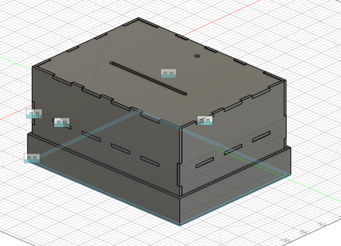
Our device primarily has 2 mechanical systems - an eight-bat linkage driven by capstan drive and a pulley system modified from a capstan drive. Each of them relies on a Maxon 118743 DC motor with a Maxon HEDS 5540 encoder to interact with the software. However, since each Hapkit board only has 2 interrupt channels while each encoder and Serial communication port needs at least one to work well, thus we used 2 Hapkit boards. One Hapkit board reads from the encoder to compute and send position information to Processing on a laptop computer while the other controls the motors based on Serial data sent from the laptop. All these were placed inside a transparent acrylic box we made from laser cutting, only the paddle and some wires
Peaucellier-Lipkin Inversor Linkage System
To achieve the linear trajectory at the handle, we applied an eight-bar Peaucellier-Lipkin Inversor linkage system

We 3D printed the linkages with 0.19" thickness and connected them using bearings and shafts for lower friction. The motor with capstan was mounted at the lower circle below the sector to drive the sector and thus the mechanism. We also made a rectangular handle for easier grip of the handle. This is how it looks on the finalized device:

Pulley System
A pulley system was used such that our device can have a rotational degree of freedom.

The main interaction happens between the drum pulley mounted at the bottom of the paddle and the capstan on the motor, the other 2 pulleys mounted outside the bounds of the linear track were there such that the capstan and motor do not need to translate with the drum pulley. The pulleys and capstan are aligned such that the string is parallel on both sides, effectively minimizing unwanted force in the front-back direction (or vertical direction in the above image) that would pull the drum pulley and capstan toward each other.
System Analysis and Control
Peaucellier-Lipkin Inversor Linkage System
Schematic of the linkage system is as follow:


with parameters

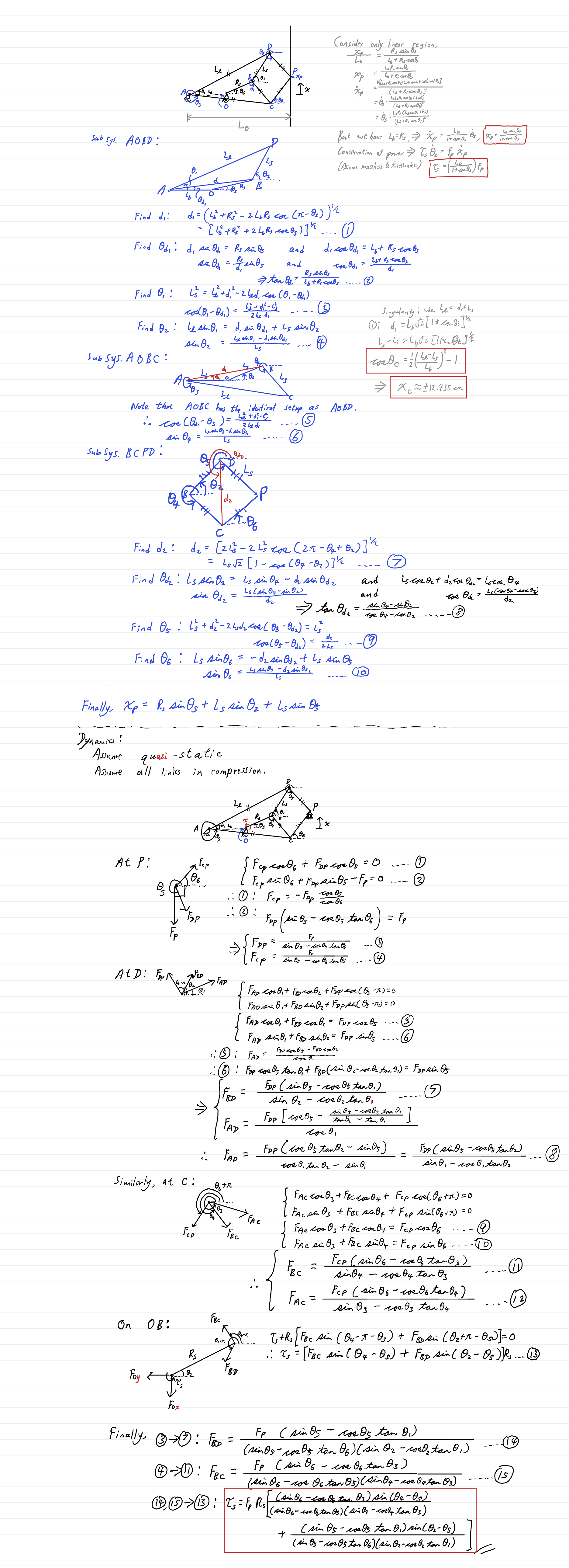
By the derivation in the appendix, all the angles and internal forces can be obtained by evaluating


Then, the current paddle position and the desired torque output at link OB are

However, by bounding the domain to only the linear region and by conservation of power, the position and torque can also be computed as

Validation of the simplified expressions are in Checkpoint 2 of the appendix.
Finally, relating all these to the input/output at the motor,


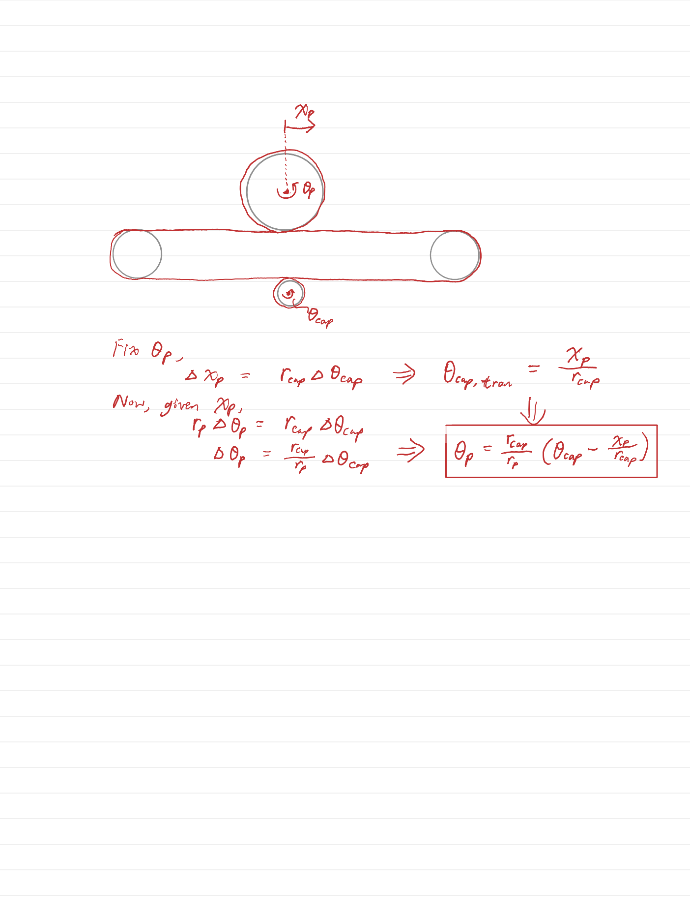
Pulley System
Schematic of the linkage system is as follow:

with parameters

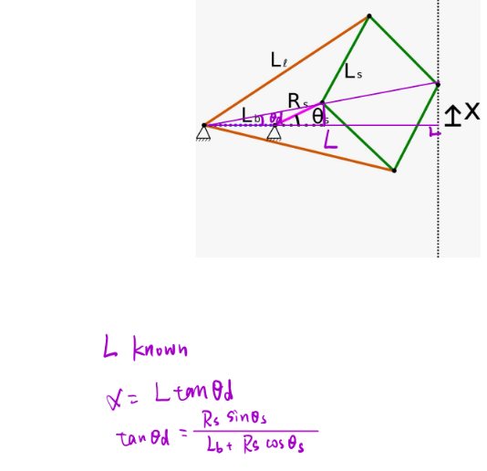
Again, by derivation in the appendix, the angle of the paddle is ideally
Nevertheless, since xp is obtained from the linkage system and we didn't have extremely precise measurements of all the lengths and radii, the term (xp/R_p) was empirically fitted by a first order linear regression. That means, the actual equation used in our pulley control was
Aside from that, force output for the pulley system was simply
Rendering In Virtual Environment
When the ball collides with any of the bricks or the walls, the sign of its velocity in x or y direction would simply be flipped. The difficult and more haptic relevant part is the ball's interaction with the paddle.
Upon impact of the ball with the paddle, a proxy ball would be created right outside the corresponding side of the rectangle and saved in the paddle's body frame such that the proxy ball could move with the paddle while it is still "in contact" with the paddle. The status of whether the ball is "in contact" depends on the hidden true ball that keeps going into the paddle. When the true ball is inside the paddle, it feels a spring force with kb=600 N/m. That said, instead of do it like a virtual wall where the force is proportional to the displacement from the wall, we used the displacement of the true ball from the proxy ball,

This way, the force changes direction as the proxy ball is moved by the paddle. At first we wanted to apply the same force and torque to the user as kinesthetic feedback, but the horizontal force along the axis of the physical paddle track is usually not large enough to tell it apart from the friction in our first prototype of the mechanical device. Therefore we switched to apply a controlled vibration using the motor in the pulley system as well as a disk vibromotor on the paddle. Additionally, we added a toggleable spring effect that pulls the paddle back to horizontal center of the track, with kp=30 N/m and
Lastly, to make the motion appear smoother on the screen, the proxy ball was only restrained in one direction in the paddle frame, it could slide along the side of the paddle as the true ball moves inside the paddle.
Demonstration / Application
In our Haptic Brick Breaker game, the user moves or rotates a physical paddle to control the virtual paddle on the screen and hit the ball. When the paddle strikes the ball, the user feels a vibration through the real paddle. Additionally, when the ball hits a brick, a haptic effect—such as a spring sensation—may be triggered and felt through the paddle during movement.

Our project demonstrates how haptic feedback can enhance user interaction in gaming and training environments. By combining real-time force rendering with physical motion, the system showcases potential for applications in immersive simulations, skill training, and interactive entertainment.
Results
Educational Results
HAPTIC BRICK BREAKER was showcased as an interactive force-feedback game designed to immerse users in tactile experience while challenging them to score as many points as possible. The system combined intuitive physical interaction with haptic effects such as Spring Trap and Impact Jolt, encouraging players to adapt their strategies to unpredictable physical disturbances.
As students and visitors engaged with the game, they quickly became immersed in the competitive atmosphere. A real-time leaderboard displayed the top scores, motivating users to reattempt the game and outscore their peers. The presence of dynamic haptic disturbances created excitement, laughter, and curiosity, with participants often discussing how each effect changed their gameplay.
Observers frequently asked questions about how the force feedback was rendered and how the paddle movements were controlled. Many users returned for multiple rounds to "beat the haptics" and improve their score, which speaks to the effectiveness of the system in blending education, engineering, and fun.

The final leaderboard:

Design Results
The HAPTIC SMASH system features a dual-degree-of-freedom paddle — allowing for both horizontal movement and rotation. The paddle is driven via a Maxon motor with a capstan mechanism and real-time control via Arduino. The haptic effects were programmed in Processing, dynamically triggered based on game state and collisions.
Key haptic effects implemented include:
1.Spring Trap: Increasing resistance as the paddle nears screen edges, mimicking a stretching spring.
2.Impact Jolt: Instant vibration feedback when the ball strikes the paddle, simulating physical collision.
Force Pull, Magnetic Drag, and more are under testing and refinement.
A clean graphical interface with a live score and ranking panel provided immediate feedback, supporting both competition and engagement. The modular codebase and physical system allowed for easy customization of haptic profiles, paving the way for future iterations involving more nuanced tactile experiences and educational applications.
Future Work
System Test
Our Haptic Brick Breaker System can be tested with the following steps :
STEP1.When the user moves or rotates the physical paddle, the virtual paddle on the screen should move synchronously.
STEP2.When the user controls the virtual paddle to hit the ball, the real paddle should vibrate.
STEP3.When the ball hits a brick, the triggered haptic effect (e.g., spring) will be displayed on the screen. The user should feel the corresponding haptic effect when moving the paddle.
Mechanical Design Iteration
While testing our system, we found that the capstan might occasionally slip, and we also felt resistance when moving the paddle. Although we have attempted to redesign and reassemble the 8-bar linkage to improve smoothness, there are still areas that need improvement:
- Redesign the connection between the paddle and the drum to make it easier to control the paddle and to prevent the drum touching the platform.
- Redesign the capstan to prevent the cable from sliding vertically.
- Reinforce the sector from below to prevent wobbling.
Hardware Improvement
The Hapkit board is equipped with only two interrupt pins and one serial port, while our system requires two encoders and two motors. This hardware limitation causes communication delays. When we attempted to add haptic effects that require the real-time position and velocity of the paddle, the delays resulted in unrealistic haptic feedback. Therefore, an alternative board is required for improvement.
Haptic Effect Improvement
Due to the complexity of the 8-bar linkage system, it is difficult to generate precise forces to simulate the effect of the ball hitting the paddle. Therefore, we use vibration to simulate this in our current system. Additionally, we were only able to implemente spring haptic effects because of slipping and delay. After improving the mechanical design, we can attempt to add the following haptic effects:
- Try vibration motor to generate vibration.
- Simulate the force when the ball hits the paddle using the two motors.
- Add more haptic effects such as damping, bumps, and valleys.
Acknowledgments
We would like to express our sincere gratitude to Alison and the CHARM Lab for their support throughout the course, as well as for lending us the motors that were essential to our system development.
We also want to thank our TAs, Teo and Ryan, for their careful guidance and detailed feedback from different perspectives. Teo helped our team select the appropriate cables and provided access to useful components in the lab. Ryan assisted us by acquiring various screw and bearing parts that were critical for completing Checkpoint 1.
Lastly, we greatly appreciate the friendly and helpful PRL TAs, whose support and responsiveness made our fabrication process much more efficient.
Files
CAD files (Fusion 360) can be found here: Attach:SP25Team17Haptic_Brick_Breaker.zip
The code: https://github.com/saimlau/SP25ME327Team17
The approximate costs for the whole system: Attach:SP25Team17ComponentCosts.xlsx
References
Campion Gianni. The pantograph mk-ii: a haptic instrument. The Synthesis of Three Dimensional Haptic Textures: Geometry, Control, and Psychophysics, pages 45–58, 2011. URL https://doi.org/10.1007/978-0-85729-576-7_3.
Sangyoon Kim, Woochan Lee, and Jaeyoung Park. A 2-dof impact actuator for haptic application. Actuators, 11(3), 2022. ISSN 2076-0825. doi: 10.3390/act11030070. URL https://www.mdpi.com/2076-0825/11/3/70.
Wanjoo Park, Laehyun Kim, Hyunchul Cho, and Sehyung Park. Design of haptic interface for brickout game. In 2009 IEEE International Workshop on Haptic Audio visual Envi- ronments and Games, pages 64–68. IEEE, 2009. URL https://ieeexplore.ieee.org/abstract/document/5356137.
Wanjoo Park, Laehyun Kim, Hyunchul Cho, and Sehyung Park. Dial-based game interface with multi-modal feedback. In International Conference on Entertainment Computing, pages 389–396. Springer, 2010. URL https://link.springer.com/chapter/10.1007/ 978-3-642-15399-0_42.
Khandelwal, S., Karandikar, M., Gupta, A. (2014). Design and Evaluation of a Peaucellier-Lipkin Linkage Based Haptic Interface. In: Auvray, M., Duriez, C. (eds) Haptics: Neuroscience, Devices, Modeling, and Applications. EuroHaptics 2014. Lecture Notes in Computer Science(), vol 8618. Springer, Berlin, Heidelberg. https://doi.org/10.1007/978-3-662-44193-0_45
Appendix: Project Checkpoints
Checkpoint 1
We accomplished most of the original plan for checkpoint 1, especially the CAD part, but the prototyping process is delayed due to external factors.
Fabrication
- Created the 8-bar linkage CAD to be laser cut and/or 3D printed, assembled in Fusion.
- Designed CAD of the paddle, drum, pulleys, and the capstans based on the dimensions of the motors and other off the shelf parts.
- Designed the dimensions, slots and clips of each panel of the box and draw each side of the box in Fusion for laser cutting. Design the mounting points in the box based on the size of the Linkage, Motor and Capstan. Assembly the box in Fusion.

- We 3D printed the components other than the box itself, and assembled a quick prototype to test as a proof of concept.


Motor-Encoder Calibration
In our initial plan, we designed the system with two motors placed symmetrically on either side of the paddle to provide rotational feedback. However, after evaluating the potential error and synchronization issues between two motors, we decided to revise our design. We updated the mechanism to use a single motor placed at the center, opposite the paddle, combined with two pulleys to route the cable around the drum. This change simplifies the control system, reduces potential error from mechanical mismatch between actuators, and improves the reliability of both position and torque feedback. See figure below for motor parameters and updated capstan drive design (lower right corner).
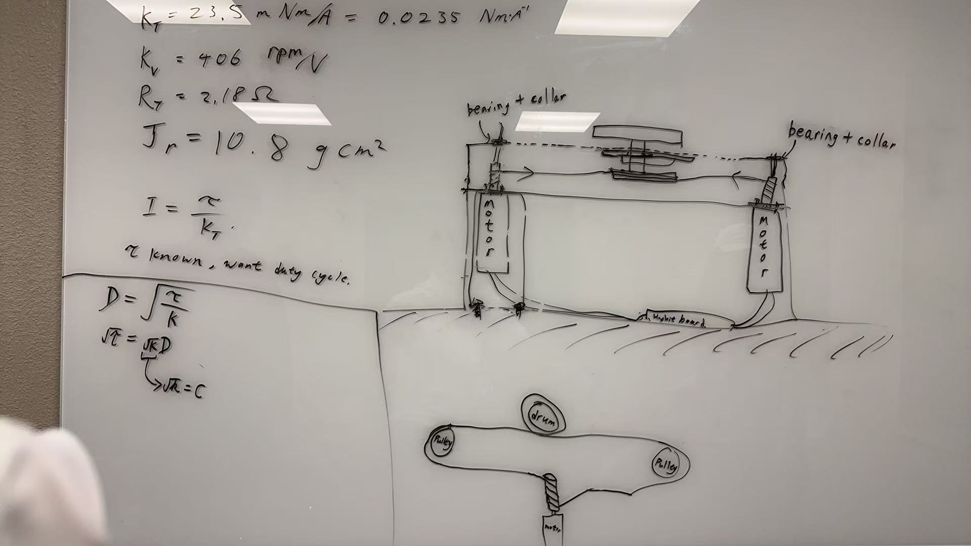
To control the motor torque via PWM, we begin with the basic torque–current relationship: I = τ / K
However, we do not directly control current; instead, we apply a PWM duty cycle to the motor driver. Since the motor is an inductive load, the motor current I is approximately proportional to the square of the duty cycle: I ∝ D^2 ⇒ D ∝ √I ∝ √τ
Based on this, we express the relationship as: D = √(τ / K) , √τ = √K · D
This expressions allow us to estimate the required PWM duty cycle D from a desired torque τ, using a fitted constant K to account for system-specific factors such as resistance and efficiency. To empirically get this coefficient, we did a linear least-squares between square root of the output torque against duty cycle. Data was obtained by hanging weights from the motor and measuring the duty cycle required to balance this weight as shown below.

The resulting plot is provided below.

Therefore, √K = 0.2128, K = 0.04528
Challenges
- PRL and other on campus labs with laser cutters require a safety training or orientation session before giving us access, but the earliest available PRL orientation is on this Friday.
- Hapkit board only has 2 interrupt pins and one Serial port. Since we're using 2 encoders, there seem to be a significant delay in Serial communication, we might need to use 2 Hapkit boards if this issue cannot be resolved.
- We derived the closed-form kinematics of the 8-bar linkage, but we're currently a little overwhelmed by the dynamics.
Checkpoint 2
Here you will write a few paragraphs about what you accomplished in the project so far. Include the checkpoint goals and describe which goals were met (and how), which were not (what were the challenges?), and any change of plans for the project based on what you learned. Include images and/or drawings where appropriate.
Fabrication
We laser cut acrylic boards to assemble the box. Its top layer has a hole to hold one joint of 8-bar linkage structure, two circular slits to hold other 3 joints, and one linear slit to hold the joint with the paddle and drum. The middle layer is used to hold two motors, the joint on the sector and two pulleys. Each board was held together by acrylic glue. And parts were fixed on the boards with shafts and collars. As designed in our proposal, the sector was connected to one of the motors with capstan. This motor tells us the position of the paddle. The drum, pulleys and the other motor were also connected with capstan. Two motors combined tell us the angle of the paddle.

Paddle Position Calculation (Assuming only linear region)
Complete Analysis
By plotting the derived expressions, the trajectory of the linkage would be:

where the critical points of the non-singular linear region are x=±0.12435 m, which is sufficient for the x=±0.1 m we're using for our device.
Furthermore, by comparing the full analysis to the simplified approximation:


The simplified expressions for position and torque calculation were used in our code, which takes up less computational power without losing any accuracy within the operation range.
Challenges
- Due to the complexity of the structure and tolerance in design and fabrication, the movement of the paddle is not very smooth. We are considering changing the cable of the capstan and add lubricant to each contacting point of joint and board.
- The motors were not very stable because of the force input/output, so we added a structure beneath them to hold.