

2025-Group 18

Caption: Final Assembly with All Components. From left to right: follower gripper, Arduino and breadboard, leader gripper, power supply.
Grippy: The Teleoperated Gripper
Project team member(s): Zach Sutherland; Haojun Feng; Shu Guo; Haocong Yang
Grippy is a low-cost, teleoperated robotic gripper system developed to investigate accessible solutions for haptic feedback in remote manipulation: particularly in constrained or hazardous environments where human presence is limited. Motivated by the need for an intuitive, bi-directional teleoperation device that is compact and simple, the project aimed to design a leader-follower system that could both mirror user input and reflect environmental contact forces back to the operator. The implementation involved custom CAD designs for two ergonomic grippers, 3D-printed in PLA, each powered by two different servo motors and outfitted with strategically placed force-sensitive resistors (FSRs). An Arduino-based control system was developed, using direct mapping of sensor input to motor output, bypassing the need for complex positional encoding. Throughout development, the team refined mechanical tolerances, optimized sensor placement, and tested different objects to grip to calibrated feedback loops to enable smooth and responsive operation. Despite limitations in sensor resolution and mechanical backlash, the system successfully demonstrated coordinated bidirectional control: the follower gripper mirrored finger motion from the leader, while applied forces from the environment were transmitted back as servo resistance. Functional at the system level and validated through physical testing, Grippy achieved its core goals and offers a scalable platform for future exploration of richer haptic interaction in teleoperated systems.
On this page... (hide)
Introduction
Teleoperation is an area of haptics particularly useful for mechanical work in harsh and hard-to-reach environments. These include high-temperature areas or claustrophobic rooms too small to directly work in. Accomplishing this task entails two major challenges. The first is ensuring the “leader” device (controlled by the user) accurately transmits its position in space to the “follower” device (controlled by the leader) to ensure the two move in unison. The second is transmitting force feedback from the follower back to the leader, allowing the user to detect the environment the follower is in (e.g. temperature, objects) through haptic sensations. This project aims to address both these challenges through a compact, low-cost teleoperated gripper system that acts as a proof-of-concept for larger, more sophisticated designs in the future.
This system features lightweight, circular force sensors on both the leader and follower gripper to transfer force feedback. Rather than using traditional position sensing in which the follower device calibrates its position using serial positional output from the leader, the arduino code for this system directly transfers force received by the leader’s sensors to the follower’s motor (after converting it to a calibrated angular step). Similarly, when transmitting haptic feedback from the follower to the leader, force received by the follower is directly transferred to the leader’s motor. This method removes the need for a position sensor (e.g. a magnetic sensor) to constantly track the leader’s position, enabling the use of servomotors - a more robust, accurate, and compact alternative to capstan drives. These benefits are vital for teleoperation in harsh or claustrophobic environments, where materials may face significant wear and tear and/or high precision may be required.
Background
Teleoperated robotic grippers have undergone significant developments in recent years, driven by the integration of force feedback, multimodal sensing, and intelligent control strategies. Traced back to nearly 10 years ago, the concept of the Haptic robot grippers started to emerge. The early foundational work by Li et al. (2016) introduced a hybrid teleoperation system combining vision and haptic feedback, significantly improving responsiveness and accuracy in remote manipulation tasks [3]. Coming up with the research from Zhou et al. developed the F1 Hand, a versatile and adaptive robotic gripper designed to accommodate a wide range of object shapes and manipulation needs in 2022, demonstrating the importance of mechanical adaptability in unstructured environments [6]. In recent years, more studies had been established, Hashimoto et al. (2023) proposed a novel control method using surface electromyography (sEMG) and force myography (FMG) signals to enable intuitive teleoperation based on human hand gestures [1]. Building on this, Iida et al. (2024) enhanced the bidirectional teleoperation framework with real-time force feedback, allowing for more precise control in dynamic interactions [2]. In parallel, Qin et al. (2024) introduced MagicGripper, which utilizes a multimodal approach—combining tactile, proximity, and visual inputs—to improve the performance of contact-rich tasks [4]. Most recently, Li et al. (2024) presented ACE, a cross-platform visual-exoskeleton interface that enables low-cost, dexterous teleoperation across various robotic platforms [5]. Together, these works represent the state of the art in teleoperated gripper design, revealing a clear trajectory toward more intuitive, sensor-rich, and adaptable manipulation systems capable of operating effectively in complex and uncertain environments.
Methods
The teleoperated gripper system consists of a pair of grippers, one being the leader and the other being the follower. Both grippers use servo motor direct drive as a power transmission method and FSR sensors to detect surroundings and apply feedback. At the user interaction area of the leader gripper, there are two FSR sensors placed on the inside and outside of the user’s finger. When the user moves to close the leader gripper, the inner FSR sensor senses force and closes the leader gripper, and when the user moves to open the leader gripper, the outer FSR sensor senses force and opens the leader gripper. The follower gripper only has an FSR sensor on the inside of the gripper to sense the force applied to the gripped object. During use, the controller compares the force sensed by the force sensor and moves the leader gripper accordingly.
When in use, both the follower and leader gripper are grounded. The user manipulates the opening and closing of the leader gripper, and the follower gripper follows the motion of the leader gripper. When the follower gripper is not interacting with an object, the leader gripper moves freely, with the follower following the opening and closing of the leader gripper. But when the follower gripper interacts with an object, the user feels resistance on the leader gripper proportional to how much force they apply and dependent upon the object being held.
Hardware Design and Implementation
The leader and follower grippers have very similar designs. The main design difference is that the follower gripper fingers have a bigger contact area for better gripping. The leader gripper has a raised surface platform to house the user’s finger when they are operating the gripper. An elevated platform was designed for operation to avoid the servo getting in the way of the user operating the system.
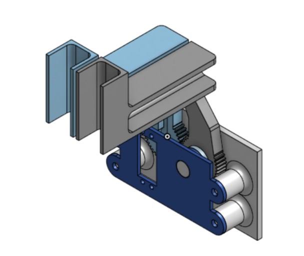
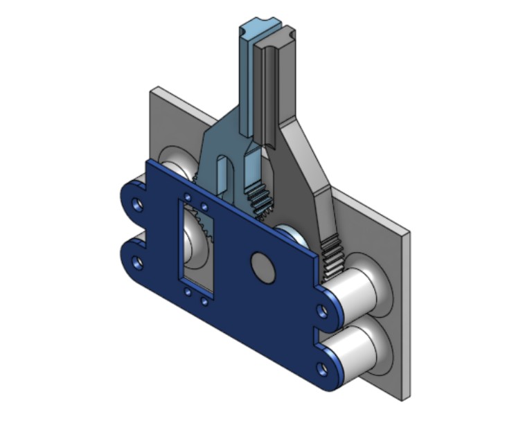
The mechanisms of the leader and follower grippers are also very similar. The two fingers on each gripper are coupled at the base by a gear system, allowing both fingers to open and close at the same angle. Both the leader and follower gripper are powered at the base with a 180-degree servo motor directly attached to one of the gripper fingers. However, the follower gripper uses a 20 kg*cm servo while the leader gripper uses a 3 kg*cm servo. The leader gripper servo’s strength is significantly lower out of concern that the 20kg*cm servo could injure users during use due to its strong torque output.

Figure 1. Leader and Follower Gripper.
As for the electronic system, both the leader and follower gripper servos are powered by a HiLetgo PCA9685 PWM servo motor driver. The servo motor driver allows for powering the servo motors with an external power supply with a higher voltage, giving more power to the servo. The primary microcontroller used is an ELEGOO Mega 2650 microcontroller. This controller was chosen because it has a lot of analog input pins.

Figure 2. System Electronic
In this system, a total of six thin film pressure sensors sense the force applied to the system. Four sensors are attached to the finger platform on the leader gripper. These detect the force the user applies to the system, allowing the user to control the grippers. The leader sensor locations were chosen based on user testing to determine the optimal ergonomic placement. The other two sensors are located on the follower gripper to detect when an object is being gripped and provide force feedback. After testing to determine what locations provided the best sensing, these sensors were placed at the tip of the follower gripper. A 20K resistor acts as a voltage divider for all the sensors, allowing the ELEGOO Mega to correctly read them. This is because, after testing with a 100K resistor, 50K resistor, and 20K resistor, the 20K resistor provided the best sensitivity and force reading range.

Figure 3. Senser placement
System Analysis and Control
Unlike traditional haptic systems, Grippy uses admittance haptic control instead of impedance haptic control. This means instead of using position data to output a force feedback, Grippy uses force data to provide positive feedback. Thus, Grippy relies heavily on its six pressure sensors to provide haptic feedback, named FSR1 to FSR6. FSR1 to FSR4 are on the leader gripper to detect the user’s motion, while FSR5 and FSR6 are on the follower gripper. FSR1 is placed on the outside of the thumb; FSR2 is placed on the inside of the thumb; FSR3 is placed on the inside of the index finger; FSR4 is placed on the outside of the index finger; FSR5 and FSR6 are both placed on the inside tip of the follower gripper’s fingers.
An attempt was made to calibrate the pressure sensors with a scale, but it was unsuccessful because the sensors are too small and too sensitive. Therefore, it was assumed that all six pressure sensors behave similarly and have a linear relationship between the sensor readings and the force applied to them. Further devices were used to divide all FSR sensor readings by 10 to dampen the sensitivity. This was done because, when testing without the damping, the sensitivity of the sensors tended to cause the system to oscillate as soon as the follower gripper contacted an object.
Regarding the function of each pressure sensor, FSR1 and FSR4 detect the opening of the leader gripper, FSR2 and FSR3 detect the closing of the leader gripper, and FSR5 and FSR6 detect if the follower gripper is gripping an object. The readings of the six sensors are compared in this logic to determine the motion of the leader and follower grippers. The average of the FSR1 and FSR4 readings determines the force applied to open the gripper, while the average of the FSR2 and FSR3 readings determines the force applied to close the gripper. The net force applied by the user to the leader gripper is calculated by subtracting the opening force from the closing force. For this calculation, it is assumed that the net force on the leader gripper is positive when the opening force is greater than the closing force. On the follower side, the average of the FSR5 and FSR6 readings is used to determine the resistance provided by the object in order to calculate feedback to the leader gripper. The total system force is calculated by adding the force on the leader side to the sum of the forces on the follower side, and the servo step is determined by multiplying the total system force by a step factor. During operation, a positive total system force results in the gripper opening, while a negative total system force causes the gripper to close.

Testing revealed the need to bias the leader gripper size input. When the force on the leader side was added to the sum of the forces on the follower side at a 1:1 ratio, the system tended to oscillate when the follower was in contact with an object. Further testing indicated that the ratio between the force on the leader side and the sum of the forces on the follower side should be less than 1; however, if the ratio is too small, the system becomes unresponsive. An optimal ratio of 0.6:1 was determined through experimentation (Figure 4). Additionally, testing showed that the step factor should be set to 0.15. A step factor that is too small causes lag and unresponsiveness, while a value that is too high results in oscillations during gripper operation (Figure 5).
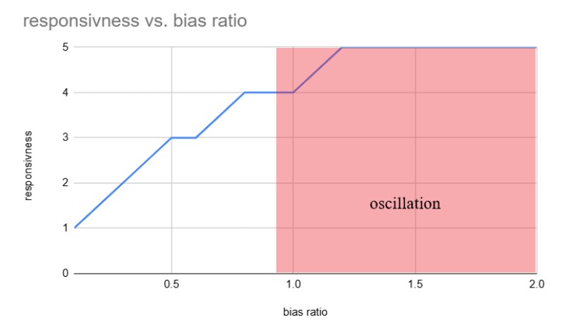
Figure 4. Follower Gripper bias ratio analysis

Figure 5. Step factor analysis.
Demonstration / Application
The team successfully developed a working teleoperated haptic gripper. Users can control the gripper to move smoothly in free space, and when the follower gripper is in contact with an object the leader gripper lets the user feel the object at a noticeable level.
Link to video demonstration: https://photos.app.goo.gl/2oXuDHRnHFXeQwKQ7
Though successful, the system still has multiple shortcomings. The leader gripper is not as robust as it could be, due to the use of a significantly weaker servo on the leader gripper compared to the follower gripper. This design choice was made for safety reasons, but it allows the user to overpower the servo on the leader gripper without the system detecting it, which reduces the realism of the experience. Additionally, the pressure sensors used are very low-cost components, resulting in limited precision and accuracy. The ergonomics of the finger platform design could also be improved to better accommodate a wider range of users.
Results
There were four primary objects used to evaluate the force feedback of the final device: an AirPods case (high stiffness), a banana (medium stiffness), a rectangular tissue bag (low stiffness), and an apple (larger size). When the follower gripper contacted the AirPods case and banana, the force feedback on the leader gripper performed quite well. There was a sharp increase in resistance to motion upon contact, scaling up to the maximum power of the leader servo the more the user pushed. However, for the tissue bag, force feedback was slightly less noticeable. This may be attributed to the weakness of the leader servo. Due to the tissue bag’s low stiffness, force feedback must increase more gradually with displacement than for the Airpods case and banana. The low 3 kg*cm max output from the leader likely meant this increase was too gradual for easy detection. When using the apple, force feedback worked well as with Airpods and banana; however, there was some difficulty aligning the larger apple with the force sensors between trials due to the radial movement of the follower. This opens up a potential avenue for future work to be discussed in the next section.
Users at the open house responded positively to Grippy, calling it a unique system that worked surprisingly well for how compact it was. They also noted that the follower gripper followed the leader’s position well and that the force feedback from the demo’d objects (AirPods case, banana) was clearly noticeable. On the side of critiques, as anticipated, users said that it was rather easy to overcome the resistance from the leader servo. Furthermore, they noted a slight jumpiness to the movement of the leader in free space - a likely product of the low-cost leader sensors with suboptimal reliability in exact force detection.
Future Work
As previously mentioned, this system serves as a proof-of-concept for a future gripper that could be used in tasks like arranging objects in out-of-reach or hazardous environments. The biggest area for improvement is the strength of the leader gripper’s servo. For this prototype, a 3 kg·cm torque servo was used on the leader side to ensure safety and avoid applying excessive force to the user’s fingers. While this made the system safe and comfortable to use, testing feedback showed that the force feedback from the follower gripper felt too weak to be noticeable in many cases. On the follower side, a 20 kg·cm torque servo was used to provide strong and reliable object gripping. The mismatch between the follower’s gripping force and the leader’s feedback force limited how much feedback the user could actually feel.
In the future, it would be worthwhile to test a mid-range option—such as a 10 kg·cm torque servo—on the leader side. This could offer a better balance between user safety and the strength of haptic feedback, helping the user better perceive when the follower gripper interacts with an object. Additional improvements could include expanding the sensing area on the follower gripper by adding more FSRs or using larger ones to improve force detection coverage. Furthermore, future designs could implement a rack-and-pinion system on the follower gripper to change radial movement to translational movement, improving reliability with larger objects such as the apple. As a whole, these updates would make the feedback loop more consistent and improve the system’s overall responsiveness and usability.
Acknowledgments
We'd like to thank the course assistants (Ryan and Teo) as well as Professor Okamura for their ideas and support throughout the design and development of this project.
Files
Component design:
Grippy Leader Gripper Design:
Grippy Follower Gripper Design:
Component STL File for 3D Printing: Attach:GrippySTL.zip
Bill of Material for Other Components:
ELEGOO MEGA R3 Board ATmega 2560: https://www.amazon.com/dp/B01H4ZLZLQ?ref_=ppx_hzsearch_conn_dt_b_fed_asin_title_3&th=1
Force sensitive resistor thin film pressure sensor: ppx_yo2ov_dt_b_fed_asin_title?
20KG RC Servo High Torque Servo Motors: https://www.amazon.com/dp/B073F92G2S?ref_=ppx_hzsearch_conn_dt_b_fed_asin_title_1&th=1
Arduino Control Code: Attach:GrippyCode.ino Δ
include <Wire.h> include <Adafruit_PWMServoDriver.h>
// servo driver set up Adafruit_PWMServoDriver pwm = Adafruit_PWMServoDriver();
// PCA9685 servo settings const int servoMin = 102; // Minimum pulse length count (approx 0°) const int servoMax = 512; // Maximum pulse length count (approx 180°)
// Servo channels const int leaderServo = 1; const int followerServo = 0;
// home servo angle int angle = 95;
// sensor set up
// === Pins === // leader gripper const int fsr1Pin = A1; const int fsr2Pin = A3; const int fsr3Pin = A5; const int fsr4Pin = A7;
// follower gripper const int fsr5Pin = A9; const int fsr6Pin = A11;
int FSR1 ; int FSR2 ; int FSR3 ; int FSR4 ; int FSR5 ; int FSR6 ;
void setup() {
  // put your setup code here, to run once:
  Serial.begin(9600);

  // servo driver
  pwm.begin();
  pwm.setPWMFreq(50);  // Analog servos run at ~50 Hz

  // FSR sensor
  pinMode(fsr1Pin, INPUT);
  pinMode(fsr2Pin, INPUT);
  pinMode(fsr3Pin, INPUT);
  pinMode(fsr4Pin, INPUT);
  pinMode(fsr5Pin, INPUT);
  pinMode(fsr6Pin, INPUT);
}
void loop() {
    int FSR1 = analogRead(fsr1Pin)/10;

  int FSR2 = analogRead(fsr2Pin)/10;

  int FSR3 = analogRead(fsr3Pin)/10;

  int FSR4 = analogRead(fsr4Pin)/10;

  int FSR5 = analogRead(fsr5Pin)/10;

  int FSR6 = analogRead(fsr6Pin)/10;
  void force();
  void servo();

  int F_leader_out = ((FSR1+FSR4)/2);
  int F_leader_in = ((FSR2+FSR3)/2);
  int F_leader = (F_leader_out - F_leader_in); direction out if +

  int F_follower = (FSR5 + FSR6)/2; // outward

  int F = 0.5*F_follower + F_leader;

  int step = F * 0.15;  // step = f(F) to be changed

  angle = angle + step;
// safety limit
  if (angle < 90 ) {

      angle = 90;

    }

     if (angle > 130 ) {

      angle = 130;

    }

    int leaderpulse = map(angle+5, 0, 180, servoMin, servoMax);
    int followerpulse = map(angle-5, 180, 0, servoMin, servoMax);

      pwm.setPWM(leaderServo, 0, leaderpulse);
      pwm.setPWM(followerServo, 0, followerpulse);

  Serial.print("FSR1: ");   Serial.print(FSR1);
  Serial.print(" FSR2: ");  Serial.print(FSR2);
  Serial.print(" FSR3: ");  Serial.print(FSR3);
  Serial.print(" FSR4: ");  Serial.print(FSR4);
  Serial.print(" FSR5: ");  Serial.print(FSR5);
  Serial.print(" FSR6: ");  Serial.print(FSR6);
  Serial.print(" Moved to angle: ");  Serial.println(angle);
}
References
1. Hashimoto, A. et al., "Teleoperation of a Robotic Arm using sEMG and FMG Signals," JACIII, 2025.
https://www.jstage.jst.go.jp/article/jaciii/29/1/29_79
2. Iida, T. et al., "Bi-Directional Force Feedback and Vision-Based Teleoperation," arXiv preprint arXiv:2502.07730, 2024.
https://arxiv.org/pdf/2502.07730
3. Li, Y. et al., "Hybrid Teleoperation Combining Vision and Force Feedback," IEEE, 2016. https://ieeexplore.ieee.org/document/7479565
    Qin, L. et al., "MagicGripper: Learning Contact-Rich Multi-Modal Manipulation," arXiv preprint arXiv:2505.24382, 2024.
    https://arxiv.org/abs/2505.24382
4. Li, H. et al., "ACE: A Cross-Platform Visual-Exoskeleton for Dexterous Robot Teleoperation," arXiv preprint arXiv:2408.11805, 2024.
https://arxiv.org/abs/2408.11805
5. Zhou, Y. et al., "F1 Hand: A Versatile and Adaptive Robotic Gripper," arXiv preprint arXiv:2205.07066, 2022.
https://arxiv.org/abs/2205.07066
Appendix: Project Checkpoints
Checkpoint 1
The goals of this checkpoint were to develop a concept prototype, purchase electronics, and complete the system CAD. Overall, we were successful in accomplishing these goals.
The concept prototype was completed on time using cardboard cutouts to simulate the ergonomics and geometrical feasibility of the final device. We went through three different iterations of the design, with the main changes between iterations being the mounting location of the leader gripper motor and the orientation of the human interactive component. One challenge that came with this was ensuring the user could securely hold their finger between the force sensors and push against them without shifting or tilting the system (only rotation). The final design is shown below. It involves two pivot points (one per holder) to mitigate translational motion and a high surface area weight at the base (representing the motor) to mitigate tilting.

Figure 1: Final concept prototype for the leader gripper. The left image shows the finger holders, while the right image shows the base weight.
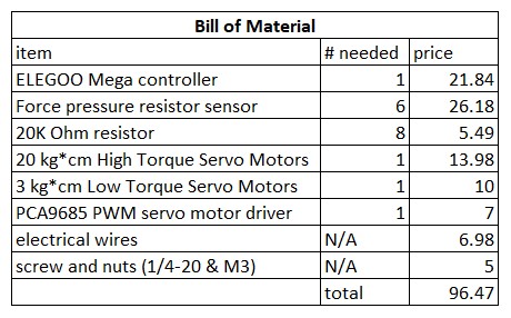
We purchased the electronics for the project on Amazon without any major roadblocks. These were the items we listed in our proposed bill of materials on our project proposal: 1 ELEGOO Mega controller, 8 Force pressure resistor sensors, 8 10 kOhm resistors, 2 High Torque Servo Motors, and numerous electrical wires, screws, and nuts. We have since received all ordered materials and are ready to begin hardware development.
The CAD model for the system was edited from the first version (included in the project proposal) based on the leader gripper concept prototype discussed above. This was completed two days before our set deadline and posed minimal challenge. The final model is shown below:

Figure 2: Current CAD for the follower gripper (left) and leader gripper (right).
After 3D printing several components of this CAD model, we discovered some room for further improvements in the ergonomics of the finger holders. In addition, our tolerancing for the gap between the finger holders and base piece (to ensure low friction) was too lenient, leading to some unwanted wiggling. These issues will lead to a slight increase in workload next week, but not significant enough to notably change project plans. The 3D printed grippers are shown below.

Figure 3: 3D printed follower (left) and leader (right) grippers.
Our primary plan of action for the coming week is to complete the bulk of the calibration and force feedback code. For this purpose, the team recently met to discuss the gripper code logic and delegate coding tasks.
Checkpoint 2
The goals of this checkpoint were to 3D print components (completed in the previous checkpoint), finish the sensor calibration and gripper servo code, and start on the final system assembly. With the exception of the sensor calibration (see next paragraph), all of these goals were met. The force sensors were found to be too small to reliably adjust sensitivity. However, after testing, when a small amount of pressure was applied directly on each force sensor, servomotor responses were consistently heard. Thus, we determined that the lack of sensitivity adjustment was a negligible issue. The sensors’ size, however, poses a challenge; users currently need to be quite precise when grabbing an object with the follower gripper for the object to touch the attached force sensors. As a result, we may need to add more sensors across the length of both follower gripper clamps to reliably detect force input from objects.
At the same time, we began developing the overall control code for the full system integration. The code was divided into three main parts, with each team member responsible for one section. These components were later combined into a unified system. The first part of the code handled general button controls for managing the system’s overall state. This included the start, stop, zero, and home button circuits, along with the corresponding code to interface with the physical buttons. The second part focused on reading output from various force sensors via the Arduino serial monitor. We encountered a coupling issue among the six sensors. Specifically, one sensor would interfere with its immediate neighbor. After some root cause analysis, we determined the issue stemmed from a software-related problem within Arduino, which we resolved. Initially, we used 100 kOhm resistors in the sensor circuit, but this made the sensors overly sensitive, causing the force readings to saturate with minimal input. We experimented with lower resistance values, trying 50k and 20k, and found that 20k provided the best balance of resolution and sensitivity. This was adopted in the updated design. The third part involved position control for the gripper motions and force feedback on the leader side. In the first iteration, we implemented a complex logic that integrated acceleration to compute angular velocity and position for servo motor control. However, this approach proved unnecessarily complicated. We revised the logic to a simpler version that directly compared angular movements on the leader side and mapped them to corresponding angle inputs.
Hardware-wise, we are ahead of schedule. In addition to the 3D printed components from the first checkpoint, we’ve successfully integrated an Arduino board, breadboard, and power supply with wires to all key locations. The current assembly is shown in the picture below.
Figure 4: Current hardware assembly. From left to right: follower gripper, arduino and breadboard, leader gripper, power supply.
We were also able to integrate the previously discussed code into the system, giving us a preliminary look at what the dynamics of the final system will look like. The video below shows the follower gripper approximately mirroring the leader gripper as a user applies force on the leader’s force sensors. It also shows the leader gripper reacting to a force applied on the follower gripper’s sensors, simulating the force feedback from an object’s presence.
Link to video: https://photos.app.goo.gl/2oXuDHRnHFXeQwKQ7
For the last week, we will determine where to best place the follower gripper’s force sensors (or add more of them if possible) to produce the most reliable force feedback when grabbing an object. We will also start on the report in the next couple of days, with the plan of completing it by June 3 (one day before the due date).