2025-Group 2

Demonstration setup
Haptic Manual Transmission Shifter
Project team members: Rachel Grant, Ngorli Paintsil, Kristie Park, Sam Sternfels, and Diego Stone
Our project is to create a haptic manual transmission shifter that can teach users how to drive manual cars. Commonly, users learn how to drive manual cars in-person through a family member or friend. This can cause premature wear or damage to the car due to improper use while learning. Additionally, some prospective drivers may feel intimidated by learning a new type of transmission while also driving on public roads in a real world environment. Our goal is to simulate and provide an environment where people can practice engaging the clutch and shifting gears according to the vehicle�s speed and/or RPM. Overall, we were successful in that the two components�the clutch pedal and stick�were well incorporated in the design. Paired with the visual dashboard displaying the vehicle�s speed and RPM, people ranging from first time to experienced drivers were able to successfully shift up to sixth gear and a speed of roughly eighty mph.

Introduction
The primary goal of our haptic device is to teach the fundamentals of manual driving without the risk of damaging a real vehicle. Designed as a teaching tool and practice device, it will help users develop an intuitive understanding of gear shifting by providing tactile feedback to guide users in the right direction and indicate what should feel wrong. Ultimately, this device creates a safe, low stakes and low stress environment for users to learn to drive a manual transmission.
Background
Prior work in haptics has demonstrated the effectiveness of tactile feedback in simulating realistic mechanical interactions and improving motor skill acquisition. Angerilli et al. (2001) developed a two-degree-of-freedom haptic device to replicate the physical resistance of a manual gear shift, showing how such feedback can enhance realism in driving simulators [1]. Lee et al. (2021) used neural networks to model expert driving behavior and apply performance-based haptic feedback to novice drivers, finding improvements in steering performance, though not in pedal control�highlighting haptics' utility for gross motor training [2]. Similarly, Morris et al. (2007) showed that haptic and visual cues together significantly improved the learning of force-based tasks compared to either modality alone, suggesting haptics can directly aid in force skill learning [3].
Methods
Hardware Design and Implementation
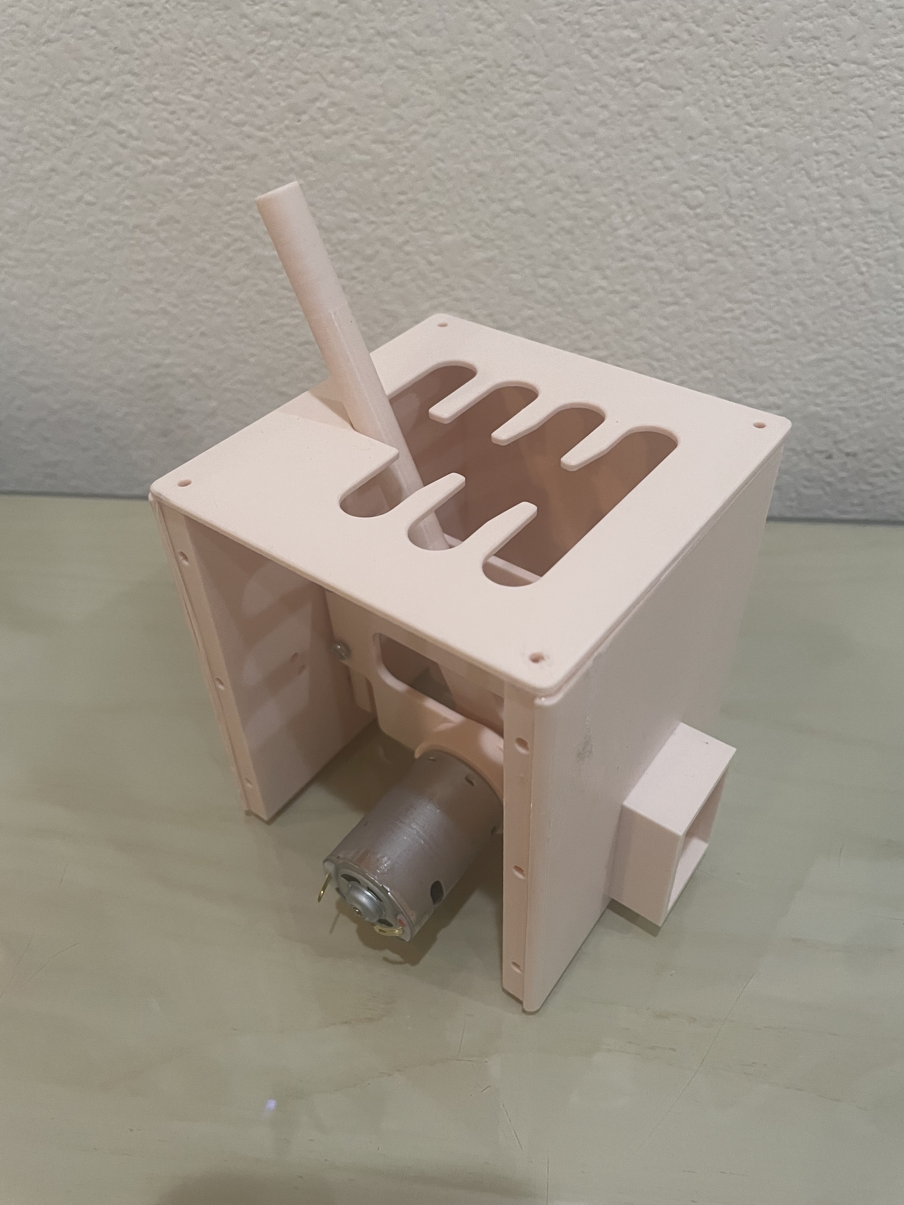
For the stick shift, we designed a two-degree-of-freedom system controlled by two motors, with each degree-of-freedom dictated by a miniature version of the Hapkit used in the ME 327 course. Position readings from each Hapkit were used to determine which gear the user was in, in conjunction with haptic feedback responses (detailed further in the Arduino and Electrical Integration section).

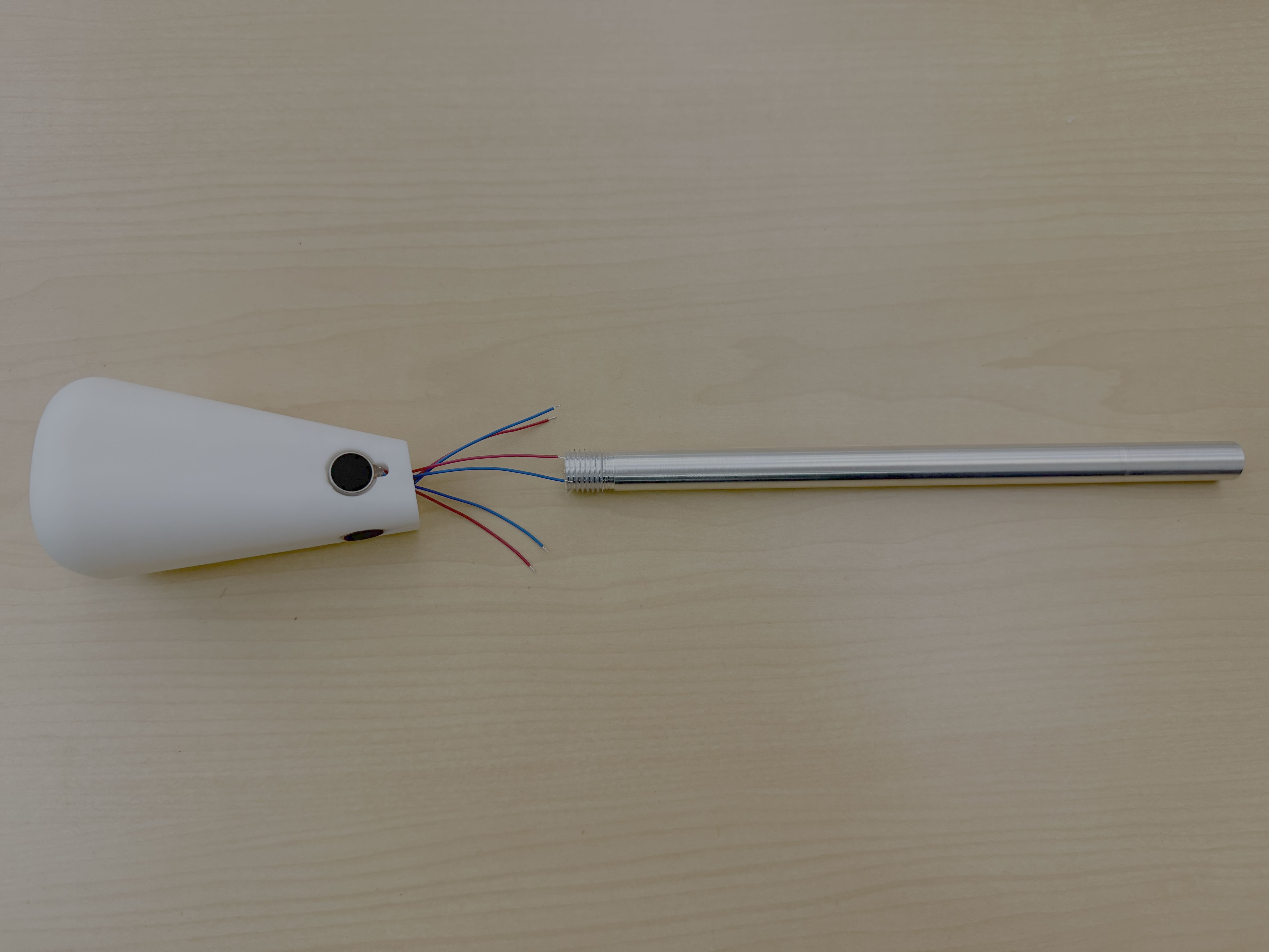
The stick itself consisted of a machined shaft with a 3D-printed knob. The knob featured an embossed gear pattern on the top surface and included finger holds to encourage users to grip it with two fingers. This design choice was based on our observations that aggressive one-handed use led to inconsistent sensor readings�using two fingers helped promote more controlled interaction.


The housing walls were fitted with bearings to allow smooth rotation of the rods. Additionally, we included a cantilevered extension on the side of the housing, enabling the entire assembly to be securely clamped to a table. The final setup looked like this:

For the pedal, we based our design on a model by CNCDan [4], making several modifications to integrate it into our system. We incorporated a Hall-effect sensor to detect the position of an embedded magnet, effectively turning the pedal into a digital limit switch�registering either a pressed or unpressed state. We modified the housing brackets and structural components to accommodate our sourced hardware and widened the overall assembly to allow the pedal to be pressed to a lower angle, enhancing its realism. Finally, we added an outer housing and secured the base to the floor using Velcro to keep it stable during use.
System Analysis and Control
Since we reused the Hapkit design, we used the same kinematics with the new dimensions to find applied torques. We used the same angle sensor and Hapkit template code to measure the movement of the hapkit in each axis. The kinesthetic feedback acts in each axis, where a constant force can be felt as we enter each gear. We used a constant force at the end of the handle of 1N opposite of the direction of movement to simulate shifting into gear where we drive the motors when the handle is detected in certain angle regions. We opted to use a constant force rather than a virtual wall or spring because it felt more accurate than a force that increase with movement. When the clutch is engaged the vertical haptic effect disappears but we still retain the horizontal force to simulate the handle being centered around neutral. Additionally, the vibration motors are used to simulate engine vibrations that can be felt through the handle when the transmission is in gear. When we engage the clutch the vibrations stop to simulate the feeling of being disconnected from the engine and return when the transmission is back in gear.
Arduino and Electrical Integration
For our setup, we used two Arduinos to control all of the haptic feedback for the physical device and state estimation for the virtual dashboard. The main Arduino took in analog output from the Hall-Effect sensor on the clutch, the analog output from MR sensors on the stick shift device, and powered the motors. This was also the Arduino that was connected to the laptop. The secondary Arduino controlled the vibration motors on the handle that simulated the light engine rumbling. To communicate between the two Arduinos, the output from a digital pin from the main Arduino was connected to the input for the secondary Arduino, signifying that the clutch was down and the handle vibration should pause to simulate the engine feel. There were two breadboards mounted on the haptic device, which were used for common grounds and common power.
Arduino Code
The Arduino code had several key sections that made up the full haptic experience. Using the same MR sensor parsing logic as taught in class, values for both axes of the stick�saved as our vertical and horizontal updated positions�were tracked. Another sensor value that was read and monitored was from the Hall effect sensor. The first condition involved checking whether the Hall effect sensor value had surpassed our measured threshold for when the clutch was pressed down. This value was printed to the serial monitor as either one or zero.
Next, we implemented a series of positional thresholds in the x and y directions to convert the horizontal and vertical position readings into gear mappings. This allowed us to discretize the gear space into a 3x2 grid. To determine the current gear, we checked the x and y position of the handle and identified the region of the gearbox that the point fell into.
To generate additional haptic feedback as the stick moved, we created bumps and valleys corresponding to gear transitions. The valleys were positioned at the edges of the gear slots�such as all the way forward in the left column for first gear or all the way back in the middle column for fourth gear�and one central valley was placed at the center of the device. The bumps were placed between these clutch valleys and the central �neutral� valley, simulating the intermediate transitions between gears.
The code for the vibration motors checked whether a gear change was occurring by comparing the current gear to the previously registered gear. If a valid gear change was detected�validated by the clutch state�the vibration motors would pause briefly to simulate a physical transition. As described earlier, the main Arduino would send a HIGH or LOW signal to a digital pin on the secondary Arduino, allowing the secondary unit to adjust its state accordingly.
Virtual Display
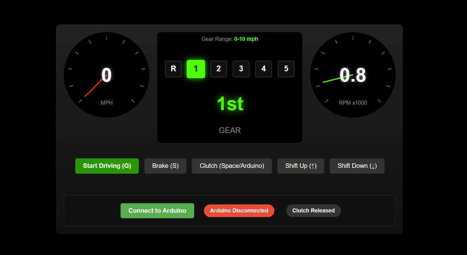
To enhance the interactivity and realism of our project, we developed a virtual dashboard that displayed key information to the user, including the current gear, speed, RPM, and clutch status. The display also served as the front end for connecting and disconnecting to the Arduino, as well as for starting and stopping the driving simulation. We built the interface as a locally hosted HTML website, using CSS for styling. This approach allowed us to create a clean, intuitive site that could dynamically update in real time based on both user inputs and Arduino outputs.
To handle data from the Arduino, we implemented a JavaScript script that read the serial output from the Arduino port. The script parsed the data and passed the resulting values to the HTML frontend. The data string from the Arduino was formatted as clutch,gear, where clutch was either 0 or 1 depending on whether the clutch was engaged, and gear ranged from 1 to 6 based on MR sensor readings.
The main feature of the visual display was a speedometer that linearly increased the user's speed, with RPM increasing accordingly. The dashboard would only update the displayed gear when the clutch was engaged. If the user failed to shift gears before reaching approximately 6500 RPM, the display would �redline,� flashing red and causing the RPM needle to shake�providing a clear and immersive warning signal.

User in first gear

User in first gear redlining

User in third gear
Demonstration / Application
In our demonstration we introduced our device by asking users if they had a background with manual transmission vehicles. The range of responses was quite varied with some saying they own a manual car and others asking, �What is a clutch?� Depending on their level of familiarity, we introduced the concept of manual transmission and how our device simulates it. We noted one difference with our device compared to actuality was that with ours you begin in first gear rather than neutral. Next, we would prep the user on what our demonstration entailed: shifting from first to sixth gear watching their speed and RPMs on the visual display. Finally, we would select �start driving� and let the user test their driving skills.


Results
We received largely positive feedback on our haptic training device during the open house. After using the system, participants completed a brief survey about their experience. Sixty percent of users reported having prior experience driving a manual transmission vehicle, while forty percent did not. Despite this range in experience, seventy-five percent of respondents felt that the simulation was realistic and helpful in preparing for real-world manual driving. Additionally, sixty percent of users stated that interacting with the device increased their confidence in their ability to drive a manual car. These responses suggest that the device is both accessible to beginners and valuable for building driving confidence.
Future Work
Our system could be tested with participants of varying manual driving experience and after tries on our haptic device, measure their gear-shifting accuracy and driver confidence over time. This system could then be used as a more cost-effective learning tool for manual transmission education prior to driving a vehicle.
The stick shift could be refined with more realistic force feedback and higher-resolution sensors. A few additional software and audio feedback features might include engine sounds or stall simulations. On the hardware side, an improved model could include a brake and accelerator pedal on top of a clutch pedal for a more realistic understanding of the foot motion during driving.
Files
HTML Code: Attach:HTML_Code.pdf
Javascript Code: Attach:Javascript_Code.pdf
Arduino Code: Attach:Arduino_Code.pdf

Exploded chassis CAD

Knob CAD
Bill of materials: https://docs.google.com/spreadsheets/d/1-7tILDHfL8exPJ9OTpW3Dvf1z2IjS4rgI5fvwjYrFes/edit?usp=sharing
References
[1] M. Angerilli, A. Frisoli, F. Salsedo, S. Marcheschi and M. Bergamasco, "Haptic simulation of an automotive manual gearshift," Proceedings 10th IEEE International Workshop on Robot and Human Interactive Communication. ROMAN 2001 (Cat. No.01TH8591), Bordeaux, Paris, France, 2001, pp. 170-175, doi: 10.1109/ROMAN.2001.981897. keywords: {Haptic interfaces;Gears;Force measurement;Couplings;Force sensors;Shafts;Filling;Kinematics;Force control;Virtual environment},
[2] H. Lee, H. Kim and S. Choi, "Driving Skill Modeling Using Neural Networks for Performance-Based Haptic Assistance," in IEEE Transactions on Human-Machine Systems, vol. 51, no. 3, pp. 198-210, June 2021, doi: 10.1109/THMS.2021.3061409. keywords: {Haptic interfaces;Artificial neural networks;Wheels;Torque;Brakes;Vehicles;Performance evaluation;Artificial neural networks;driving skill;haptic assistance;haptic shared control;motor performance;simulated driving},
[3] D. Morris, H. Tan, F. Barbagli, T. Chang and K. Salisbury, "Haptic Feedback Enhances Force Skill Learning," Second Joint EuroHaptics Conference and Symposium on Haptic Interfaces for Virtual Environment and Teleoperator Systems (WHC'07), Tsukuba, Japan, 2007, pp. 21-26, doi: 10.1109/WHC.2007.65. keywords: {Force feedback;Haptic interfaces;Surgery;Shape;Force measurement;Education;Spatiotemporal phenomena;Virtual environment;Computer science;Laboratories},
[4] D. McKeen, SimPedals: DIY Load Cell Sim Racing Pedals, GitHub, 2022. Available: https://github.com/dmcke5/SimPedals
Appendix: Project Checkpoints
Checkpoint 1
Our Checkpoint 1 goals were to purchase all of our components, print a prototype of our assembly, and have a first iteration of the visual display completed. We were able to achieve each of these goals!
Components
We took a little field trip over to Jameco Electronics and purchased our motors as well as our Hall effect sensor. We selected a 12V DC brush motor with 3400 rpm (product number: 2310031) and a 3V 3-pin linear Hall effect sensor (product number: 1915940).
Prototype
We built a first iteration of the shifter, modeling how our motors and sensors would be mounted relative to the shifter. From this, we noted the tolerances to update and created a list of design changes to make such as mounting the sensor onto the inner box to ensure the magnet stays the same distance from the sensor and adding a spring to ensure the shaft stands up straight when no motors are running, as the weight of the motor currently pulls it down to rest at an angle.


Visual Display
For our visual display, we developed an interactive website simulating a manual transmission car dashboard. The interface includes a speedometer, tachometer, and gear indicator, all of which dynamically respond to user inputs. Users control the simulation with keyboard commands: 'G' to start/stop driving (with constant acceleration), 'S' to brake, 'Spacebar' to engage the clutch, and 'Arrow Up'/'Arrow Down' to shift gears. The dashboard visually responds to these actions, with the gear display changing to red if the engine redlines, helping them know when to shift gears.

Checkpoint 2
Our Checkpoint 2 goals were to have integrated our entire assembly and completed some initial programming to verify the hardware capabilities.
After looking at other teams' work we were inspired to inlay our vibration motors in the handle rather than trying to adhere them to the interior face. To do this, we slightly changed the design of our handle and added small indents for the vibration motors to sit in. Even with this change, the wiring from the vibration motors is still fed internally down the shaft. We also upgraded from a 3D printed shaft to an aluminum shaft that we turned down to the proper size.
We put together our complete chassis and began to do preliminary testing of our setup. We quickly noted that our direct drive motors could not produce a large enough torque that was noticeable to the user. And so, we bought 12V DC geared motors that can produce a much higher torque (15 kg cm). Upon their arrival, we integrated these motors into our system and found they were able to produce a torque that the user could readily notice.

Using an open source pedal design as inspiration, we created our pedal with some adjustments to fit our own design requirements. For example, we had to resize the spring to provide a more accurate user interface. We used a linear hall effect sensor and magnet to detect the depression of the pedal.
\
Initial Programming
Our virtual display is now integrated with our arduino code. To test this code, we used a limit switch to simulate the clutch crossing the engagement threshold, and were able to successfully use our limit switch to engage the clutch in the setup. We also have our outlined arduino code that will be integrated with the hardware as it is finished.