

2025-Group 4
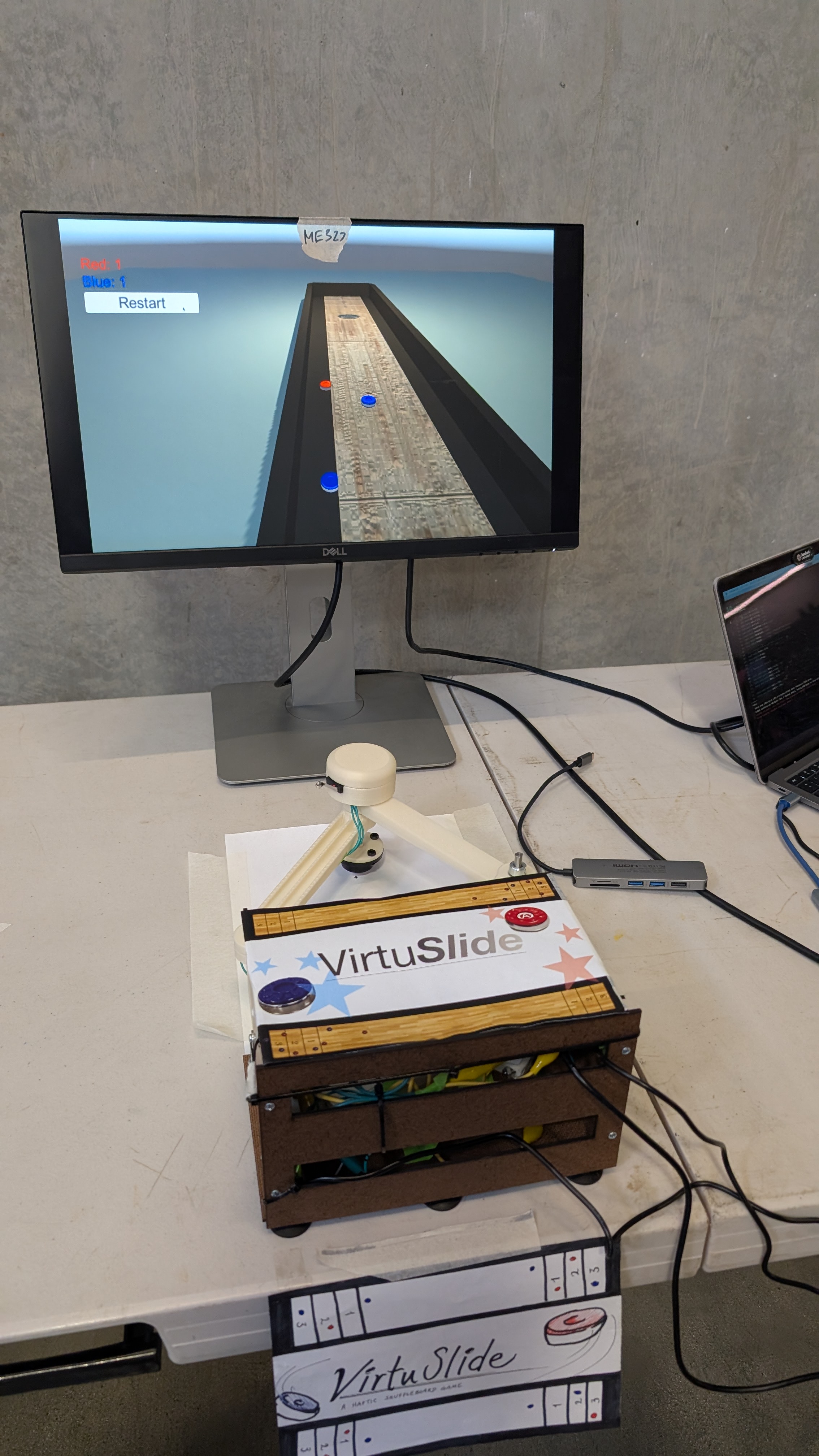
VirtuSlide during the 2025 Haptics Open House
VirtuSlide:
Haptic Shuffleboard
Project team members: Xiangmei Chen, Zin Yamin Tun, Sam Chen, Annika Yong
This project focuses on creating a haptics-driven virtual shuffleboard game using a 2DOF pantograph system to provide realistic physical feedback. The motivation behind this is to bring the kinesthetic and tactile experience of playing shuffleboard into a virtual environment, allowing users to feel the motion of the puck, the resistance of the sandy surface, and the boundaries of the game field. By integrating sensors, motors, and a button on the physical puck, we track user input and translate it into dynamic feedback, such as the puck's inertia and collisions with virtual obstacles. Our goal is to combine physics-based modeling with haptic control to give users an immersive and engaging experience, where they can "feel" the game just like they would in real life. The result is a system that brings the fun and challenge of shuffleboard to life in a virtual space, with a strong focus on user interaction and dynamic feedback.
On this page... (hide)
Introduction
The motivation for our project stems from a desire to explore the intersection of haptic feedback, user interaction, and physical simulation within the context of an engaging, real-world game�shuffleboard. Educationally, the project offers a unique opportunity to delve into concepts such as kinematics, dynamic systems modeling, and force feedback control in an interactive environment. By designing and implementing a 2DOF pantograph haptic device, we can study the translation of motor torque into realistic physical feedback, including simulating inertial resistance, boundary forces, and collisions�all crucial components of real-world interactions with the shuffleboard game.
The choice of a haptic device is particularly appropriate because it provides a tangible way for users to "feel" the game dynamics. Traditional gaming experiences rely heavily on visual and auditory feedback, but haptic feedback adds an essential layer of kinesthetic interaction, enhancing user immersion. With the pantograph system, we can precisely control the force feedback and ensure that the user experiences realistic physical resistance based on their input, from the mass and inertia of the puck to the interactions with the boundaries of the virtual shuffleboard table. This hands-on approach not only brings theoretical concepts to life but also demonstrates the power of haptic technology in creating more intuitive and engaging virtual experiences.
Background
The field of haptics has seen significant advancements in recent years, particularly with the development of devices that provide realistic kinesthetic feedback in virtual environments. One notable approach in this domain is the pantograph-based haptic devices, such as the Pantograph Mk-II described by Campion[1]. This device, which operates with two degrees of freedom (DOF), allows for the replication of three-dimensional haptic textures by controlling the movement of the end-effector through motorized joints. Campion�s work includes a detailed analysis of the kinematics involved, as well as the device�s ability to respond to varying loads (unloaded, light load, and firm load), ensuring that the system can maintain a broad frequency response. This makes the pantograph system a strong candidate for simulating the dynamic forces involved in moving objects like the shuffleboard puck, as we aim to replicate its motion and resistance realistically in our project.
Another important contribution to haptic feedback comes from Ruspini et al.[4], who explored the use of virtual proxies in virtual environments. The virtual proxy concept allows for the simulation of constraints, friction, and surface properties by minimizing positional errors between the user's actions and the virtual object. This approach simplifies the complexities of real-time haptic control while maintaining the fidelity of the user experience. In our system, we can apply the virtual proxy idea to simulate interactions with game boundaries and other obstacles in the virtual shuffleboard environment. By creating a "virtual wall" that interacts with the user's input (for example, when the puck nears the boundary), we can provide tactile feedback that helps guide the user�s actions and enhance the sense of realism in the game.
In a related study, Dai and Matsumaru[2] developed a system to simulate puck motion in virtual air hockey. Their approach focuses on addressing common challenges like inconsistent data update rates, virtual collision detection, and misrecognition of user input. They tackled these problems by implementing a custom physics engine to model the puck�s dynamics and using a history-based algorithm to track and recognize user interactions accurately. These methods are highly relevant to our project, as we face similar challenges in simulating puck motion, interactions with the game surface, and collisions between game pieces. Dai and Matsumaru's use of a custom physics engine offers valuable insights into designing the underlying mechanics for simulating a virtual shuffleboard game, where precise collision detection and accurate feedback are crucial for maintaining immersion.
These foundational studies provide essential guidance for our project. The pantograph-based system, combined with kinematic modeling and an understanding of dynamic load responses [1], will allow us to simulate the haptic feedback of a shuffleboard game. Additionally, incorporating virtual proxy techniques[4] and custom physics engines[2] will help us develop an interactive environment that is both responsive and immersive, offering users a tangible and realistic experience.
Methods
Hardware Design and Implementation
In order to both effectively track the user position and also produce realistic haptic force feedback, we decided to implement this system on a pantograph mechanism. We closely referenced the hardware design from https://charm.stanford.edu/ME327/2023-Group1, since the air hockey game has a similar user movement (pushing end-effector in 2D space) as our shuffleboard game. To better customize the hardware design for our purposes, we lengthened links for larger workspace to better represent actual shuffleboard workspace. We increased Link 1 of the pantograph from 127mm to 157mm and Link 2 from 152.4mm to 172.4mm, this resulted in the maximum reach of the pantograph (full extension) to increase by 18% or so.

However, increasing the linkage would also create a longer cantilever beam, and therefore to prevent the design from tipping over/ breaking due to large moments, we implemented a ball caster support for the end-effector.
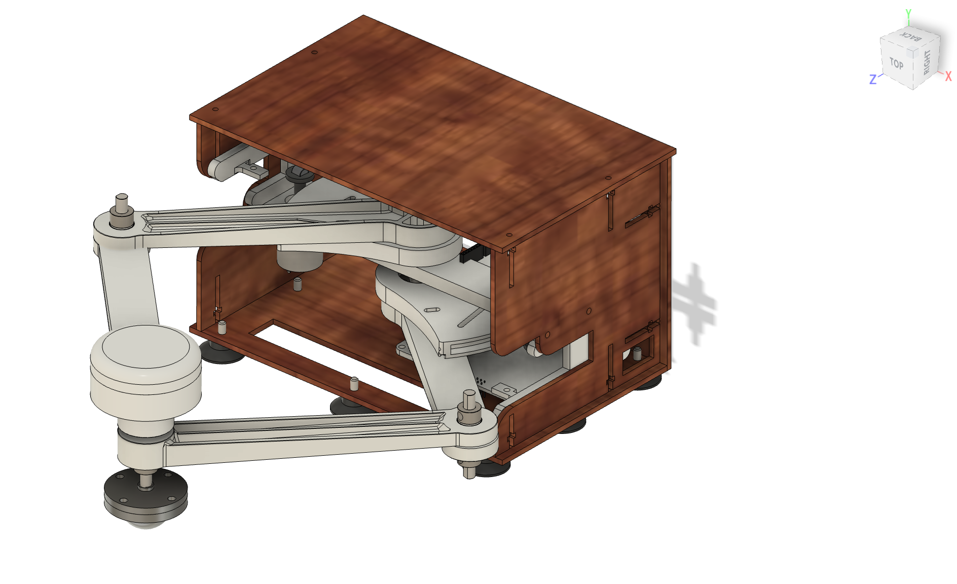

We also changed the attachment design from the sector to link 1 since the screw hub part used was discontinued. We instead opted for a more common flange shaft rigid coupler. We chose this replacement made of fine plating metal instead of 3D printing or removing this part since we want a strong even contact between the sector bore and the D shaft to allow "free space to feel free". We also want produce a more rigid connection between the linkage and sector part by putting the fastener through a rigid part rather than relying only putting fasteners through 3D printed parts directly.

In order to register when to release the puck in virtual space, we integrated a button on the end-effector puck. We cut a slot into the the puck design to house a limit switch, and ensure that the button is not too protruding or receded so that it is natural for the user to release the switch as they release the puck, and engage the switch as they hold the puck.


Haptic Feedback Implementation
1. Inertial Forces Rendering
To render inertial forces on the puck, we modeled the connection between the user's hand and the puck as a spring-damper system. This virtual coupling simulates the physical behavior of inertia through proxy dynamics.
We define:
- Spring force:
F_spring = k_m * (x_hand - x_proxy) - Damping force:
F_damping = -b_m * v_proxy
k_mis the stiffness constantb_mis the damping coefficientx_handis the current hand position (x, y)x_proxyis the proxy (virtual puck) position (x, y)v_proxyis the velocity of the proxy (v_x, v_y)
The total force acting on the proxy is the sum of spring and damping forces:
F_total = F_spring + F_damping
Using Newton�s second law, the acceleration of the proxy is computed as:
a_proxy = F_total / m
From the acceleration, we perform double integration using trapezoidal method to compute the next position of the proxy and update its motion.
The inertial force felt by the user is approximated using just the spring component:
F_user = k_m * (x_hand - x_proxy)
This ensures the haptic feedback feels like mass-related resistance during acceleration and deceleration, simulating realistic inertia through force rendering.
2. Wall Forces Rendering
To render wall forces to constrain the user from moving the puck out of bounds/ damaging the pantograph by extending past its limits, we first define the position of the far and side walls.
Wall positions:
- NWall (far wall):
NWall = 0.32 m - EWall (right wall):
EWall = 0.11 m - WWall (left wall):
WWall = -0.13 m
If the sides of the puck (determined by user position plus/minus radius of puck depending on exceeds the wall positions, we render wall force as a very stiff spring. For example for the far wall:
- Wall force:
Fx += 0Fy += -kWall * (NWall - (yh + rPuck))
kWallis the stiffness constantyhis the current hand position in y directionNWallis virtual far wall position in y directionrPuckis the radius of the puckFxis the wall force in x directionFyis the wall force in y direction
3. Friction Forces Rendering
To simulate friction, we combined both damping and Coulomb friction models. The resulting friction force is defined as a piecewise function:

This behavior, illustrated in the figure, is applied independently in both the x and y directions. We chose the transition threshold at ∣v∣=0.5 to ensure that when the mass starts from rest (v=0), it experiences a resistive force that prevents immediate motion. Within this threshold, the friction is proportional to velocity (viscous damping), while beyond it, the friction saturates at a constant value, representing Coulomb friction. This design ensures a realistic and smooth transition from static to dynamic friction.
Graphic with Unity
The 3D models of the shuffleboard table and puck were designed in Fusion 360 and imported into Unity. These assets were appropriately textured and scaled to fit the virtual environment. Unity�s built-in physics engine was utilized to simulate visually realistic interactions, including friction, collisions, and edge-fall behavior.
The game receives a string with five data from an Arduino Uno board over USB serial communication: �X-position, Y-position, Button state, X-velocity, Y-velocity�. A button state of 1 indicates that the user is holding down the physical button, which the system interprets as the user gripping the puck. During this phase, the virtual puck is actively controlled by the user, and all relevant force feedback effects�such as inertia, boundary force, and friction�are applied. To launch the puck, the user releases the button.
The system records the most recent velocity at the moment of release and applies it as an impulse force to the puck using Unity�s physics system. To simulate realistic sliding behavior, a friction force is applied continuously while the puck is in motion. The puck's physical properties include: Mass: 0.345 kg Dynamic friction coefficient: 0.8 A boundary detection function continuously monitors the puck�s position. If the puck travels beyond predefined board limits, gravity is enabled to simulate it falling off the edge. Collisions between pucks are managed using Unity�s Sphere Colliders and Continuous Collision Detection to ensure accurate responses, especially during high-speed interactions.
All physical parameters and launch force settings were carefully calibrated to create a natural and visually convincing experience.
System Analysis and Control
To render mass inertial effects to the user, we use a tight coupling of the virtual puck to the user end-effector. In order to select the k (spring stiffness) and b (damping coefficient), we used critically damped relationship:
b^2 = 4mk
We want the system to be critically damped so that it asymptotically approaches equilibrium as quickly as possible without oscillating[3]. We then tried different spring stiffness to determine the best "feel", balancing between the system feeling too "snappy" or too laggy.

We based our pantograph implementation on the work by G. Campion[1], utilizing a 2-DOF configuration derived from a 5-bar linkage, where one of the bars is of zero length. This design allowed us to formulate linear equations for computing the end-effector�s position directly from the magnetic sensor angle readings, significantly simplifying the real-time kinematic computations.
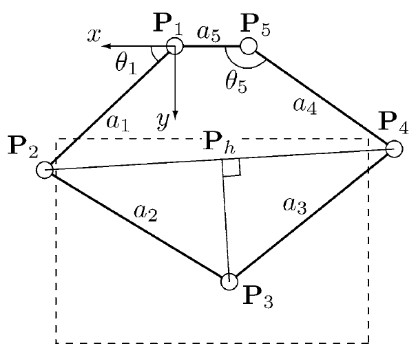
We find:

The end effector position P3(x3,y3) is then given by:

Demonstration / Application
To showcase the functionality and user experience of our system, we conducted a live demonstration of the VirtuSlide haptic shuffleboard, with a team member playing the game using the pantograph interface. The demonstration highlights the seamless integration of hardware, physics-based modeling, and haptic rendering that allows the user to physically feel the motion of the puck as it slides, slows down due to friction, and bounces off virtual boundaries. As shown in the accompanying video, the user can grip the puck via the end-effector, launch it with a flicking motion, and receive force feedback that reflects collisions, surface texture, and inertial resistance in real time.
The system translates the user's physical motion into virtual puck dynamics within Unity, offering visual feedback synchronized with tactile sensations. When the puck contacts the edges of the shuffleboard, users feel distinct resistance that simulates hitting a wall. Similarly, as the puck slows due to frictional forces, the user experiences subtle resistance through the pantograph handle�adding realism and making gameplay feel intuitive and physically grounded. The demonstration also reveals the effectiveness of our mass rendering model, which allows users to perceive momentum changes even in the absence of a real puck.
Overall, the application demonstrates how haptic feedback can dramatically enhance virtual interactions. By blending kinesthetic input with physics-based simulation and visual rendering, VirtuSlide offers an immersive experience that goes beyond traditional screen-based games. This prototype paves the way for future interactive entertainment, training simulators, and rehabilitation tools where realistic touch and motion feedback are essential. The demonstration confirms that even with a relatively simple setup, rich and responsive haptic experiences are achievable. Attach:sbvid.mov
Results
We collected some feedback from the users on the haptics and game experience. Most people found the game realistic and are able to feel the virtual boundaries of the game field from the force feedback.


There are more mixed responses on whether they can feel the rendering of the puck mass. However, we noticed that in times where we asked the users to compare the "feel" of the puck before and after engaging the haptics inertial effects, they are able to tell the difference. This shows that our system does give a moderate inertial effect, but the effect is sometimes overshadowed by the ball caster at the end-effector. In addition, we have debated whether to increase the inertial effects by scaling up the virtual mass to ~1kg (vs actual mass ~0.35kg) and it significantly hindered the gaming experience since it creates so much resistance. Therefore, we decided to scale back the effect to be large enough to be felt subconsciously, but not too large to make the game unplayable.

Future Work
To improve the accuracy and robustness of the system, one major area of development lies in enhancing the position tracking mechanism. While the current system uses potentiometer-based sensing via the Hapkit board, it requires frequent recalibration and suffers from minor drift. Integrating rotary encoders would provide more precise and reliable angular measurements, thereby reducing cumulative error over time. Additionally, refining the position-to-screen mapping algorithm would enable more accurate alignment between the physical device and the virtual environment, leading to a smoother and more intuitive user experience. These changes would significantly improve gameplay precision and reduce the maintenance overhead for users and developers alike.
Another avenue for future development involves expanding the user interaction and visual immersion of the virtual shuffleboard game. Adding interactive UI features, such as allowing users to click to spawn a new puck or reset the game, would streamline the gameplay loop. Furthermore, incorporating AI opponents or multiplayer modes would enable more dynamic interactions, supporting both competitive and cooperative play. This would elevate the platform from a single-user demonstration tool to a more complete haptic gaming experience, offering broader engagement and potential educational applications.
Lastly, considerations for mass manufacturability and improved design robustness are essential for scaling the system beyond a research prototype. This includes optimizing the mechanical assembly, using more standardized components, and simplifying the wiring layout to reduce build complexity. Replacing the current physical limit switch with a phototransistor could improve signal consistency and eliminate mechanical wear points. Smoothing the surface of the puck and enhancing its ergonomic feel would also improve the overall user experience. Together, these enhancements would pave the way toward a cost-effective, scalable, and user-friendly haptic gaming platform.
Acknowledgments
We would like to express our sincere gratitude to the teaching staff for their guidance and support throughout the course. We extend special thanks to Professor Okamura for suggesting the virtual coupling approach for rendering inertia, which significantly enhanced our project. We also appreciate the assistance of CAs Ryan and Teo, whose help with debugging was invaluable. Finally, we thank ME 327 (2023) Group 1 for providing an excellent design foundation on which we were able to build.
Files
Arduino code: Attach:shuffleboardArduino.txt
Laser Cut Housing: refer to ME 327 2023 Group 1
References
[1] Campion, G. (2005). The Pantograph Mk-II: A Haptic Instrument. In: The Synthesis of Three Dimensional Haptic Textures: Geometry, Control, and Psychophysics. Springer Series on Touch and Haptic Systems. Springer, London. https://doi.org/10.1007/978-0-85729-576-7_3
[2] Dai, C., & Matsumaru, T. (2015). "Simulating and displaying of puck motion in virtual air hockey based on projective interface," 2015 IEEE International Conference on Robotics and Biomimetics (ROBIO), Zhuhai, China, pp. 320�325. doi: 10.1109/ROBIO.2015.7418787.
[3] LibreTexts, Physics. "Damped Oscillations". University Physics I � Mechanics, Sound, Oscillations, and Waves (OpenStax). https://phys.libretexts.org/Bookshelves/University_Physics/University_Physics_(OpenStax)/Book%3A_University_Physics_I_-_Mechanics_Sound_Oscillations_and_Waves_(OpenStax)/15%3A_Oscillations/15.06%3A_Damped_Oscillations#:~:text=Many%20systems%20are%20underdamped%2C%20and,as%20in%20curve%20(b).
[4] Ruspini, D. C., Kolarov, K., & Khatib, O. (1997). The haptic display of complex graphical environments. In SIGGRAPH '97: Proceedings of the 24th annual conference on Computer graphics and interactive techniques (pp. 345�352). https://doi.org/10.1145/258734.258878
Appendix: Project Checkpoints
Checkpoint 1
Our checkpoint goals are as follow:
- 1. Finalize CAD of design system.
- 2. Order hardware components if needed. Manufacture finalized parts.
- 3. Research how to create visualization on Unity.
- 4. Create initial pantograph end-effector tracking code with kinematic equations.
Here are the goals that we have met:
- Finalize CAD of design system.
- Order hardware components if needed. Manufacture finalized parts.

- Visualization on Unity
I watched tutorials on how to implement physics in Unity. As a starting point, I am planning a simple test involving a 3D shuffleboard and puck designed in Fusion 360, with interaction via the mouse pointer. This week, I completed the 3D model of the shuffleboard in Fusion 360 and successfully imported it into Unity. However, the material settings did not transfer correctly during the import process.

- Create initial pantograph end-effector tracking code with kinematic equations
According to the paper by G. Campion[1], The Pantograph Mk-II: a haptic instrument, the model of the kinematics used to compute the direct problem can be illustrate as:
We find:
The end effector position P3(x3,y3) is then given by:
After differentiating the kinematic equations with respect to θ1 and θ5, we get:

The arduino code is Attach:ckpt1.txt.
Checkpoint 2
Our checkpoint goals are as follow:
- 1. Assembly of pantograph
- 2. Be able to track position of pantograph end effector accurately
- 3. Link end effector position to virtual position accurately.
- 4. Implement force outputs in correct magnitude and direction
- 5 Graphic- Unity Implementation with Mouse Control
Here are the goals that we have met:
- 1 Assembly of pantograph
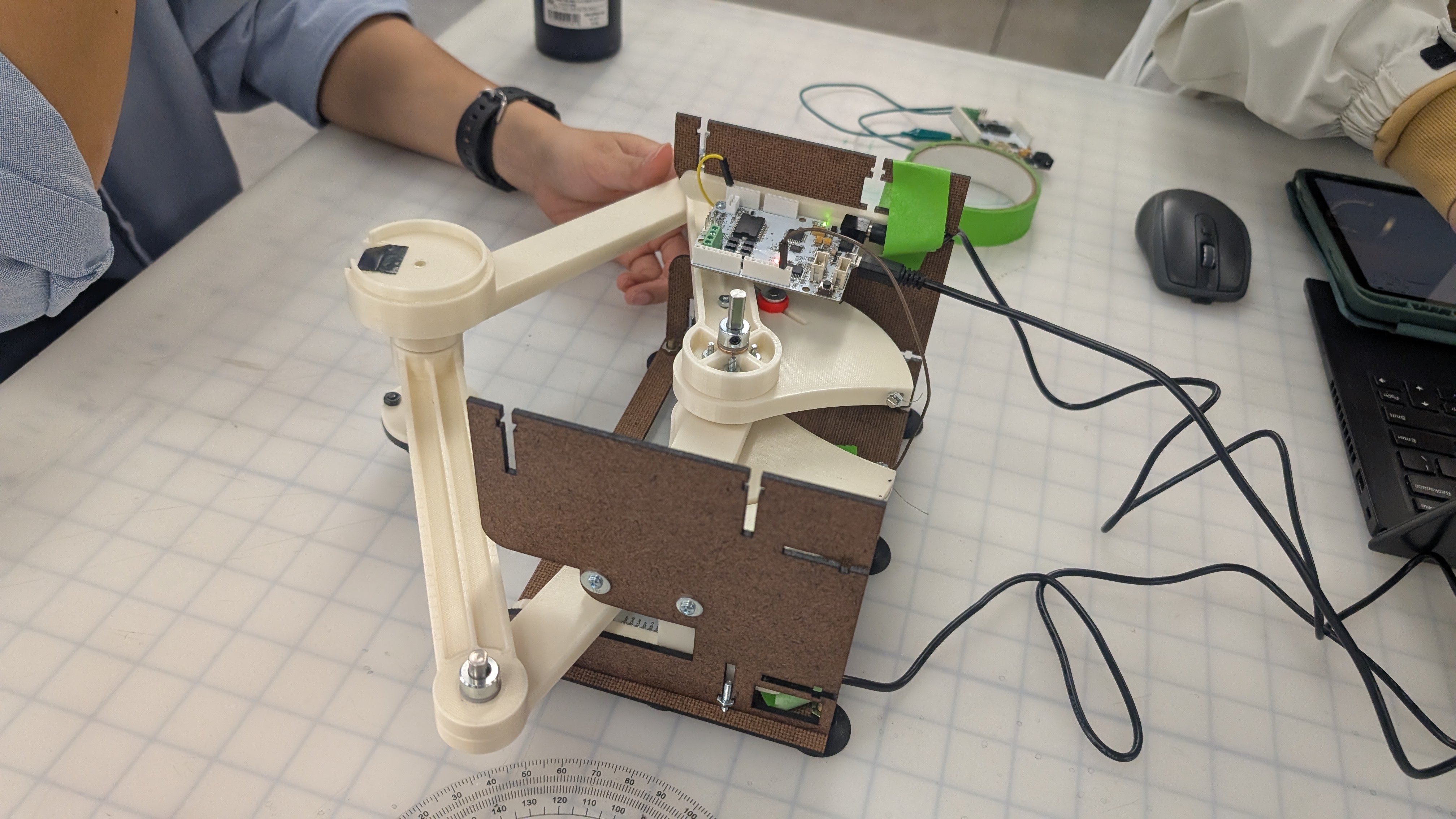
We have not fully assembled the laser cut enclosure to allow for easier access to the boards during debugging and electronics integration. Here is a video of the pantograph range https://drive.google.com/file/d/1AndhvP28gCZ6JidAXklCB3XExU5HUEHy/view?usp=sharing
- 2 Be able to track position of pantograph end effector accurately
We successfully implemented two key components: obtaining the joint angles (θ₁ and θ₅), and using kinematic equations to compute the end-effector position. After calibration, the position tracking proved to be accurate. Below is a sketch illustrating how we convert the measured angles into θ₁ and θ₅:

<<<<<<<
- 3 Link end effector position to virtual position accurately
https://drive.google.com/file/d/1OsIE5mn2m5TJahmnTEXODmviF7hWxVuV/view?usp=sharing
Here we visualized the position of the end-effector in processing. The next step will be to input the position to unity, where we will do the actual visualization
- 5 Graphic- Unity Implementation with Mouse Control
We successfully implemented a shuffleboard game in Unity with turn-based mechanics and scoring rules. Each team has three chances to throw their puck, and scores are calculated at the end of all rounds based on final puck positions. As the next step, we plan to replace mouse input with the physical x and y position of a real-world puck, and map that input to the virtual board.
Here we recorded a video of 1 example round of game. https://www.youtube.com/watch?v=c6RBVFmPa-A&feature=youtu.be
Here is the link to the Github: https://github.com/zinyamintun/ME327_ShuffleboardGame.git
However, we were unable to complete the final force output due to two main reasons:
- 1. The time required to properly calibrate system exceeded our initial estimates.
- 2. We still need to determine a safe way to implement inertia.
We underestimated the amount of time needed for communication between the two Hapkits and for calibration. For communication, our original plan was to use Tx/Rx: one board would transmit sensor data as the "leader," and the other would receive it as the "follower." We created a SoftwareSerial object on the leader board and spent time figuring out which pin to use for output. After setting up the leader and follower code, we first tested whether data could be transmitted. Once confirmed, we merged the follower code into our main Arduino program.
However, we ran into calibration issues due to unexpected jumps in updatedPos. During office hours, we learned that we could treat the leader board simply as a sensor by connecting its MR sensor output pin to an analog input on the main board, and grounding the two boards together. This approach significantly simplified communication. Through this process, we gained valuable insights into SoftwareSerial, inter-board communication, and some specific properties of the Hapkit. For calibration, the most important lesson we learned was the importance of consistently defining where to reset and begin measuring. Otherwise, the zero position would vary with each trial.