

2025-Group 6


Ankle Flexion Rehabilitation Haptic Feedback Device
Max Burns, Mattias Cooper, Andrew Zerbe, Andrew Zaman
Lower-limb injuries, such as to the ankle, often require manual physical therapy. Although effective, therapy is resource-intensive and not always accessible. To address this gap, we developed a device that provides corrective haptic feedback through vibration and skin stretch, allowing patients to perform exercises at home under remote guidance. Our device uses a 3D-printed frame, twelve vibration motors, and a servo motor. It is controlled by a microcontroller and custom off-board software incorporating real-time angle measurement via computer vision. We implemented proportional and frequency-based patterns to indicate target ankle angles, and built a range-of-motion exploration game. At an open house, users demonstrated reliable interaction with the system. This prototype demonstrates the feasibility of using haptics for delivering proprioceptive cues to the lower limb. We hope parts of the project can be integrated into more complex applications such as exoskeleton training.
On this page... (hide)
Introduction
Ankle injuries are a common form of lower body injury that require rehabilitation. Inversion ankle sprains alone have an incidence rate of seven injuries in every 1000 people. There are currently two forms of rehabilitation for ankle injuries. The first method is manual therapy and exercise (MTEX) done by a physical therapist (PT), where a PT manually manipulates the ankle joint through a range of motion. The second method is home exercise programs (HEP) supervised by physical therapists through regular check-ups but performed largely by patients at home by themselves. Previous studies have found that patients rehabilitated with MTEX experience statistically significant greater improvement in the Foot and Ankle Ability Measure activities of daily living scale, both at four weeks and six month follow-ups. They also experience less pain than the HEP group at both time periods (Cleland et al., 2013).
Our aim is to create a device that guides patients through strengthening exercises at home that a physical therapist can prescribe remotely. Haptic feedback is an intuitive feedback mechanism for this use case because it leverages the body's natural ability to sense skin and muscle stretch as a joint works through its range of motion. By leveraging the body�s natural feedback mechanism, we predict a patient is able to rehabilitate the muscles and tendons to actuate the joint more quickly by also strengthening the neuromuscular connection.
Background
Previous devices have incorporated vibrations to cue individuals to flex their ankle during gait, especially with chronic stroke patients (Park et. al., 2015). Vibrating specific muscle segments improved ankle flexion in stroke patients exhibiting foot drop during their gait (Paolini et. al, 2010), and a similar device used six vibratory motors in an elastic band just below the knee to deliver haptic feedback to unilateral hemiparetic stroke patients (Afzal et. al, 2018). Additional devices have been developed employing skin-stretch to provide proprioceptive information or haptic feedback. Unlike vibrotactile feedback, skin stretch has the possibility to convey very noticeable and analog information without short-term desensitization (Bark et. al., 2010). Since skin mechanoreceptors contribute substantially to proprioception, skin stretch is especially suited for tasks where it can provide proprioceptive feedback because it more closely matches the tactile sensations of moving a biological limb than vibrotactile feedback (Edin et. al., 2001). Skin stretch has been shown to provide more granular feedback, especially regarding relative position and rate of change (Y.-T. Pan et. al., 2017). The authors also show a reduction in oscillatory behavior around setpoints when skin stretch is added to visual feedback. Such devices do not typically rely on creating an illusion of limb motion where there is none, but the closer match to real sensations leads to easier mental mapping for the participant, which can reduce cognitive load and improve task performance (Bark et. al., 2008).
Methods
Hardware Design
Frame
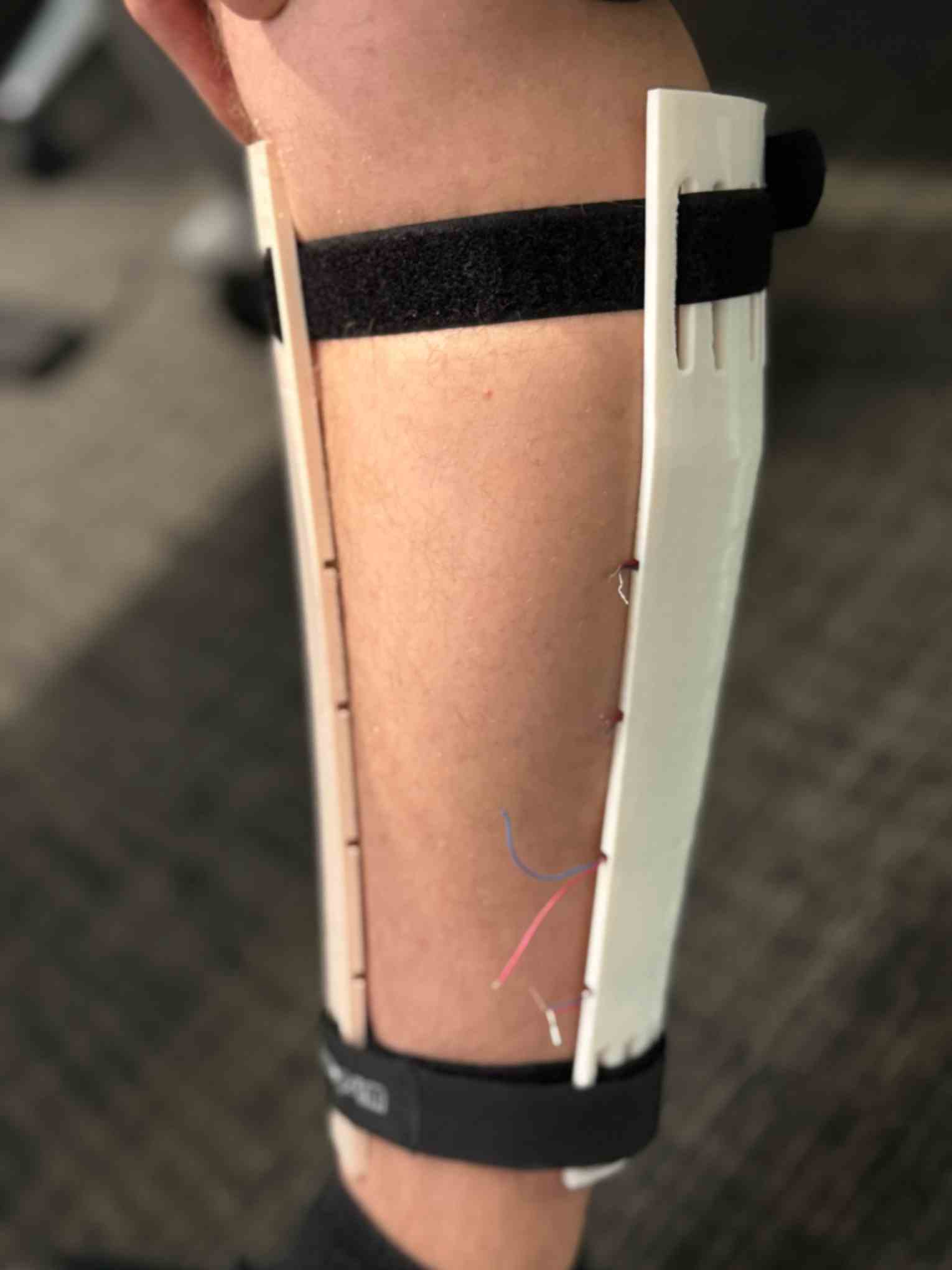
The frame consists of three struts, one of which is pressed against the calf, the other against the medial part of the shin, and the last against the lateral part of the shin. The struts are connected together by three velcro straps, which are tightened around the lower leg of a user just below the knee, half way down the lower leg, and just above the ankle.

The back of the rehabilitation device, showing the location
of the straps and microcontroller.

The front of the rehabilitation device, showing the location
of the vibration motor array and the skin-stretch servo.
Vibration Motor Array

The front of the strut
for the calf.

The front of the strut
for the medial shin.
Previous work determined that two-point discrimination for men and women along the lower leg was between 37.7 - 43.6 millimeters (Nolan, 1983). Therefore, motors on both struts were spaced out by 38 millimeters.
The strut pressed against the calf had an array of four pairs of vibration motors, wired in series. Each pair was wired to ground and a separate digital pin. This strut was initially framed by three concentric semicircles, running longitudinally, comfortably fit around the calf muscle. The circumference of these semicircles were initially measured just below the knee, around the largest part of the calf, and just above the ankle of a 5�11� adult male. Subsequent iterations reduced the circumference and longitudinal distance between each semi-circle to comfortably fit a 5�8� female. Further prototyping adjusted these measurements for a strut that could comfortably fit on most female and male calves.
The strut pressed against the medial part of the shin had an array of four single vibration motors. Each motor was wired to ground and a separate digital pin. This strut had a rectangular frame but was bent along a 10 degree arc to follow the natural convexity of the medial shin. The length of the strut was adjusted on each iteration to match the length of the calf strut.
Both struts were printed out of thermoplastic polyurethane (TPU) for increased user comfort and to dampen vibrations throughout the frame. Along with extruded cuts for motor placement, there were extruded cuts incorporated to embed wires within the frame to prevent friction of the wires against a user.
Skin-stretch Servo

The skin stretch servo, wheel, and frame.
The skin stretch system was heavily inspired by Bark et. al., 2010. The paper demonstrates a device that rotates two 20mm-spaced silicone pads along an axis normal to the surface of the skin. As a proof-of-concept, we performed some pilot testing, comparing linear skin-stretch along the limb axis to rotational skin-stretch as in the paper. Despite linear skin-stretch being possibly more accurate to the proprioceptive feelings of typical joint movement, our participant, who had her eyes closed and was not informed about the experimental purpose, responded more quickly and accurately to the rotational stimulation and preferred the sensation. This is corroborated by a line in the paper as well.
The paper lists torque, angle, and weight specifications for their device: 0.6Nm, 15-150 deg/s, and 150g, with 0.05deg resolution. The authors selected a piezoelectric motor to avoid the sensation of motor vibration; we used a coreless-motor hobby servo intended for steering RC drift cars, which meant it was designed to be fast and accurate with much less vibration than a typical hobby servo motor. The SP-02D motor we selected has a stall torque of 0.98Nm at 5V, can rotate at 645 deg/s, and weighs 50g, albeit with substantially lower real-world accuracy than 0.05deg. Participants in the study were only able to discriminate angles greater than 2-5 degrees, making the reduced accuracy a reasonable trade-off for power density and mechanical simplicity.
The interface between the servo and the skin is an RC car wheel intended for drag racing, giving it a soft rubber surface that grips the skin in a 25mm ID, 38mm OD ring. In the 2010 paper, the device rotated a disk with two discrete 14mm rubber pads spaced 26mm apart, each of which were attached to the participant with skin-safe adhesive tape. Since our device relied solely on static friction, the servo could slip on the skin, which would result in a neutral servo position that did not correspond to an absence of skin stretch. It is also not obvious whether the disk contact surface leads to higher or lower skin strain energy density compared to the two discrete points.
Wiring to the Hapkit Board

Wiring diagram. Not depicted is the prototyping shield,
which enables the grounds to be more spread out into
separate pins.
There are four pairs of motors wired in series, which correspond to the four pairs of motors that were on the calf strut. Each pair was wired to a separate digital pin and ground. Compared to a parallel wiring arrangement, series wiring resulted in reduced power output due to the effective voltage divider. However, it ensured that the motors always operated safely within their nominal voltage range, and that the current draw on each digital pin was reduced compared to parallel wiring, preventing brownouts or damage to the microcontroller.The four individual motors, each wired to a ground and digital pin, correspond to the motors on the medial shin strut. Motors depicted towards the top of the wiring diagram were embedded in the strut closer to the knee, and motors depicted towards the bottom of the wiring diagram were embedded in the strut closer to the ankle.
The servo is wired to a digital pin, ground, and 5V VIN source, which is capable of up to 1A. An arduino uno prototyping shield was used to increase the number of ground pins, and the four grounds from the individual motors are connected to a common ground pin, which can be seen in the pictures showing the device as assembled in the �Frame� subsection.
Software Design
Commands to the Microcontroller
The Hapkit board only has six digital pins capable of pulse-width modulation (PWM), but the device design has eight independently controlled motor units (four individual and four pairs). To work around this limitation, our design takes advantage of a quick loop rate on the Hapkit board to create a custom duty cycle, which creates a software PWM for each digital pin. To achieve this fast loop rate, we compute all commands in a Python script on a laptop and then only send a byte array of commands to the board via serial communication. By offloading the computation, we can take advantage of the superior processing power of a standard laptop and keep the cycle time to a minimum for the board. This method has the added advantage of only requiring one flash of the control board (the initial upload that parses the commands coming from the laptop), allowing for rapid code adjustment for prototyping. The major drawback of this method is that it requires our device to remain wired to the computer, but we determined that to be a sufficient tradeoff during this early prototype to characterize what feedback is sufficient to train ankle rehabilitation.
Computer Vision for Measuring Ankle Angle

Computer output showing each step to isolate the markers.
By taking advantage of the additional power on a laptop, we can use computer vision to track the ankle angle of the user. Our script uses OpenCV, an open-source computer vision library, to mask colors based on their hue-saturation-value (HSV). We isolate red stickers with an HSV mask, and then erode and dilate the mask to improve robustness to noise. Then, a Hough circle transform is used on the resulting mask to extract circles as center-radius pairs to get the coordinates of four points - two along the shank and two along the foot. Built-in logic uses the distances between points to determine the body segment to which each point is attached. Then, these four points are used to create two lines representative of the foot and shank, and the angle between these two lines is used to approximate the ankle angle.

Live display showing real-time ankle angle.
Feedback Modes
There are four different feedback modes. Two of these modes provide feedback to get the user to find an ankle angle setpoint. The remaining two modes are a rehabilitation game that encourages a user to explore his or her ankle range of motion.
Proportional Control of Servo and Vibration Motor Array
The first feedback mode uses proportional control of the servo and vibration motor array to help a user find an ankle angle set point. It does this by finding the error between the user�s current ankle angle and the set point and then uses a proportional gain to increase the amplitude of the vibration motors and increase the angle of the servo (which increases the amount of skin stretch). If a user is plantarflexed (toe pointing away from his or her body) beyond the set point, the motors on the shin vibrate and the servo turns counterclockwise. If a user is dorsiflexed (toe pointing towards his or her body) beyond the set point, the motors on the calf vibrate and the servo turns counterclockwise.
Frequency Control of Vibration Motor Array
The second feedback mode uses both sides of the vibration motor array to signal whether a user is getting closer or farther from the desired ankle set point. The manually controlled duty cycle (see �Computer Vision for Measuring Ankle Angle� section) is modified based on the error between current ankle angle and desired ankle angle. If the user is getting farther away, the length of time the motors are on and off decreases (increasing the overall frequency of stimulation). If the user is getting closer, the length of the time the motors are on and off increases (decreasing the overall frequency of stimulation). Once the user is within a certain error range, stimulation is disabled.
Range of Motion Expansion Games
The third and fourth feedback modes are two different forms of haptic feedback to encourage a user to explore his or her ankle flexion range of motion. The first form of haptic feedback is two short pulses of the vibration motor array. The second form of haptic feedback is two short turns of the skin-stretch servo. During both forms of stimulation, the user begins at a neutral set point (about 110 degrees). If she plantarflexes by five degrees to an ankle angle of 115 degrees, she will feel haptic feedback. This feedback indicates the user should begin dorsiflexing until she reaches 105 degrees, at which point she will receive feedback again. The user will continue reversing direction as the point for feedback expands further and further apart, until she reaches a point of maximum flexion.
System Analysis and Control
Control of the haptic device was designed for low-latency, and on-device computations and memory usage were kept to an absolute minimum due to the constraints of the Hapkit board. The device continuously read information from a serial buffer, and used start/end bytes to designate when to accumulate and then send a command to the actuators. A 9600 baud rate was used, with 12 bytes containing each command. This allowed a maximum control frequency of 100 hz (9600 bits per second = 1200 bytes per second). Practically, this significantly exceeds the needed control frequency, so 40 hz was used for control. As explained above, software PWM was used for four of the eight vibration motors, which used a virtual duty cycle imitating hardware PWM.
Ankle angle was sampled using computer vision at 40hz, as described above. Ankle angle was stored in a 0.5 second buffer and filtered using a 10hz low-pass filter before it was used to compute new commands. This stabilized the ankle angle readings enough to provide low noise when using proportional error feedback.
It was observed that vibration motors and the servo required time to reach steady state due to their inertia. If on/off commands were sent rapidly, the stimulation was perceived to be weaker, and therefore less useful to the user. We used limits of 10hz for on/off switching behaviors, which allowed enough time for the motors to cyclically reach steady state and then slow down.
Directional feedback was difficult to interpret, so when random goal angles (unknown to user) were supplied and a user was asked to find them, exploratory behavior was observed. We hypothesise that this is used to establish a sense of the feedback gradient (i.e. plantarflexion increases feedback, therefore it is best to change direction) so that the goal can be found. See the figure below for an example of random goal-seeking behavior; it is clear that the user overshoots repeatedly while building an understanding of the goal.

Rise and settling times varied due to the lack of clear directional feedback, but in the above example we estimated a rise time of 1.5s, and a settling time of approximately 1s. The steady state error is within +/- 2.5 degrees, which corresponds to the programmed deadband.
Miscellaneous Design and Implementation Decisions
While prototyping, there were several key findings that influenced the final design and implementation. We found that the haptic feedback was stronger and more consistent on a relaxed limb as compared to a flexed limb. Therefore, we elected to have the feedback device mounted on the right leg while the left ankle worked through the range of motion. Despite the feedback being on the contralateral limb, the human-in-the-loop control remained intuitive for users.
We tried implementing several different control modes that did not ultimately provide effective haptic feedback. Most interestingly was a saltation effect we attempted to try to create a shearing effect on the limb. The intended effect was to have motors turn on and off in sequence up the anterior side of the leg and down the posterior side of the leg (or vice versa) depending on whether the user was supposed to dorsiflex or plantarflex. However, we found that it was difficult to differentiate between individual motors on either side of the leg. We have two hypotheses as to why this may have occurred. The first is that the entire strut vibrates too much, so the user just feels the whole strut vibrating as opposed to the individual motor. The other is that the proximity of the shin strut to the tibia, with very little soft tissue in between, interacts with the pacinian corpuscles in the skin differently than when the vibrations are on the calf, which has much more soft tissue between the device and the posterior part of the tibia.
Results
Qualitative impressions of the device at the open house were largely positive. The sensations were even described as �magic� to reach a setpoint. Participants were especially engaged with the range of motion tasks, which provided a challenge with clear parameters, and the haptic feedback was instantaneous and clear enough to be consistently legible. Some participants interpreted proportional feedback with relative success, getting within 5-10 degrees of the set point, while others struggled to distinguish the zero-feedback setpoint from other ankle angles that were providing constant vibration and stretch. For the proportional feedback, some enjoyed the mixture of feedback types as it made honing in on the setpoint faster and more intuitive, while others commented on increased cognitive load. This difference could be due to inter-subject variability in sensitivity, or inconsistency of our donning procedure, particularly in the rotational location of the device along the axis of the leg and the tightness of the straps. It is also possible that further verbal explanation could clarify for participants how the stimulation is mapped to angle error.

Quantitatively, the above plots correspond to different testing modes where a user�s eyes were closed for all trials, goals were generated randomly all within the same range, and there was no way of knowing what the goal was besides feedback. The goal would reset once the participant entered the deadband range around the goal for a few seconds. These plots show the exploration strategy of the user while interpreting the feedback. For instance, around 30 seconds for the vibration frequency feedback (bottom right), there was an initial exploration close to the goal, which was not attained as the position was not maintained long enough. The user then goes to the furthest position in the other direction where the feedback indicates being far from the target. Only after this back and forth exploration, does the user conclude the setpoint is at the other extreme. A similar phenomenon can be observed around 60 seconds in the proportional vibration feedback (top right). This leads to significantly higher settling times. The steady-state error is within the limit of the deadband (+/- 2.5 degrees), and it ranges between being very close to the actual target and being at the limit. For the expanding range of motion rehabilitation game (bottom left), the expansion of the goal is clearly visible, and the decrease in the frequency after 30 seconds corresponds to the user stretching to reach the limits of his range of motion.
Overall, for the different modes, the results are:
Vibration frequency control: 20 goals in 135s, 6.75 s/goal
Vibration proportional control: 20 goals in 100s, 5 s/goal
Vibration and servo proportional control: 33 goals in 200s, 6.06 s/goal
This user has the best performance and appears to be most comfortable with vibration proportional control.
Future Work
Design Modifications
There are several opportunities for an improved design. The skin stretch communicated signals very effectively, so a future design may incorporate an additional servo to provide increased control and feedback methods. It was difficult to distinguish between individual vibration motors, both for vibration motors on the same side of the leg, and even vibration motors on opposing sides. These could be replaced with either higher power motors or even voice coils to provide more clear signals. Moreover, redesigning the frame to better isolate the vibrations of each motor may be important to provide discrete feedback with each individual motor.
Redesigning the frame to implement a proper angle encoder would eliminate the need for computer vision to get the user�s current ankle angle. Moreover, using a different microcontroller (such as a PJRC Teensy or Arduino Mega) would provide more PWM pins and compute power, which would eliminate the need to maintain a wired connection to an off-board computer.
The device doesn�t provide feedback on the ankle position in the user�s range of motion, it mostly indicates where the ankle should go. One could imagine giving feedback integrating a mode to give this proprioceptive information to the wearer based on which vibration motors are being actuated. Finally, for the computer vision part of the project, we used a mask to determine the location of colored stickers on the individual. Given the rise of deep learning for computer vision, models that will detect the angle of the ankle based on existing biomechanics vision software could facilitate the use of such a setup.
Further Testing and Experimentation
Further testing is necessary to refine the feedback to reduce settling time and steady state-error. Determining a feedback mode that provides a more intuitive sense of how far away a user is from the target would increase reaction times as users can commit to much larger movements early before settling. Experimenting in more dynamic situations, such as with a user walking, would also provide insight as to feedback modes that work better or worse when muscles are activated and tense.
Applications
Refinement of the feedback technique may be sufficient to fulfill the proposed use case of a simple, 1-DOF ankle rehabilitation device where patients are empowered to practice strengthening exercises at home that a physical therapist can prescribe remotely. Because participants generally moved their joints as the device prompted, particularly in the range-of-motion test, this device could provide more detailed and immediate feedback than verbal coaching alone in a telehealth context.
There are many applications for this device as it is able to communicate to the user the rotational position of their limb in real time to either reach goals and to know when to stop moving the ankle.
One main application in which we hope to integrate some elements of this design are for lower limb exoskeletons. In existing exoskeleton studies, the user is typically not guided or coached, other than to �walk how it feels most [natural/good]�, which can lengthen adaptation times as users get trapped in local minima and are hesitant to explore the substantive variations in gait pattern that are necessary for optimal energy efficiency. Visual biofeedback has shown promise to more swiftly guide users towards known-efficient gait patterns. However, it requires the participant to be watching a screen providing feedback at all times, and it requires substantial cognitive effort to translate visual abstractions (arrows, graphs, etc.) to the desired joint kinematics changes. Haptics could provide valuable feedback to a user because tactile/kinesthetic feedback from a device placed on or near the joint of interest is much more closely related to the tactile and proprioceptive sensation of walking. We theorize this will provide an easier mental mapping exercise for new exoskeleton walkers.
Similarly, users of prosthetic limbs often struggle with understanding the movement of the prosthesis as they have no direct proprioceptive sensing, only tactile sensing of reaction forces through the socket on their residual limb. Embedded sensors at the joints of the lower limb could relay valuable force/position information through the haptic device. This could be used first while the user is standing still, gaining more and more intuition about the range of motion and setpoints that are attainable. Later, it could aid the users to regain a more steady gait to both reduce fall risk and improve energy efficiency. As such, a device like this has both a rehabilitative and assistive capacity.
Regarding fitness applications, this could be used to help users stretch by logging previously achieved ankle angles, set a time and amplitude goal, and hold the stretch for a period of time. The haptic feedback would indicate to the user when he or she has reached the desired ankle angle. Moreover, the device could indicate proper joint angle during a complex, compound lift (squat, deadlift, lunge). Certain exercises have mechanically favorable loading of joints, and haptic biofeedback would provide a means to alert a user to when he or she needs to make modifications in his or her form. Furthermore, the skin-stretch could inform a user on limits of their range of motion for a set exercise to not go past a safe threshold.
Files
Code, design files, and a bill of materials can be found at https://github.com/maxjburns/HapticRehab/. The design files and bill of materials are located under the design_files folder. The code for the calibration of the computer vision, data visualization, and main python functions are found under the utils folder. Data for controls analysis can be found in the data folder.
References
Appendix: Project Checkpoints
Checkpoint 1
1. Developed an openpose wrapper. The wrapper uses a normal webcam to video capture an ankle flexing and extending, automatically determines the foot and lower limb segments, and then prints the ankle angle in degrees at about 12 Hz. We will send this ankle angle over the serial to the microcontroller. https://youtu.be/-VPuYHxD2MU
2. Prototyped skin-stretch. We bought a low-profile servo with torque specs matching prior literature, and mounted a few types of grippy wheels (intended for RC dragsters) to twist/roll the skin. On an uninformed pilot participant, we tested feedback with the plane of the wheel flat on the side of the leg, and with the track of the wheel on the calf of the leg. Surprisingly, the plane of the wheel flat on the leg provided clearer feedback to our participant (like some of Prof. Cutkosky�s work: https://ieeexplore.ieee.org/abstract/document/5453369). We built a frame to mount the servo, which needs some testing, and we need to find an easier way of actuating it than a 2010-era control board with Windows-only software. Video link: https://youtu.be/1-VnrEfC07M
3. Prototyped a rigid, three strut brace that can hold up to 16 coin vibration motors that can be mounted to the calf and shins with velcro straps. We still need to complete the wiring of all the motors (we ordered an additional 15 motors), but once complete, we can experiment with different vibration patterns and intensities to communicate information to the user (saltation effect, pulses, etc).
4. We decided to keep developing both vibration and skin-stretch, and hope to integrate both on our full system. This will allow us to compare the methods individually, and hopefully develop an even more effective sensation combining the two. (There is some precedent for this: https://ieeexplore.ieee.org/abstract/document/10309652)
5. We decided to stick with rigid frames, attached to the body with velcro straps�a fully soft method would be out of the scope of this project.


Checkpoint 2
Here you will write a few paragraphs about what you accomplished in the project so far. Include the checkpoint goals and describe which goals were met (and how), which were not (what were the challenges?), and any change of plans for the project based on what you learned. Include images and/or drawings where appropriate.
1. Arduino code was written and flashed to handle the commands of the python code linked to openpose.


2. We 3D printed an updated prototype in TPU with a casing for the boards and lodgings for the vibration motors wires. The wiring of all motors is complete on both the calf and shin braces. This included soldering 2 motors in series for each of the 4 rows of the calf brace. Each row of motors can be independently controlled by the python code for both the calf (4 rows of 2 motors) and the shin (4 rows of 1 motor).
3. This week we finished the software communication structure. All computation is done in python, which includes OpenPose estimation of the ankle joint angle, decisions about the feedback to provide, and the commands sent to the Arduino. Commands are sent as byte arrays with the following convention: [START, FEEDBACK_MODE, SERVO_ANGLE, VIBRATION_DUTY_CYCLE_1, VIBRATION_DUTY_CYCLE_2, ... END] This is used to minimize the amount of computation conducted on the Arduino due to the limited clock speed. We also modified the Arduino code to support software PWM, which does not rely on the three internal PWM timers typically used for PWM control (an Arduino Uno can only support six hardware PWM pins, but we needed eight + servo). Duty cycles are transmitted from python, and a loop is used to command the digital control pin low or high at the appropriate switching frequency.
Python is used for all control and decision-making. Commands are added to a queue which is executed at a set frequency. This allows the addition of time-based saltation effects (many commands are added to queue at once) and direct feedback control (one command is added each timestep). A demonstration which uses this structure for live feedback control is available at the following link: https://youtu.be/5JEda6s8YWk
4. We also continued our literature review and found some papers to help guide various control techniques for our haptic device:
Vibrating muscles responsible for movement can serve as a cue for a patient to flex their ankle during gait (Park, J. M., Lim, H. S., & Song, C. H. (2015). The effect of external cues with vibratory stimulation on spatiotemporal gait parameters in chronic stroke patients. Journal of physical therapy science, 27(2), 377-381).
Addition segmental muscle vibration may improve gain performance in patients suffering from foot drop after a stroke (Paoloni, M., Mangone, M., Scettri, P., Procaccianti, R., Cometa, A., & Santilli, V. (2010). Segmental muscle vibration improves walking in chronic stroke patients with foot drop: a randomized controlled trial. Neurorehabilitation and neural repair, 24(3), 254-262).
A similar device has been made that has six vibratory motors in an elastic band just below the knee (Afzal, M. R., Pyo, S., Oh, M. K., Park, Y. S., & Yoon, J. (2018). Evaluating the effects of delivering integrated kinesthetic and tactile cues to individuals with unilateral hemiparetic stroke during overground walking. Journal of neuroengineering and rehabilitation, 15, 1-14).