

2025-Group 9
MicroGolf!
Project team members: Marcellina Chang, Akemi Sabatier, Ben Otter, Sydney Davis

Microgolf Team

Microgolf Open House Demonstration
This project aimed to design and build a planar haptic interface using a custom pantograph to simulate the experience of playing mini golf in a virtual environment. The motivation behind the project was to explore the integration of mechanical design, sensing, and real-time feedback control to create a physically responsive system that connects user input with virtual terrain features. Our goals included designing and assembling a functional pantograph with position sensing and force feedback capabilities, developing a forward kinematics model for real-time motion tracking, and building a virtual terrain in Blender that could be rendered and interacted with in Processing. The resulting implementation features a fully custom mechanical linkage with potentiometer-based sensing, terrain-dependent haptic resistance via motors, and a dynamic 3D mesh environment with terrain textures and slope feedback. At the ME 327 2025 Open House, our device received much positive feedback about the realism and enjoyment of navigating the terrain and hitting the golf ball.
On this page... (hide)
Introduction
Our project is a haptic interface designed to simulate the experience of playing mini golf in a virtual environment. Users interact with the system through a custom-built pantograph, which translates physical motion into virtual input and provides force feedback based on simulated terrain. By integrating sensors, motors, and custom software, the device allows users to feel how different surfaces—like sand, grass, or fairway—affect movement and resistance. The goal is to create an immersive, physically responsive experience that connects mechanical motion with virtual terrain in real time.
In developing this system, we’ve engaged with a number of core concepts from the course. Our approach to sensing stylus position involved comparing different methods (initially magnetometers and encoders) before settling on potentiometers due to their simplicity and ability to measure absolute position. This design decision reflects our understanding of the trade-offs between sensing methods, and it shaped the mechanical layout of the pantograph. The use of grounded force feedback was intentional: the pantograph is fixed to a surface, allowing us to render forces more accurately compared to ungrounded alternatives.
We implemented a forward kinematics model to track the end effector in Cartesian space, and we began experimenting with dynamic rendering, varying stiffness and damping across terrain types to simulate realistic resistance. This required translating terrain data (surface normals and friction coefficients) into motor commands, which ties into the course’s focus on control and feedback systems. We’ve also encountered and addressed challenges related to instability, particularly when tuning the motor response to avoid oscillation or overshoot.
The project gave us the opportunity to design and build a haptic device from scratch, applying what we’ve learned about mechanical linkages, position sensing, feedback control, and human haptic perception. It also helped us think critically about interface design. For example, choosing gear couplings for reliability and smooth rotation, and balancing precision with mechanical simplicity. Moving forward, we’re planning to refine the feedback loop, experiment with additional dynamics like inertia, and continue integrating the virtual and physical systems.
Background
One of the foundational insights informing our project comes from Robles-De-La-Torre and Hayward [1], who demonstrated that the perception of shape through active touch depends more on force cues than on actual geometry. In their 2001 study, participants explored physical features such as bumps, dips, and flat regions using a one-dimensional impedance haptic device that could override or reinforce the actual geometry via force feedback. When force cues contradicted the physical surface, such as simulating the force of a valley over a physical bump, participants consistently reported perceiving the force-defined feature rather than the real one. This phenomenon, called force masking, emphasizes that kinesthetic and tactile forces dominate geometric information in shape perception. For our project, this result supports the idea that even with a flat physical workspace, terrain features like hills, pits, or resistance zones can still be meaningfully rendered through targeted force feedback alone. While their experiment lacked visual input, our system includes a top-down rendering of the terrain, which could reinforce or conflict with the haptic feedback. Future exploration might investigate how visual-haptic congruence affects the clarity and accuracy of terrain perception in systems like ours.
Beyond perceptual factors, the physical performance of a haptic device is shaped by engineering trade-offs. In their 2009 study, Ellis, Ismaeil, and Lipsett [2] outline a comprehensive set of performance goals for haptic interfaces that span mechanical, control, and user interaction dimensions. These include low apparent inertia, high structural stiffness, low friction, minimal backlash, high force bandwidth and dynamic range, and an even "feel" across the workspace. Their prototype, a high-performance planar haptic interface, achieves these criteria by using a Cartesian linkage to simplify dynamics and decouple kinematics, alongside a high-speed controller for stable and responsive force rendering. The authors advocate for task-driven design, where the requirements of the user interaction task directly shape the mechanical and control system architecture.
In our system, while we do not match the performance benchmarks of Ellis et al.’s platform, we adopted their methodology in spirit. Our pantograph structure, based on a parallel linkage, emphasizes low inertia and stability by grounding all motors and placing sensors close to the joints. We selected rotary potentiometers for their simplicity and ability to measure absolute position, and coupled them via gears to maintain precision while minimizing backlash. While our current system lacks sophisticated friction compensation or high-bandwidth control, we aim to deliver a perceptually rich experience by leveraging the psychophysical principles discussed by Robles-De-La-Torre and focusing our design on task-specific constraints, namely, rendering terrain-based feedback in a mini-golf environment.
Methods
Hardware Design and Implementation


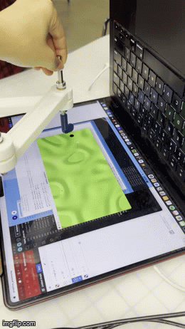
The mechanical foundation of our project is a two-degree-of-freedom planar pantograph, which we adapted from CAD files used by previous project teams. The original design was intended for a vertical orientation, but because our application required a horizontally mounted system to simulate a golf course surface, we made several key modifications. Most notably, we added a side support plate to stabilize the device in its new orientation and prevent unwanted vertical flexing during use. We also redesigned the base structure to accommodate potentiometer placement and cable routing.
To track the position of the pantograph’s stylus, we originally considered using encoders or magnetometers, but ultimately decided on analog rotary potentiometers mounted at the shoulder joints. Potentiometers offered several advantages for our use case: they are cost-effective, simple to integrate, and provide absolute position data without the need for zeroing or calibration on startup. While their limited resolution and restricted rotation range (typically ~270°) could pose constraints, these were well within the operating bounds of our pantograph’s motion.
Mechanically coupling the potentiometers to the rotating joints posed a design challenge. We evaluated several options including shaft couplers and belt drives, but settled on a gear coupling approach for its simplicity and precision. In our implementation, a small gear is mounted on the potentiometer shaft and meshes with a matching gear attached to the rotating arm of the pantograph. This setup ensures that the potentiometer rotates in sync with the joint, allowing for reliable and consistent angle measurement.
We 3D printed most of the pantograph components using PLA in the campus makerspace (Room 36), and iterated on the gear design to ensure a smooth and backlash-free engagement. The full mechanical assembly includes the base structure, linkages, gear-coupled potentiometers, and motor mounts. For initial testing and debugging, the electronics were assembled using jumper wires on a breadboard, with final soldering and cable management planned for the final integration phase.
Procedural Generation of Terrain Mesh
To create the 3D rendering of our golf course, we created a procedural generation technique in Blender with Geometry Nodes. We mapped a sample of ridged multifractal noise onto the height map of a 2-dimensional mesh grid. This was then processed through a biased interpolation function which just means that the noise was smoothed and that it bottomed out into flat sand pits. The terrain generation algorithm is designed with input parameters to adjust the density of ridges, the intensity of height mapping, and the size of the terrain frame.

This terrain mesh is exported as an object file which is a configurable filetype for mesh objects. To prepare this data for use in processing and on the Arduino, we had to create cleaning scripts. Specifically, to run our physics engine and drive our terrain-mapped force feedback bump illusion, we needed to be able to access the closest normal vector to a given point in the coordinate frame. We accomplished this with a python script. The object file first contains separately indexed and unordered lists of vertices and normal vectors. Then, it contains face information. Each face consists of three vertex indices and the associated normal vector index. The first step was to shred the object file and match normal vectors to vertices. Because it processes a triangulated mesh, each vertex is associated with 6 potentially-different normal vectors. These had to be matched and averaged. To access the appropriate normal vector in O(1) time, we decided to store the vertex-normal data as a flattened 2D array in a .csv file. In the X and Y plane, the object is a perfect grid, which means that each row and column have the same X or Y value. By sorted as X-row major, we could easily access the appropriate normal vector by indexing: ix * Y_LENGTH + iy.

To visualize our mesh in processing, we used a the 3D shape capabilities of processing and their simple light rendering system to show shadows. An orthonormal camera angle flattens the terrain on our display. This was tuned to emphasize the geography of our terrain map.

Global Positional Tracking
For tracking the horizontal x and vertical y position of the user with potentiometer values, we opted for a geometric approach. Reading the PTV09 potentiometer values for different absolute angles of the two links directly controlled by the motors shows that the values, although consistent, do not have a linear relationship. Through multiple angle measurements, we used the polynomial curve fit for each potentiometer value to find their respective link’s angle.


From the angles, we used trigonometric and triangular identities to identify the x and y location of the user.

Setting the lowest point as the origin, our pantograph has the following range of motion. These ranges are then used to scale with the virtual map’s coordinates and obtain the virtual position and required forces.

Force Feedback Control
Knowing the position coordinates in the virtual map, we accessed the corresponding force direction and magnitude from our normal vector .csv file. To get from the desired vertical and horizontal forces to the two motor torques, we used the following set of kinematic equations obtained from G. Campion, Qi Wang and V. Hayward’s paper [3].

Differentiating these kinematic equations to obtain the Jacobian returns the following partial derivatives.

The two motor torques were then calculated using the Jacobian and later the radius of the pulley and sector.

Physics Engine
We created a time-step iterative physics engine for our project. The position and velocity of the golf ball is updated at each loop based on the sum of the forces applied to it which include normal (from the terrain), friction (opposing velocity), and wall collision (stiff spring).

We directly translate collisions with the golf club into a change in velocity of the golf ball (based on impulse with 1.0 restitution, perfectly elastic). Then we translate that impulse to the user as a force over dt = 0.1s. We made it very high so it was distinguishable from the terrain bumps.
Results
At the project open house, we invited users to interact with the MicroGolf system and provide feedback on its responsiveness, realism, and engagement. The responses were overwhelmingly positive and confirmed that many of our core design goals, particularly around haptic perception and immersive feedback, were successfully realized.
Many users expressed surprise and delight at the tactile realism of the terrain, with comments such as “I can definitely feel the bumps and valleys,” “It feels like real terrain,” and “In all the contoured places it feels like the dominant direction of the gradient.” These responses indicate that our approach to terrain-based impedance variation and force rendering, driven by the local surface normals of the virtual mesh, was effective in communicating topographical features through the pantograph.
Users also noted that the system gave the illusion of three-dimensionality despite operating entirely in a flat plane: “Is it really 2D? It feels 3D!” This aligns with our findings from the literature on force dominance in haptic perception and confirms that our force feedback was strong and directional enough to override the flat geometry of the physical setup. Several users also commented on how sharp, directional forces during golf ball collisions enhanced realism, “Whenever I hit the ball I feel a sharp force in the other direction.”

Engagement was another consistent theme. Users described the interaction as “fun,” “smart,” and “cool,” with one saying, “Felt very engaged,” and another remarking, “Haha that is so fun! I can imagine you making this into a game.” These comments affirm that the experience was not only perceptually effective but also enjoyable, reinforcing the system’s potential as an interactive educational or recreational tool.
Some users asked questions about our technical implementation, such as “Did it require a lot of optimization with how you render the force feedback?” and “How did you get this rendered?” These questions point to curiosity about the underlying architecture and suggest that our system successfully conveyed a sense of engineering complexity and polish. One particularly insightful comment, “It’s so smart using the potentiometers so you don’t have to reset it each time,”affirmed our choice of sensing strategy and its impact on user experience.
Finally, we also received valuable feedback on system performance. One user noted that the ball occasionally "double collided like in pickleball," highlighting a potential improvement area in collision handling and force dampening. This kind of constructive comment will be helpful in refining our physics engine and feedback timing in future iterations.
In summary, the open house results validated many of our design goals: that the terrain should feel textured and 3D, that the system should feel immersive and physically responsive, and that the experience should be intuitive and fun. The user responses also helped identify concrete next steps for enhancing realism and stability, confirming that MicroGolf has strong potential as both a haptic demo platform and an interactive game.
Future Work
While the current implementation of MicroGolf demonstrates the core feasibility of our haptic mini-golf system, there are several avenues for future development that would significantly enhance its realism, functionality, and replayability.
One key area for improvement is the expansion of terrain-based feedback. Although our system currently differentiates between surface types like sand, fairway, and green through varied impedance values, future iterations could refine this further by adding texture-specific force profiles. For example, sand could include slight vibration to simulate granular drag, while rough terrain could resist directional motion more heavily than smooth greens. Incorporating an ERM (eccentric rotating mass) motor on the stylus handle could allow us to superimpose fine-scale tactile textures onto the existing kinesthetic feedback.
Another exciting possibility is introducing multiple golf clubs into the physics engine. Currently, the club’s effect on the ball is fixed, but in future versions, we could simulate different club types (e.g., putter, wedge, driver) by varying how much velocity is imparted to the ball from a given user force. This would allow the system to support more complex and strategy-driven gameplay, rather than serving purely as a single-interaction demo.
To move closer to a full mini-golf game experience, we also plan to implement a scoring system. This would involve tracking the number of hits required to get the ball within a defined target radius—our virtual “hole”—and displaying stroke counts and performance feedback to the user. Additional features like a visible flag marker, reset buttons, or a celebratory haptic cue on completion would help make the experience more engaging.
Because the terrain is procedurally generated in Blender and exported for use in Processing, our system already supports modular course creation. Future iterations could leverage this by allowing users to cycle through different course layouts at the press of a button or even generate randomized courses for each session. This would increase replayability and allow us to test how different terrain geometries affect haptic perception.
From a hardware standpoint, one unresolved challenge is the smoothness of the pantograph’s motion. While our current mechanical system is functional, some friction and backlash persist in the gear couplings and joints. Future versions could use ball bearings, higher-resolution sensors, or improved gear meshing to enhance mechanical responsiveness and minimize latency or instability during force rendering.
Finally, our system opens the door for future psychophysical testing. With further refinement, it could be used to study how visual and haptic cues are integrated during surface exploration tasks—particularly in flat physical environments like ours that rely entirely on force illusions to convey three-dimensional features.
In all, we view MicroGolf not just as a working prototype but as a platform for continued exploration into expressive haptic rendering, real-time control, and interactive virtual environments.
Files
The code used in this project are included in the file: Attach:MicroGolfCode.zip
The CAD assembly files are included in the file: Attach:MinigolfAssembly.zip
The Bill of Materials is included in the file: Attach:Bill_of_Materials-Sheet.pdf
Acknowledgments
We would like to thank the ME 327 2025's teaching team for their tremendous support throughout the project. We would also like to thank ME 327 2023’s "Haptic Air Hockey Simulation Device" group including Max Ahlquist, Dani Algazi, Luke Artzt, and Ryan Nguyen as well as ME 327 2024’s “Haptic Kong: Haptic Platform Game Using a Pantograph Controller” group including Courtney Anderson, Mason LLewellyn, Trevor Perey, and Kameron Robinson for their thorough documentation.
References
[1] Robles-De-La-Torre, G., & Hayward, V. (2001). Force Can Overcome Object Geometry in the Perception of Shape Through Active Touch. Nature, 412(6845), 445–448. https://doi.org/10.1038/35086588
[2] Ellis, R. E., Ismaeil, O. M., & Lipsett, M. G. (2009). Design and Evaluation of a High-Performance Haptic Interface. Robotica, 27(3), 321–330. https://doi.org/10.1017/S0263574708004707
[3] G. Campion, Qi Wang and V. Hayward, "The Pantograph Mk-II: a haptic instrument," 2005 IEEE/RSJ International Conference on Intelligent Robots and Systems, Edmonton, Alta., 2005, pp. 193-198, doi: 10.1109/IROS.2005.1545066, https://ieeexplore.ieee.org/document/1545066.
Appendix: Project Checkpoints
Checkpoint 1
Original concept imageL

So far, we have made significant progress on our project and have completed nearly all of the goals outlined for Checkpoint 1. Specifically, we have:
- Finalized our project scope and design,
- Assemble prototype frame using existing CAD files,
- Acquired the necessary components and materials,
- Selected the motors that will provide haptic feedback to the user, and
- Begun reviewing existing software tools that may assist us in implementing our own system.
We’ve also modified existing pantograph CAD files from a previous class project and begun prototyping the 3D printed parts with the necessary hardware such as bushings and shafts available in room 36. The original design was intended for a vertical orientation, whereas our project requires a horizontal setup. To accommodate this, we added a side plate to ensure stability when the pantograph lies flat.

One major design challenge was determining how to track the position of the pantograph’s stylus. Our initial plan was to use a magnetometer and a motor setup inspired by the Hapkit system. However, the CAD files we adopted used motors with encoders, which require more complex mathematics and calibration. Since we wanted to preserve the cleanliness of the existing CAD files and avoid extensive modifications, we pivoted to a different solution: attaching potentiometers at the joints of the pantograph.


This introduced its own mechanical challenges, particularly with how to connect the potentiometers securely. We initially considered shaft couplings but eventually opted for gear couplings. In our current prototype, a gear connected to a potentiometer is attached to the base and rotates as the base pantograph joint rotates for each of the two links. Since we only require the angles of the two base links to find the position of the end effector, we will only place two potentiometers at the base links. This approach is both simpler and more cost-effective than using motor encoders. Additionally, potentiometers track absolute position without the need to zero out each time, which is an advantage. While their resolution is lower and they only allow for 270° of rotation, this range is within our system’s operating bounds and should be sufficient for our application. The only concern moving forward is mechanical wear, which we will evaluate through testing and prototyping in the coming weeks.
Meanwhile, we've also started work toward our next checkpoint. Specifically, we’ve begun developing the virtual environment for our project by designing a custom micro golf course in Blender and importing the mesh into Processing. Our setup allows for randomized course generation so that a new course can be generated at the click of a button using filtering techniques. A high quality birds eye view will be rendered in blender and overlaid to the screen via Processing. The array of normal vectors from the mesh file will be used to create the bump valley illusion in 2D. Each point will also be coded with one of four textures: green, fairway, grass, and sand (in order of increasing friction). These will determine the linear damping of the club. We have also found resources about replicating the textures and might extend to include a small ERM motor on the handle.

Overall, we’re very encouraged by our progress and feel confident that we’re on track to meet our future milestones.
Checkpoint 2
We have made significant progress toward achieving our Checkpoint 2 goals, and our project is starting to come together both physically and virtually. One of our biggest accomplishments so far is completing the full mechanical assembly of the pantograph device. We've successfully integrated the electrical and mechanical components, allowing us to begin real-time interaction between the hardware and software systems. Although we are still using jumper wires during testing, all key subsystems—sensors, motors, and the mechanical linkages—are working harmoniously. Final soldering and cable management will follow once all calibrations are finalized.


On the software side, we’ve started developing the mathematical framework necessary to perform forward kinematics from analog potentiometer data. This allows us to track the position of the pantograph’s end effector in real-time. We’ve used the Serial Monitor to verify sensor readings and establish the min-max bounds for calibration, which will enable smoother and more accurate movement mapping in the future.
To drive the interaction between the physical pantograph and the virtual environment, we are employing a forward kinematics model derived from the geometric configuration of our mechanical linkage. As shown in the first diagram, we model the pantograph as a system of rigid links with fixed lengths (labeled as a1 through a5) and joint angles (measured as angle1 and angle5), which are read from potentiometers. Using trigonometric relationships, we compute the coordinates of key joints in the linkage such as point 2 and point 4, and derive intermediate positions such as the horizontal projection point and point 3 through a series of vector and scalar projections. This allows us to track the position of the end effector, point 3, in Cartesian space, which is essential for correlating user motion with virtual terrain location.
The second diagram expands on this by showing how the positions of various joints change in response to small changes in the joint angles. These derivatives are crucial for understanding the sensitivity of the system. Specifically, how small variations in angle affect the final position of the end effector. This analysis is particularly important for implementing haptic feedback: by computing these spatial gradients, we can determine how much force the motors should exert based on the properties of the virtual terrain. For instance, surface types like sand, fairway, and green each impose different levels of resistance to movement. We simulate these differences by varying the motor response according to the calculated gradient of displacement. Additional parameters like the horizontal offset, diagonal length, and vertical height between joints help us define the exact geometry and calculate physically accurate feedback forces.
By combining forward kinematics with gradient-based feedback control, our system produces spatially accurate and physically responsive motion. This allows users to feel realistic terrain features through the pantograph handle, making the virtual interaction immersive and intuitive. The mathematical modeling described here is foundational to our goal of delivering real-time, high-fidelity haptic feedback.
We’ve also fully completed the design of our virtual environment in Blender, including terrain features and texture mapping. The environment is now being meshed and exported for use in Processing, where it will provide the visual interface for user interaction. In parallel, we’ve begun integrating the motors and have started writing scripts to generate force feedback in response to user movement. This is a major milestone in our implementation of haptic feedback, as we are beginning to simulate physical resistance based on virtual terrain.
In terms of interactivity, we've started discussing and testing impedance variations for different surface textures within the virtual environment. For example, we are experimenting with different resistance profiles for sand, fairway, and green textures. These variations will be essential to delivering a realistic and immersive user experience.
Of course, this progress has not come without its challenges. A major obstacle was getting all the press-fit components to assemble correctly, requiring several design iterations. Additionally, the horizontal orientation of our pantograph introduced unforeseen load-bearing stresses. We addressed this issue by modifying the structure to include a support shaft running through the center, which significantly increased its mechanical stability. These physical adjustments were necessary to ensure consistent and repeatable motion during use.
Our current Checkpoint 2 goals include:
- Developing terrain-rendering software in Processing
- Writing Arduino code to implement basic haptic feedback
- Beginning hardware-software integration
- Implementing terrain-based impedance variations
- Testing basic end-to-end interaction: movement to feedback to visual update
We’ve made strong progress on all fronts. The terrain-rendering and integration tasks are well underway, and our initial feedback loop: user input, system response, and visual output is beginning to take shape. Some goals, particularly the implementation of nuanced impedance variations and refined force feedback, are still in early testing and will be further developed in the next phase. We have made significant progress towards our goals and we are right on track to complete our next checkpoint goals before demo day.
