

2026-Group 12

Caption:
A wearable haptic knee brace that provides active torque and vibrotactile feedback to guide safe rehabilitation exercises and reduce reinjury risk. SEE DEMO HERE: https://youtube.com/shorts/m4Dg3aYDops
Smart haptic Knee Brace
Project team member(s): Julien Buist-Thuillier, Nolan Jetter, Saran Grandhe, Cyrus Xiang, Adam Blanchard
When returning to playing a sport from an injury, athletes/patients can overexert themselves, causing reinjury. This can be caused by overuse, too high of force on the injured region, or going beyond the healthy range of motion post operation. The motivating idea is that there are 3 common ways to re-injure a reconstructed ligament: overuse, too high of a force, and extension beyond safe range of motion. After ACL surgery (and many other knee operations), a brace is commonly used to stabilize the joint. It is often difficult for the patient to discern when they are overusing, putting too much force, or straining the joint in unsafe ways. In addition, after talking to PT, people�s memory of technique and depth drifts over time, resulting in patients carrying out exercises in the wrong way. This is a serious problem for both patients and PTs. Therefore, the goal is to design a haptic feedback brace that helps the patient understand the safe limit of their body and to track recovery. Since the brace is intended to be used while squatting, hopping, or performing similarly high energy activities, understanding the range of possible dynamics and impedances of the knee will be critical for ensuring the passivity of our design and the safety of the athlete/patient.
On this page... (hide)
Introduction
This project studies the use of haptic feedback to create safer and more effective rehabilitation devices. Following ACL reconstruction, patients must carefully limit knee motion and loading during recovery. Conventional braces typically enforce these limits through rigid mechanical constraints that can make returning to exercise clunky and frustrating. The haptic knee brace design introduces a programmable virtual wall that provides controllable resistive torque as the user approaches unsafe joint angles, along with vibrotactile cues for real-time guidance. Through kinesthetic feedback with the virtual wall, the brace keeps users in safe ROM (range of motion), speed, and force. Simultaneously, custom vibrotactile feedback provides idealized feedback for proper form to help stimulate optimized recovery.
To narrow the scope of the project, the brace focused on rehabilitation and motion restriction during squatting exercises. The squat motion provides a common motion to study the two primary objectives of the brace. First, we aim to understand the impacts of different virtual wall transparencies for the effectiveness of safe rehabilitation and training. Second, we aim to investigate how squat form can drive communicative vibrotactile feedback and assess the efficacy of various haptic illusions on ERM arrays. Ultimately, the project serves as a platform for studying kinesthetic and vibrotactile haptic rendering, human perception of force feedback, stability-transparency tradeoffs, and closed-loop mechatronic control. Haptics is a natural solution for rehabilitation braces (exoskeletons) because it enables adaptable, software-defined motion constraints that can evolve with a patient's rehabilitation progress.
Background
The integration of haptic feedback into physical rehabilitation spans wearable tactile alerts and large-scale clinical exoskeletons. Designing a portable, closed-loop knee brace requires a synthesis of human-centric feedback design, robust wearable sensing, and compliant kinesthetic control.
Cognitive Mapping:
Wearable haptics must translate biomechanical errors into intuitive cues without causing cognitive overload. Lurie et al. (https://ieeexplore.ieee.org/document/5945455) established a four-stage framework for gait retraining: sensing movement, modeling kinematics, computing errors, and delivering feedback. When evaluating multi-parameter guidance for knee osteoarthritis, the authors discovered that simultaneous multi-joint feedback degrades user perception and overwhelms cognitive bandwidth. They concluded that staggered feedback schemes targeting one motion at a time are most effective, and that "pull" mapping analogies (moving toward the stimulus) yield faster human reaction times than "push" mappings.

Sensors:
To dictate when to deliver feedback, systems require precise, real-time kinematic data. Gong et al.(https://doi.org/10.1145/3737903.3768569) developed KneeSense, a smart-textile knee brace designed for in situ exercise form assessment. To overcome the inherent integration drift of standalone Inertial Measurement Units (IMUs), the authors integrated a thigh-and-shank IMU array with a medially mounted Time-of-Flight (ToF) range sensor. Bouncing infrared pulses off the contralateral knee establishes an absolute spatial anchor, enabling the system to extract four key performance metrics per repetition: knee flexion angle (depth), angular speed (tempo), knee-to-knee range (valgus collapse), and an acceleration-based instability index. While the authors noted that adding "adaptive haptic guidance" was a critical next step, their sensor-fusion pipeline provides a robust framework for real-time knee tracking.

Kinesthetic Impedance and dynamic virtual boundaries:
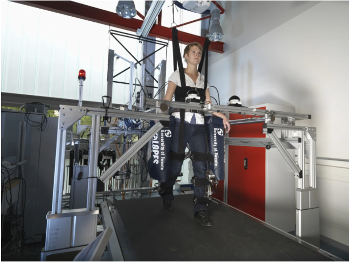
While tactile cues provide effective semantic alerts, they cannot physically restrict unsafe trajectories, which is crucial to avoid reinjury. Fleerkotte et al. (https://link.springer.com/article/10.1186/1743-0003-11-26) addressed this by evaluating compliant, variable-resistance boundaries using the LOPES gait trainer, a Bowden-cable-driven robotic exoskeleton. Unlike rigid, position-controlled rehabilitation robots that suppress active patient participation, LOPES utilizes an "assist-as-needed" impedance control strategy. The system models a normative reference trajectory surrounded by a programmable "virtual wall" or force field. It renders zero impedance during safe movements but smoothly ramps up resistive forces if the user deviates past a safe threshold, significantly improving walking metrics in spinal cord injury patients.
Our smart knee brace is first of its kind, portable kinesthetic+vibrotactile feedback-based knee brace with an app to get entire control of the healing process. We adopt the four-stage framework from Lurie et al., utilizing the "pull"-mapped feedback principles to minimize cognitive fatigue during squat rehabilitation. Gong et al. inspired us with the necessary kinematic metrics. Crucially, rather than relying on a massive clinical exoskeleton, we miniaturize the concept of a programmable "virtual wall" (similar to the ME327 Hapkit).
Methods
Hardware Design and Implementation
Mechanical Design
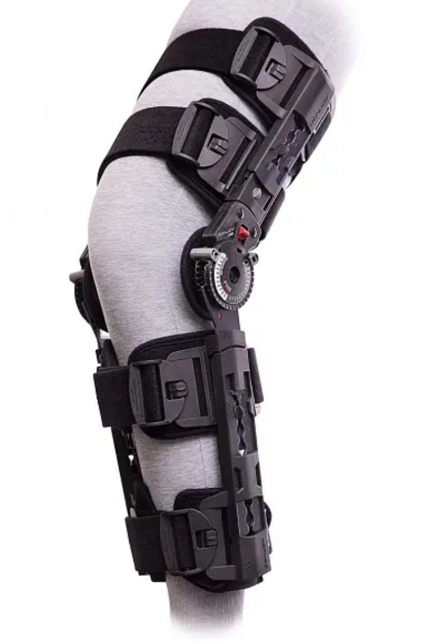
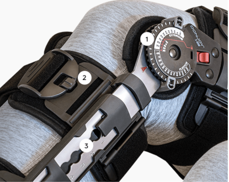
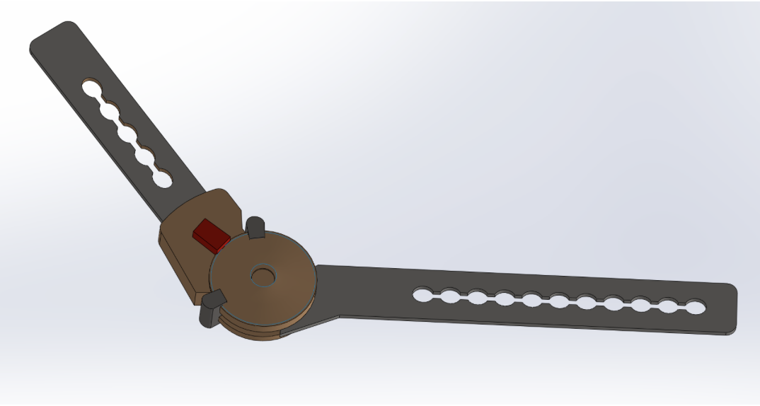
One of the largest challenges while designing exoskeletons and other wearables is securing the device to the body. To reduce the design scope, this smart haptic knee brace is built on top of an existing typical ACL recovery knee brace. The selected knee brace consists primarily of two rigid side members/rails connected by a mechanical hinge at the knee. The brace is designed to stabilize the knee and guide its motion primarily in flexion and extension while limiting unwanted rotational and lateral movements. Our design retrofits this existing hinge with a capstan-driven actuation system, effectively converting the passive brace joint into an actively actuated one to render the haptic effects.
The capstan transmission is designed to apply torque in only one direction, corresponding to knee extension assistance, or virtual wall feedback. The purpose of the device is not to increase training load for healthy users; instead, it�s designed to deliver haptic cues that encourage the user in a rehabilitation squatting exercise to stand up when a prescribed squatting position limit has been exceeded. Because torque is required only in a single direction, a bidirectional Hapkit-style capstan transmission is unnecessary. Avoiding a bidirectional design also eliminates the need for very high cable pretension (calculated to be around 150N), which would otherwise be required to prevent cable slack while transmitting the target joint torque.
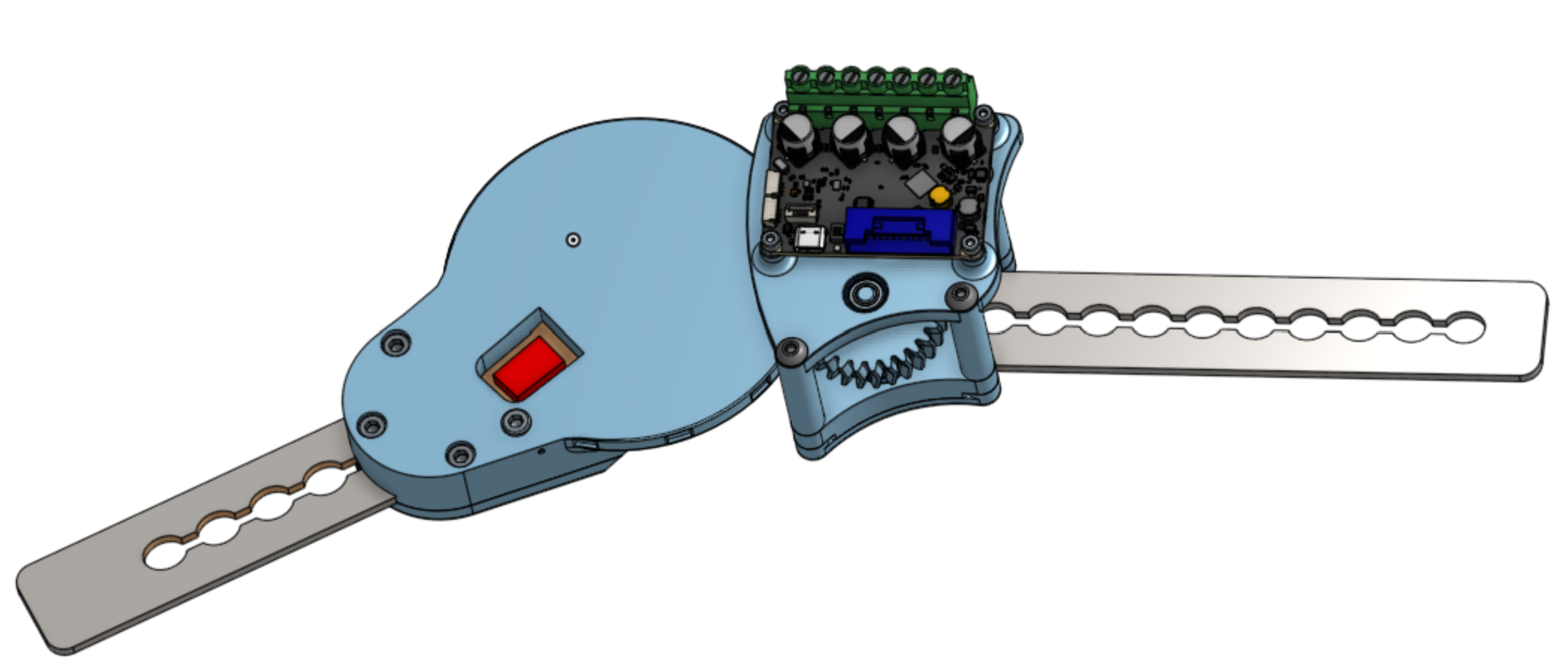
The motor and small drive pulley are mounted to the brace member attached to the lower leg, while the large driven pulley is mounted to the upper-leg member. The rotational axis of the large pulley is concentric with the existing brace hinge axis. As a result, torque generated by the capstan transmission is applied directly to the knee joint through the brace hinge without requiring additional linkage mechanisms.
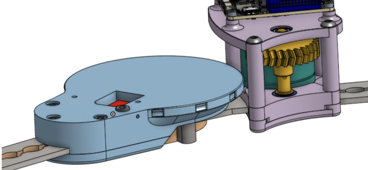
Before designing the actuation system, a CAD model of the knee brace was created through careful measurement of the commercial product. An accurate model was necessary to design mounting features that matched the brace geometry to render proper and secure attachment. The original brace hinge was permanently assembled using rivets. Rather than disassembling and modifying the factory joint, which would risk damaging the brace and increase complexity, the pulley was designed to be installed directly over the original joint through snap-fit and secured to the brace�s metal side rail through bolts.
Mounting stiffness was a key design consideration. Any compliance or looseness in the attachment interfaces would allow relative motion between the haptic mechanism and the brace, which in turn introduces backlash into the drivetrain and reduces haptic fidelity. Furthermore, if the large pulley does not fit tightly with the brace hinge, it becomes a long cantilever configuration since it�s bolted to the side rail at a distance. Under cable loading, it would experience a large stress concentration.
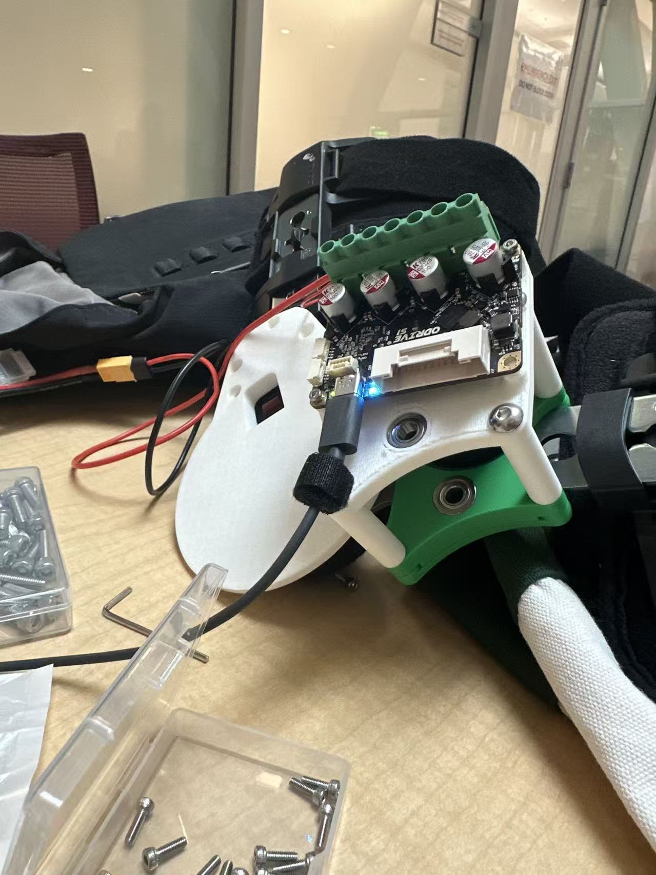
The purple motor mount serves as the support for the motor, the first-stage gear reduction, and the ODrive controller. The ODrive board contains an on-board magnetic encoder, and a diametrically magnetized encoder magnet is mounted concentrically on the rotating gear attached to the motor shaft. Accurate operation of the encoder requires the magnet and sensor to remain properly aligned and separated by the specified air gap. Integrating the motor and controller mounting features into a single rigid structure helps maintain this alignment while reducing part count and simplifying assembly. For compactness, the driven gear is integrated directly with the small capstan pulley. The resulting gear-pulley assembly rotates on a shaft supported by two bearings mounted in the top and bottom plates.
ERMs
To ensure high sensory transparency of the tactile feedback, various mechanical integration strategies were evaluated. The design process focused on balancing structural vibration transmission with ergonomic compliance, guided by sensory homunculus.
The mechanical integration of the ERM actuators onto the knee brace was driven by three primary design requirements:
- Maximizing Vibration Transparency: Ensuring the mechanical energy from the ERMs is efficiently coupled to the user's skin with minimal attenuation.
- Comfort and Ergonomic Conformity: Designing mounts that comply with the complex geometry of the user�s leg
- Vibration Isolation: Preventing false tactile triggers.
Initial Prototyping & Material Exploration
Initial prototyping explored modular, dedicated ERM mounts equipped with Velcro backing for adjustable positioning along the knee brace padding. Two materials were tested: Thermoplastic Polyurethane (TPU) and Polylactic Acid (PLA).
While the flexible TPU mounts provided excellent geometric conformity to the leg, the low material stiffness significantly damped the vibrations, leading to poor tactile transparency. Conversely, the rigid PLA mounts transmitted vibration energy with high efficiency but introduced usability issues due to their inability to conform to the limb profile.

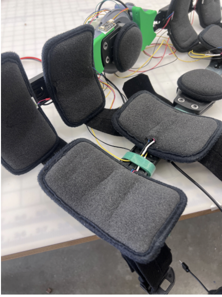
Sandwich Assembly
To overcome the trade-off between conformity and transparency, the strategy shifted to sandwiching the ERMs directly into the brace�s sponge padding. Slits were made into the padding fabric, allowing the ERMs to be housed internally.
To optimize vibration within this compliant housing, a rigid PLA structural holder was designed for each ERM. This approach allowed the rigid enclosure to maximize local vibration coupling to the skin and simplify wire strain relief during assembly, while the surrounding foam padding provided the necessary ergonomic conformity and isolated structural cross-talk.

To ensure the user could accurately localize which actuator was firing, the spatial distribution of the array was designed around the constraints of the human sensory homunculus. Because the lower limb exhibits a lower tactile spatial resolution (two-point discrimination threshold) compared to the upper body, the eight ERMs were separated by maximum permissible distances.
This physical isolation effectively mitigated sensory blurring, allowing the user to distinctively localize vibrotactile cues during squat.
Motor Sizing:
Given the strength of a human leg, sizing the actuator that renders the virtual wall is critical. An example motion capture data from Stanford�s ME 281 course shows that the human knee produces a maximum of 0.5 Nm/kg at the knee. Given an average human weight of 60kg, humans produce on the order of 30 Nm joint torque at the knee while walking.
Studies have found that the knee can produce moments up to 100-300Nm during intense barbell squats Escamilla. Market research into existing knee exoskeletons suggests that knee actuators are typically 50-70 Nm.
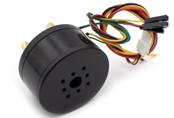
Initially, one of the concerns when designing the brace was sizing the actuator and gearing deftly to avoid injuring the user during testing. With these magnitudes in mind, the primary challenge was instead to select an actuator and ratio that was strong enough to even be felt by the user. A brushless gimbal motor with a stall torque of 0.3Nm ultimately was selected for this application due to its compact size and relatively high torque to keep the system size and weight reasonable. A total gear ratio of 21.6:1 was achieved with a single stage gear ratio and a large pulley reduction, resulting in an ideal output torque of 6.48Nm.
System Analysis and Control
In order to determine if the 6.48Nm was enough to be felt, several simulations were conducted. 6.48 is far smaller than the knee is capable of producing, and several times lower than some commercial exo�s, so the primary concern was actuator saturation. This would lead to a very weak virtual wall, defeating the purpose of the brace entirely.
In this simulation, the person in the squatting motion is modeled as a 1 DOF rotational system. The objective is to understand the magnitude of strength that the brace would have. Several critical assumptions were made for this analysis. First, the user is assumed to travel in a slow squat to 60 degrees from vertical in 3 seconds. The user is modeled as an inverted pendulum from the knee with a point mass as the torso. A torso mass of 40kg with a thigh length of 30cm were assumed for these calculations. Using the known time to rotate a distance, mass, and geometry, the squatting motion was modeled as a �damped free fall�. Numerical integration was used to calculate an equivalent damping coefficient that matched the desired time. In reality, the slowed motion during squatting is due to the resistive force of the muscles during the eccentric phase. The knee angle trajectory of the free fall was then compared with that when a virtual wall is present. The numerical integration is governed by the equation:
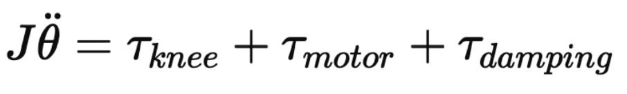
The knee torque is calculated based on the moment induced by the center of mass being some horizontal distance along the thigh away from the joint. The motor torque is calculated based on a virtual wall haptic rendering algorithm. The damping term is based on the damping term found previously. The moment of inertia of the system is modeled at the same point mass at a distance L (the thigh length of 30cm) from the knee joint. For the sake of this analysis, a virtual wall angle of 30 degrees was chosen. These assumptions resulted in the following position versus time plot:
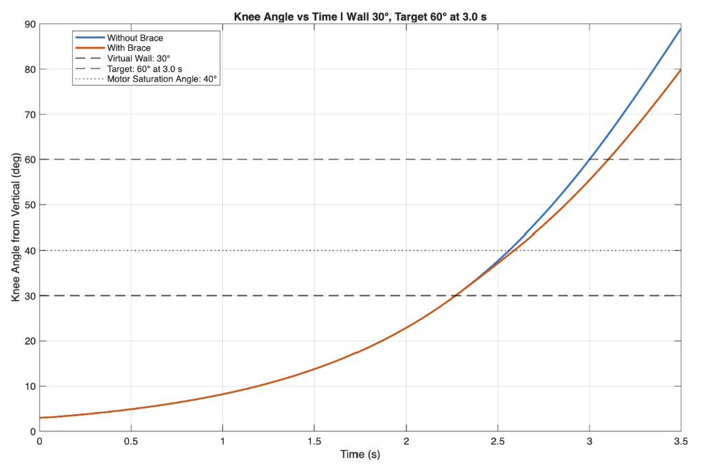
Though based on a very crude model with many assumptions, these simulations demonstrated the degree to which the system is underpowered compared to the knee joint and torso mass. The brace only reduced the time to travel 60 degrees by 3%. It should be noted that in reality, the user would not experience damped freefalling, and interpret the haptic signal to slow their squat. Another revealing plot from this dynamical simulation is the force vs time plot:
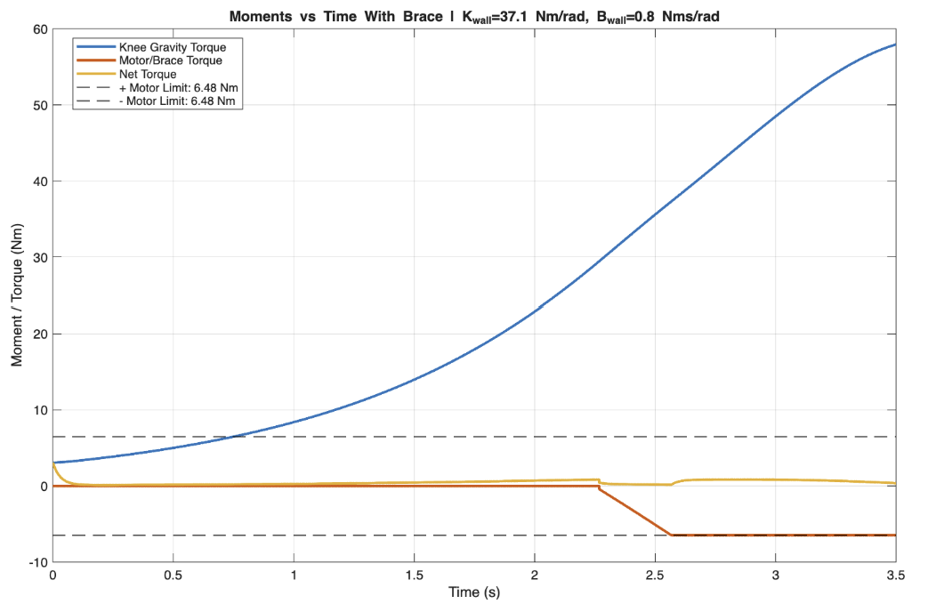
The difference between the knee moment in this simulation and the moment generated by the brace is clear. The moment produced at the knee is on the order of 5 to 10 times that of the motor, completely saturating the system during this simulation. Both of these plots reveal that to truly create a stiff virtual wall during squatting, a much stronger motor and/or gear ratio are required. Though these results indicate that the system will not be able to provide such limiting resistance on the leg, the feel may be profound enough to impact user behavior. This will be discussed in the results.
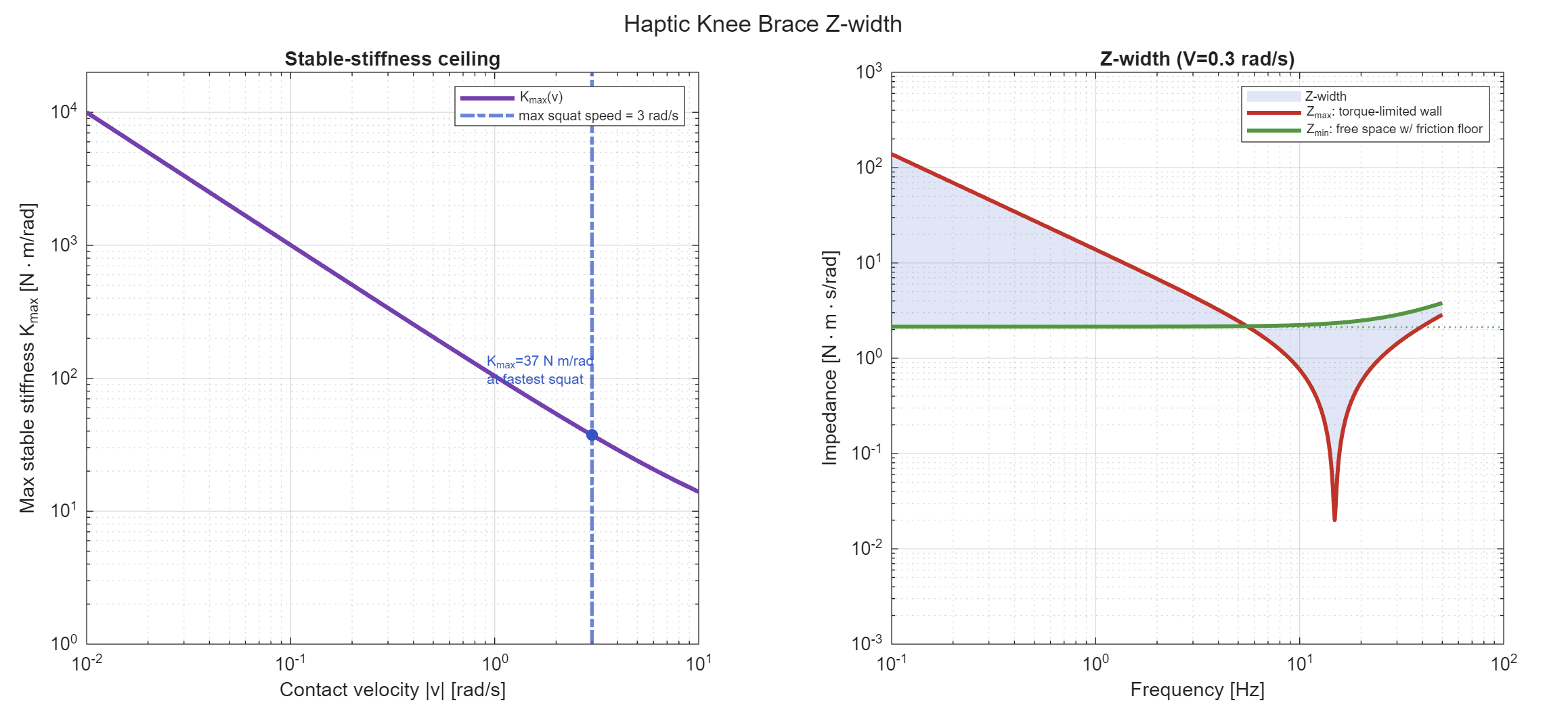
For stability analysis, the following quantities were reflected to the knee joint
Encoder Resolution = 4096 * 21.6 = 88,474 counts/rev
With such a fine resolution, we determined that the encoder quantization is not a limiting factor in the stability of the system. Estimating the rotor as half the mass of the motor acting at a radius of 20mm the motor reflected inertia is:
J = 21.62 * 0.06kg * (0.02m) = 0.012kg*m2
We consider both viscous damping and Coulomb friction, where the reflected viscous damping (b) from the motor bearings and eddy-current losses is estimated as being on the order of 21.62 * 50-5 = 0.02 Nm*s/rad while the reflected coulomb friction (fc) due to the brace joint, gear mesh friction, and the reflected rolling resistance of the bearings was estimated as being on the order of 0.5 Nm. The mechanical impedance of the device was calculated as follows:

An energy based stability model was used to compensate for the fact that the dominant energy dissipation is from coulomb friction:
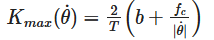
Where T = 0.01s is the sample period. Estimating a reasonable squat speed at 3 rad/s, we determined a stable Kmax<37Nm/rad:
Electrical
Kinesthetic Control:
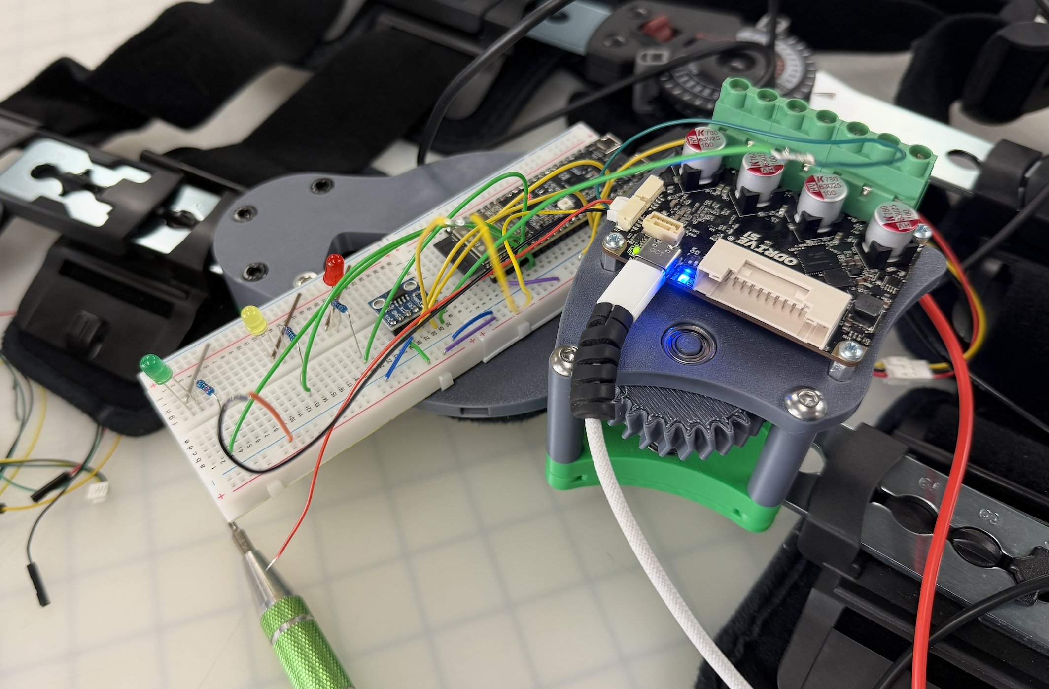
After choosing the brushless motor, the core electrical challenge was developing an architecture that allowed the motor to be commanded through custom haptic rendering algorithms. Driving a brushless motor required the use of an electronic speed controller (ESC). The ODrive S1 was selected as the ESC for this project given its prominence in high precision robotics and ease of customization through the ODrive tool.
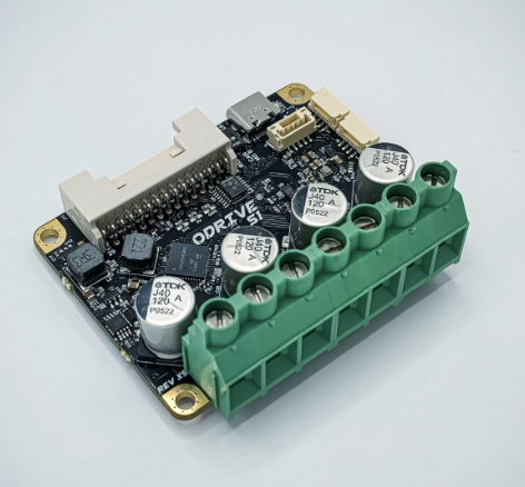
The ODrive was configured for sensored FOC mode with the 4015 BLDC. A magnet was mounted to the rotor of the BLDC, which was read by the internal encoder on the S1. This necessitated the ODrive to be mounted directly in alignment with the motor center. Encoder feedback is critical for smooth FOC motor operation, and for haptic rendering algorithms to track the joint angle of the knee.
The S1 serves as an intermediate layer between the motor and custom haptic rendering algorithms. All custom software is written in arduino C++ and runs on an ESP32 S3 N8R8 microcontroller. The Controller Area Network (CAN) communication protocol was used to communicate between the ESP32 and the ODrive. The ESP32 does not feature an internal CAN transceiver, so the sn65hvd230 CAN transceiver was used. ODrive features a CAN API to read available data and to control the motor according to the programmed control scheme. This scheme allows the ESP32 to read the encoder position from the ODrive, fuse other sensor data, and then command a motor torque back to the ODrive for the motor.
To power the motor, a common 6s 3,500mAh LiPo battery was selected. This pack was chosen due to its high current and capacity in a compact form factor. Additionally, the pack was easy to source within the team for this rudimentary prototype. Future work could benefit from alternative battery selection and orientation to best integrate into the rest of the system.

Vibrotactile Control:
Another goal of the project was to create an array of ERM motors that could be used to experiment with vibrotactile feedback patterns on the brace. Because the ESP32 can not supply the 85mA required for each of these ERM motors from the GPIO ports, external circuitry to power and control each from a microcontroller was required. The final design included 8 independently controlled ERM motors, each utilizing a low sided N channel MOSFET switch circuit with a flyback diode. All of the ERM motors were powered off of a single MP1584EN buck converter capable of up to 3A. This converter steps down the ~25.4V battery to 5V, supplying ample power for the ESP32 and all ERM motors.
Sensors:
Sensors provide the ESP32 microcontroller with necessary data so that the haptic software can render proper feedback. The aforementioned magnet on the motor rotor and encoder is a primary sensor used to determine the angle of the user's knee. In addition, an MPU 6050 accelerometer was implemented over I2C to estimate the orientation of the thigh. One of the primary limitations to the single direction capstan was the inability of the encoder to track position on the upstroke of a squat. To account for this, the orientation of the gravity vector from the accelerometer was compared to the estimated value of the encoder to rewind the mechanism when tension was lost. This redundancy in pose estimation helps ensure reliable and repeatable kinesthetic haptic feedback rendering at the bottom of the squat.
Combined PCB for Simplicity:
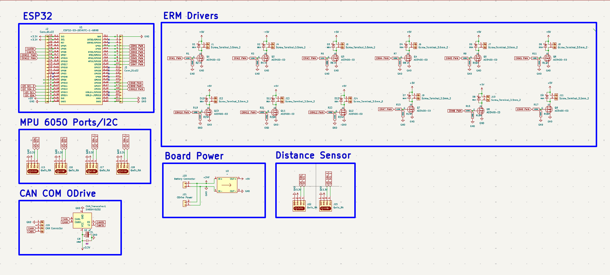
Given the complexity of 12 MOSFET circuits, buck converters, CAN transceivers, and sensors a custom PCB was designed for cleanliness. This board holds the ESP32 S3 N8R8 dev module, and easily connects each of the peripherals in a compact and reliable form factor. The PCB features the following:
- ESP32 S3 Dev Module
- MP1584EN Buck converter to 5V
- 12 ERM N MOSFET drive circuits
- MCU 230 CAN Transceiver
- Room for 4 MPU 6050 accelerometers
- Room for 2 VL53L1X distance sensors (future work)

Software
On a high level, the software for this project can be broken down into two main blocks: the iOS application for monitoring and controlling the brace, and the microcontroller state machine + mechatronics system that is responsible for reading data from the sensors on the brace and actuating the haptic controls on the brace. This second bit will require a deeper look so we can properly understand the implementation of the haptics rendering algorithms and the reasons for these choices. Additionally, the BLE communication between these two blocks constitutes its own segment that requires its own look to understand the system.
Let�s first take a look at the software app - in essence, the app can be broken down into two main pieces.
- Brace control panel that allows the user to connect to and set parameters for the parameter
- Session tracker that allows the user to monitor their active squat session to view things like angle, number of reps, and knee-to-knee distance.

The second major piece of software is on the mechatronics ESP side. This involves a more complex state machine that first waits to pair via bluetooth with the iOS application. After this has been completed, the system waits to receive the appropriate parameters from the brace control panel. The control panel indicates one of two potential modes: �virtual wall� mode and �assistance� mode. In the next bit, the user presses the �calibrate� button from the control panel. When this happens, the accelerometer y index is read as is the absolute encoder count. The encoder count then becomes the relative baseline that we use to map from encoder count into brace degrees. We use this mapping to then define where the virtual wall kicks in depending on the user-prescribed angle. Let's next discuss the two feedback modes.
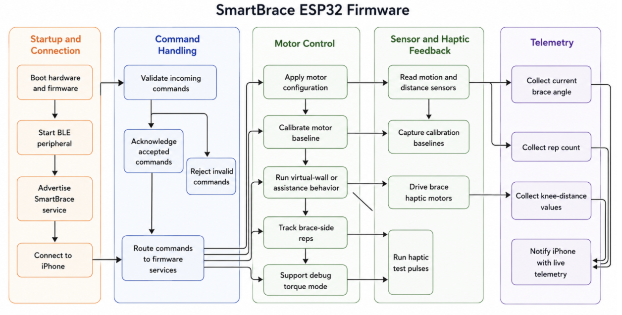
In the �virtual wall� mode we implement a linear kinesthetic and vibrotactile virtual wall at the desired angle. After testing with a couple of different mechanisms for producing the appropriate sensation, we found that linear was most appropriate as it allowed the user to push slightly into the �danger region� and understand how far past this wall they actually were. Alternatively, exponential decay feedback provided a stronger sensation of a virtual wall, but didn�t provide a mechanism for the user to appropriately understand depth. In addition to this wall, we also implemented a vibrotactile pattern during the first phase of the squat: as the user sits into the squat, the vibrotactile sensors (4 pairs along the length of the leg), would turn on and off as the user progressed through the squat to represent where they were. We found that this allowed the user to more appropriately identify how deep into the squat they were so they could modulate their biomechanics and dynamics more appropriately. An issue we often found without this feature is that the virtual wall felt �sudden� and the user had to respond quickly, anecdotally applying larger loads through their knee joint. A big challenge with this mode was that the motor only actuates in one direction so when the user is not actively in the virtual wall there is no encoder feedback to queue position. To get around this, we used the live accelerometer reading relative to the calibration position. When the y-reading of the accelerometer came to be within some small fixed threshold of the calibration position, we treated this as �end of movement� and commanded the motor to return to calibration encoder count before the next squat began. We also used this algorithm to increment the total number of reps. The other mode, �feedback� mode, was quite a bit more simple. It included all of the same vibrotactile haptic feedback components, but simply turned on the motor to the desired torque strength when the desired depth was met. Then, the motor was not turned off until we arrived at an encoder count that was close enough to the calibration mark.
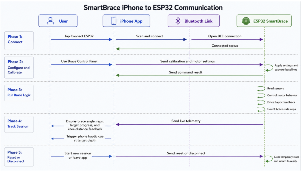
Finally, the communication between these devices. On the firmware side, we constantly drained any readings from the OCAN as fast as they came in and read out the other sensors at 100 Hz. This data was used to render haptic effects. In addition, the information was communicated to the iphone app with live telemetry at 10 Hz. Now, information traveling in the other direction (iOS -> firmware) was only carried out in the setup phase. Here, user interactions with the buttons are immediately communicated to the ESP32 over the BLE protocol.
Results
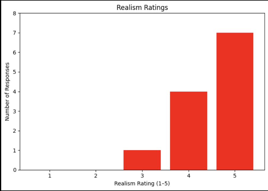
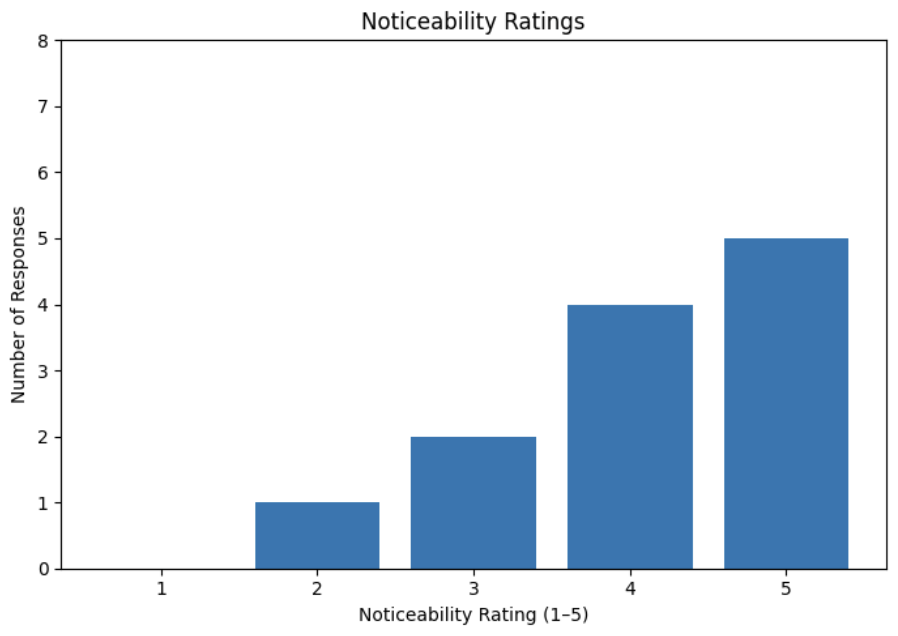
Above are the responses for both the noticeability and realism of the system as rated by people who interacted with the system on demo day. Although the majority of responses were quite positive (especially for realism), there were a couple of things that we would like to improve upon especially after seeing these results. First of all, we found that the system was a bit hard to understand. The combination of the different vibrotactile queues made it difficult to understand what was what and pinpoint exactly when the virtual wall kicked in. This, we believe, decreased our noticeability ratings. In addition to this, we found that people downrated the realism for two main reasons:
- The brace did not fit perfectly and inhibited the kinesthetic feedback
- The vibration sensation on the upper leg was hard to localize and felt quite weak.
Aside from these weaknesses, users found the device compelling in indicating depth and queuing the squat movement. Users also frequently commented on how they found the app to be a compelling tool to quickly adjust settings for the brace.
Future Work
Although the system is robust and produces quite good haptic effects, there are a couple of experiments that can be carried out to validate the system and improve the feedback that it provides to the user. First of all, before use in a clinical setting, we need to properly validate the knee joint angles that it enforces. While we mapped the motor encoder counts to the angle of the brace, we have not properly mapped how the angle of the brace actually maps onto the angle of the knee. In a setting where a patient is recovering from some injury, it is critical that the feedback provided accurately represents the ROM the patient SHOULD be moving through. Especially after testing, it is not so clear that the brace angle linearly maps to the knee angle. To test and validate, we would need to have users squat with the brace on while being captured by a marker mocap system. By setting up data collection properly, we can then understand the relationship between the brace angle and knee angle and feed this into our control system for proper control.
The next major thing that needs to be tested is the quality of both the kinesthetic and tactile feedback from the brace. The goal of the brace, after all, is to queue the user in depth so they progress through ROM properly in the recovery process. By testing different patterns (our currently implemented �progress bar� vibrotactile feedback + virtual wall, vibrotactile virtual wall, single/multiple discrete buzzes at depth) and different locations for applying the vibrotactile feedback on, we can understand what actually translates to a clear queue for the user.
There are four major areas for improvement of the system. The first of these is in the fit and ease of use of the brace. Currently, the device is built off of a standard knee brace for post-surgery stabilization. It unevenly actuates the leg - acting only on the later side of the knee - and fits loosely. Both of these combine to create a less than ideal kinesthetic experience. Building a full brace with even actuation would solve these issues. The second major improvement to make is on the controls side of the equation. Because the brace applies torque in only one direction, we need a better mechanism to �rewind� the motor. Additionally, depending on the results relating knee angle to brace angle, we will need more advanced controls. The third major improvement is in accessory features that help improve user feedback in the recovery process. Measuring valgus collapse with a time of flight sensor and measuring the speed at which the user performs the squat are two immediately obvious improvements that help define the quality of the movement. The final area for improvement is in the app - we need to build in longitudinal progress tracking and the storing of workouts so that patients and physicians can work together to understand progress, setbacks, and build trackable plans that get the patient back to 100% .
We see a very direct application for the brace in knee surgery recovery protocols - particularly in recovering from ACL injuries. When a patient, particularly an athlete, recovers from an ACL, a large portion of treatment involves recruiting the quad muscles to fire to appropriately stabilize the knee. This involves progressively deepening the squat over a period of months to build strength through larger and larger ranges of motion. These squats then become jumps which eventually turn into more dynamic, lateral movements. In existing protocols, physicians try to guide patients through proper range without the necessary quantitative tools to assess whether the patient is actually meeting these criteria and getting enough volume. The brace provides a means of tracking both of these, as well as assisting the user in leg extension where bodyweight proves to be too much load.
Files
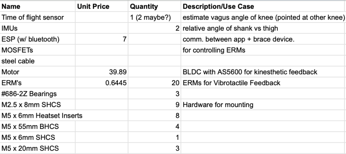
The final BOM can be found here: https://docs.google.com/spreadsheets/d/1ZQ_T1fqlkK6N0f4PSom9osINvLGCdKvs4Y1zhpbpSr0/edit?usp=sharing
OnShape CAD Project: https://cad.onshape.com/documents/2a76352bb397d1b4be2955aa/w/6053c45d5e9cd0d3c230d1cd/e/347b1cf7b5c89a2ae2f1a982?renderMode=0&uiState=6a21eb5097844f92df3ceaa3
Please email julienbt@stanford.edu for KiCAD Files
References
https://ieeexplore.ieee.org/document/5945455
https://doi.org/10.1145/3737903.3768569
https://link.springer.com/article/10.1186/1743-0003-11-26
Appendix: Project Checkpoints
Checkpoint 1
These are the planned tasks for checkpoint 1:
- Finalized BOM
- Initial CAD for motor mount and capstan
- Initial prototype of motor mounted to the brace
- KiCAD Schematic
We are currently on track with our Checkpoint 1 deliverables. Securing all necessary components is a major milestone, especially given the anticipated lead times. The overall product architecture- encompassing the mechanical design, electrical layout, and feature roadmap, is well-defined. In our current timeframe, we are confident in successfully implementing both the kinesthetic and vibrotactile feedback for knee flexion and extension. Functionally, the team is prioritizing squat tracking to provide real-time biomechanical feedback.
Finalized BOM:
Along with sourcing the knee brace, we also finalized the BoM and acquired all the components for MVP. Other components are decided and order's yet to be placed. For motor selection we benchmarked the torque an average human knee exerts and finalized the motor along with gear train design. Knee safety and the right amount of torque for a good kinesthetic feedback are considered.
Initial CAD for motor mount and capstan:
With the motor selected, we got the entire initial CAD made: the gear transmission, motor mount, and capstan drive. The mechanical advantage is gained through the gear reduction ratio and the pulley diameter difference in the capstan drive.
Initial prototype of motor mount:
KiCAD Schematic:
This is the completed circuit for the MVP product.
Checkpoint 2
These were the tasks completed prior to checkpoint 2 in accordance with the project proposal:
- Virtual wall implemented
- Retrofit encoder to the brace
- Tested haptic effects of ERM arrays
- All components have arrived and are being used in active prototypes
To achieve this, the following subtasks were completed:
- Full 3d printed prototype of drivetrain mounted to the brace
- Motor controller used to drive motor and resist squatting motion
- ERM array breadboard prototype testbed created
- ESP32 connected to motor controller over CAN protocol
In addition, the following tasks were completed:
- Custom PCB ordered and arriving Monday 5/25/26
- App created and connected to the brace for real time customization and calibration
For Checkpoint 2, we are currently on track with our deliverables. The most major milestone was the complete first iteration of the kinesthetic haptic feedback of the device. This can be split into three parts: physical validation of the mechanical torque transmission from the motor to the brace, validation of the electrical hardware and communication between various components, and haptic rendering algorithms.
First the mechanical system was validated through iterative 3d printed designs of the capstan drive and motor mount. After this was successfully implemented and the knee joint could be articulated by hand when rotating the motor, the motor controller was added. One major concern was the strength of kinesthetic feedback that the motor could apply during the squatting motion. To validate gearing and other mechanical properties, the controller was manually turned on during squats. These tests were paramount in ensuring proper gearing and strength for the selected motor. They also revealed some flaws in the drivetrain that were used to improve the design. The manual testing of the brace can be found here: https://youtu.be/0Y8oBaPidgA
After validating that the system could electrically power the brace using the motor controller GUI, an ESP32 microcontroller was connected to allow for custom code and haptic rendering algorithms. The team successfully implemented the CAN protocol between the ESP32 and motor controller to allow reading of knee encoder positions. This data was then used to generate torque commands to the motor controller that resist motion. This resulted in the first rudimentary virtual wall algorithm on the brace. This demo can be found here: https://youtube.com/shorts/Qk6qvu5L3qw?feature=share
The next major part of the project is to complete the vibrotactile feedback portion. This includes mounting the 12 ERM motors to the brace. This has not yet been fully implemented, but several tests were performed to design the idealized placement, array spacing, and actuation timing.
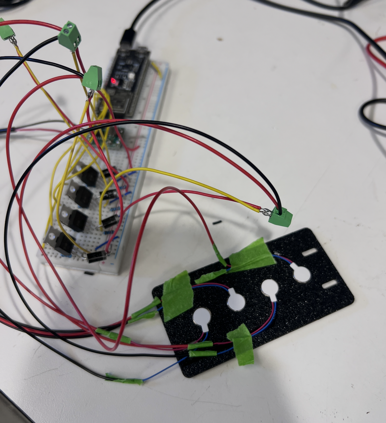
Another major milestone that we did not initially plan for was the design of a custom PCB for all of our ERM motors. After breadboard prototyping a few ERM circuits, the benefits of a compact SMD board for reliability of 12 ERM's became clear. This board was designed and has already been fabricated.

Given the current state of the project, the team is confident in the ability to complete the device for the demo. Several critical lessons were learned throughout this checkpoint, leading to improved designs moving into the final week. The remaining tasks include:
- Full testing of kinesthetic rendering on brace on user
- Add ERM motors to brace
- Add accelerometers and TOF sensor to implement advanced features
- Add PCB