2026-Group 14
The Vibro-TACTical Belt
Vibrotactile Haptic Belt for Covert Communication of UAS Threat Direction
Project team members: Joseph Heimerl, Andrew Pasco, Ashlynn Sweet, Brody Todd
This project investigates the use of torso-based vibrotactile feedback as an eyes-free, low-cognitive-load interface for conveying unmanned aerial vehicle (UAS) threat bearing to dismounted operators in high-stress environments. Motivated by the rapid proliferation of low-cost, highly effective UAV threats and the resulting need for covert, intuitive alerting mechanisms that do not overload visual or auditory channels, the project aims to bridge the gap between UAS detection systems and operator awareness. Building on established findings in haptic perception and prior systems such as vibrotactile navigation belts and tactical situational awareness displays, the goal of this project was to create a design that leverages the torso�s large spatial surface and the human ability to interpret localized vibration as directional information. System implementation consisted of an eight-actuator eccentric rotating mass (ERM) belt arranged at even intervals, an inertial measurement unit (IMU) for heading reference, and a Bluetooth-enabled motor driver that receives real-time threat bearing data from a simulated upstream detection pipeline. Detected threat azimuths are mapped directly to the nearest torso segment, producing immediate, body-referenced directional cues intended to enable rapid operator response. This project was demonstrated with great success at Haptics Open House with high rankings for noticeability and usefulness of the conveyed feedback information. In addition to user testing, a system analysis of the haptic belt is detailed below. Future work for this project includes additional experimentation to tune vibration signals for new threats near the wearer and full integration with a threat detection system.
On this page... (hide)
Introduction
Unmanned aerial vehicles (UAVs) represent one of the fastest-growing threats on the modern battlefield [1]. Commercially available drones, costing as little as a few hundred dollars, have demonstrated lethal effectiveness against dismounted infantry and special operations forces in recent conflicts. Counter-UAS detection systems using RF, acoustic, and optical sensors are currently being developed to give early warning time to the dismounted operator before the UAS threat reaches terminal range. Between each detection method, there remains the challenge of covertly notifying the operator without adding significant cognitive demands on the operator or requiring eyes-off-task. For dismounted soldiers operating in high-stress, visually saturated environments, there is a critical gap between threat detection and meaningful operator awareness. This project addresses that gap by exploring whether haptic feedback can deliver early UAS threat cueing in a form that is fast, intuitive, and eyes-free.
The educational motivation for this project centers on two core objectives of ME327: understanding how the human haptic perceptual system encodes spatial and directional information, and designing an actuator system that exploits these encoding principles effectively. Vibrotactile stimulation of the torso is well established in the literature as a viable channel for conveying directional information to a user without engaging visual or auditory attention. By distributing eight eccentric rotating mass (ERM) motors around a rigger belt at cardinal and intercardinal positions, we create a spatial display that maps detected threat bearing directly onto the body. This leverages the skin's sensitivity to localized vibration and the brain's innate ability to interpret torso-relative spatial cues.
The torso provides a large, stable surface area for spatial encoding, remains accessible regardless of what the operator's hands are doing, and does not compete with visual or auditory channels that are already saturated in a threat scenario. The device integrates an inertial measurement unit (IMU) for heading reference and a Bluetooth-enabled motor driver board to receive bearing data from an upstream detection pipeline, translating passive UAS localization into an immediate, actionable body-referenced cue. The goal is to deliver that cue within seconds of detection, providing enough warning for a soldier to take cover, cue a teammate, or engage a countermeasure before the threat is overhead.
Background
The idea of using the body as a spatial display is not new, but it remains an underexplored modality in real-world defense applications. The insight driving this entire field comes from the fact that the torso has a large, accessible surface area, and the brain already interprets touch on the body in a spatially referenced way. This property makes vibrotactile torso displays a natural candidate for conveying directional information in any context where visual and auditory channels are occupied or compromised.
The earliest systematic work on vibrotactile waist displays for navigation came from van Erp and colleagues, whose 2005 study in "ACM Transactions on Applied Perception" demonstrated that eight pager-motor tactors arranged around a waist belt could guide pedestrians through a waypoint course with high accuracy [2]. Critically, their design adjusted tactor positions to cover cardinal and oblique directions, and demonstrated the approach in higher-stress operational environments including helicopter piloting and boat navigation. The robustness of the tactile channel under physical stress, where vibration noise from the vehicle platform might be expected to drown out the cues, was one of the most operationally relevant findings of that work, and informs our confidence that a belt-based system could be effective in a dismounted warfighter context.
On the commercial and defense side, two systems stand out as the most mature implementations of this concept. The first is Elitac Wearables' Mission Navigation Belt (MNB), developed in collaboration with the Royal Netherlands Army [3]. The MNB uses seven evenly spaced vibration motors connected to GPS-based soldier systems to communicate waypoint directions, with the goal of freeing soldiers' hands, eyes, and ears for other tasks. The second relevant system is Engineering Acoustics Inc.'s Enhanced Tactile Situational Awareness System (eTSAS), which takes a different approach by targeting aviators rather than dismounted soldiers [4]. The eTSAS encodes spatial orientation information, including direction and magnitude of helicopter drift and altitude warnings, into vibrotactile patterns delivered through a belt worn under a flight suit. Army and Navy flight tests demonstrated that TSAS improved pilot performance in degraded visual environments and reduced workload in task-saturated conditions.
While each of these systems are useful test cases for torso tactile cueing, the haptic belt created for this project specifically addresses the problem of UAS threat bearing communication to a dismounted soldier. Rather than constant cueing for navigation purposes, our system must manage multiple threat detection and effectively warn the operator in a simplistic way that reduces additional cognitive load. Recent perceptual work has sharpened the design constraints for exactly this application. Research on azimuthal vibrotactile identification on the torso has shown that users can localize single-motor stimuli with very high accuracy, but that illusory stimuli used to increase angular resolution degrade performance substantially, suggesting that hardware motor count, rather than software interpolation, is the right lever for increasing directional resolution [5]. Separately, Stovicek et al. (2025) confirmed that walking does not significantly diminish a user's ability to localize haptic cues on the waist, with zonal accuracy remaining above 90% between standing and walking conditions [6]. Together, these findings point toward a design that uses a fixed number of physical motors at evenly spaced positions, prioritizes rear-torso coverage where perceptual accuracy is highest, and encodes threat bearing through motor selection.
Methods
To investigate whether vibrotactile feedback can serve as an effective interface for communicating UAS threat direction, we designed and implemented a complete wearable haptic belt system capable of receiving threat information, tracking user orientation, and rendering directional cues on the torso. The system combines custom mechanical hardware, embedded electronics, wireless communication, and real-time control software to translate threat azimuths from a global reference frame into body-referenced haptic feedback. The following sections describe the hardware architecture, software framework, and analysis methods used to develop and evaluate the prototype.
Hardware Design and Implementation
The hardware was designed around three primary requirements: (1) delivering clear and localized vibrotactile cues around the user's waist, (2) maintaining a covert profile and adjustable form factor suitable for wear by different sized users, and (3) supporting real-time orientation tracking and wireless communication with an external threat-detection source. To satisfy these requirements, the system consists of an eight-actuator vibrotactile belt, a central embedded controller with an inertial measurement unit (IMU), distributed motor-driver electronics, and a modular set of custom 3D-printed housings that integrate the components into a wearable platform.
Mechanical Design and Aesthetics
The main considerations in the mechanical design were to house and protect the electronics components, allow for adjustable configuring of the belt, and maintaining a sleek, "covert" overall aesthetic.
The belt system consisted of seven custom 3D-printed modules mounted on an off-the-shelf adjustable belt. The belt's Velcro closure allowed the overall circumference to be adjusted to fit a wide range of individuals, while the modular design allowed the spacing of the vibration motors to be reconfigured for different waist sizes while maintaining approximately 45� angular separation between each module. All modules were printed in black PLA on a Bambu X1E printer (courtesy of the PRL), chosen to give the system a low-profile, covert appearance consistent with a tactical wearable.
Module Types
Three distinct module types were designed, each measuring approximately 1.5 � 2 inches:
- Blank Module (�2): The simplest module type, housing only a single ERM motor. Used to fill the remaining angular positions where no additional electronics were needed.
- Driver Module (�4): Housed one DRV8833 motor driver breakout board and one ERM. A cover protected the electronics while keeping the wiring connectors accessible, secured to the module base using self-tapping screws.
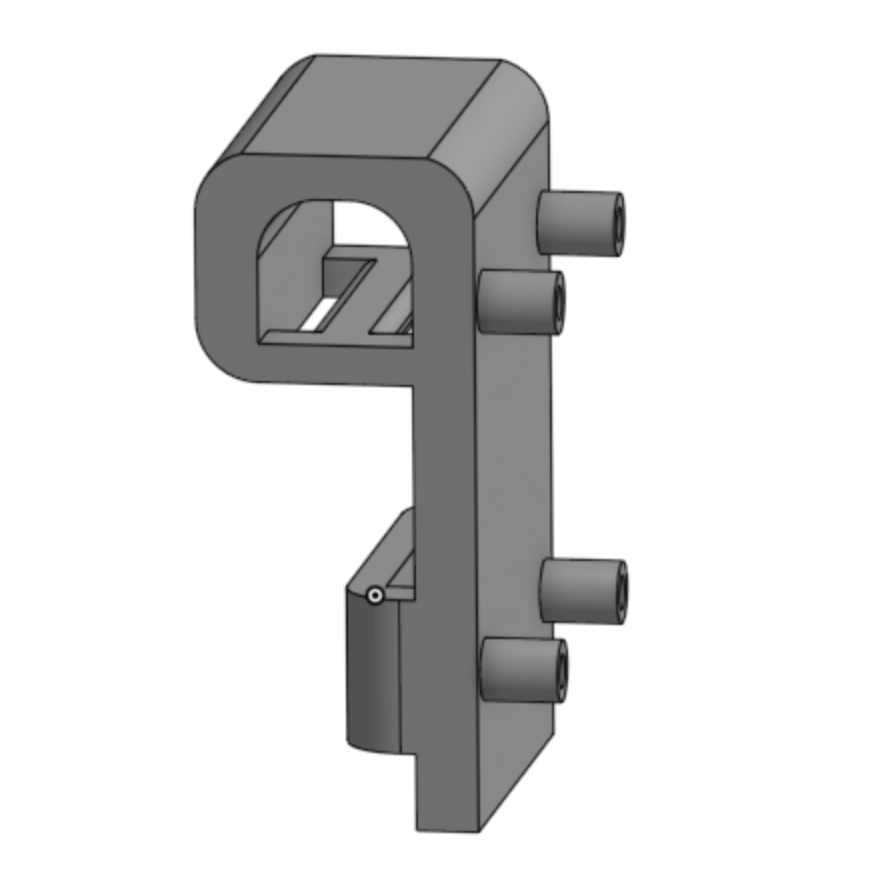
- Argon Module (�1): The central hub of the system, housing the Particle Argon microcontroller, the BNO085 IMU, the BLE antenna, and one ERM. Like the driver module, it featured a cover secured with self-tapping screws to protect the electronics while leaving connectors exposed for programming and power.

This module housed the Argon
microcontroller, the IMU,
the antenna, and an ERM.
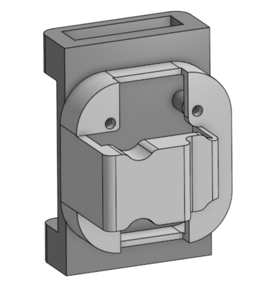
This module housed one motor
driver board and an ERM.
This module only housed one ERM.
The STL files are attached in our "Files" section.
Mounting and Adjustability
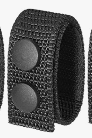
Each module was designed to attach to the belt via a belt-keeper loop on the rear, while also snapping snugly onto the belt to prevent unwanted rotation or sliding during use. Despite this secure fit, modules could still be slid along the belt to re-position them, allowing the system to be quickly reconfigured between users in under a minute. The front buckle of the belt was left unmodified; its flat interior surface served as a natural mounting point for the front-facing ERM, keeping the forward motor position consistent and centered regardless of how the other modules were adjusted.
Each module featured a flat interior face, contacting the wearer's body, on which the ERM was mounted. When the belt was worn snugly, this ensured firm, consistent contact between each ERM and the user's waist, which proved critical for effective vibrotactile perception.
Wire Management
Wiring between modules was routed internally through the module bodies where possible to keep the exterior clean and low-profile. Between modules, wires were protected with black braided sleeving, which matched the black PLA modules and belt hardware to maintain the covert aesthetic while also providing mechanical protection against abrasion and repeated flexing during wear. Additionally, a 3.7V 2000mAh LIPO battery was attached to the belt using velcro to provide the external power since the device was meant to be fully stand-alone and wireless.
Electrical Design and Schematics
We selected a Particle Argon microcontroller as the central controller because it provides both BLE connectivity and sufficient PWM outputs to drive the haptic actuators.
To control the vibration motors, we used four DRV8833 motor driver boards from Adafruit. Each DRV8833 can drive two ERM (eccentric rotating mass) motors using an H-bridge configuration. Although each motor can be controlled bidirectionally using two PWM inputs, our application only required unidirectional operation, so we used a single PWM-controlled half-bridge per motor.
For orientation tracking, we integrated a BNO085 IMU, which performs onboard sensor fusion and magnetometer calibration. The sensor communicated with the Particle Argon over an I2C interface, simplifying orientation estimation while reducing computational load on the microcontroller.
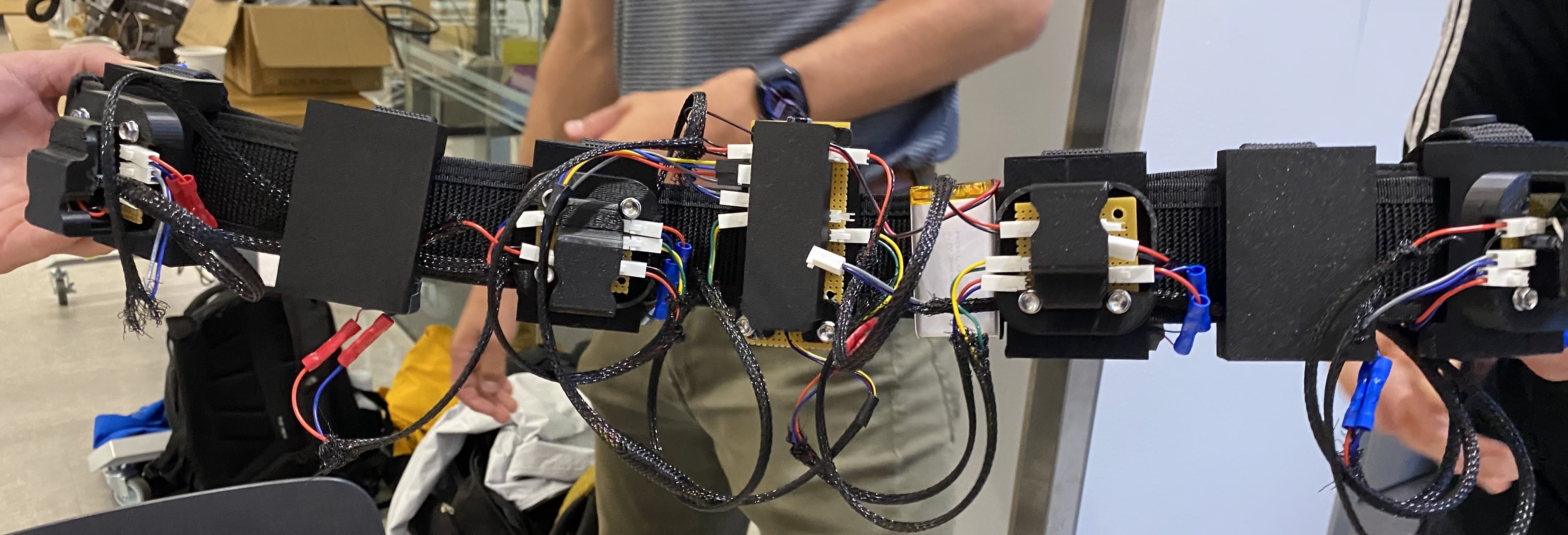
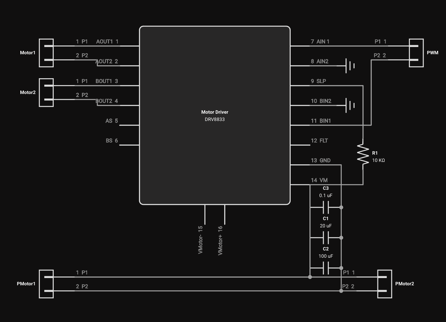
To simplify wiring, we positioned our motor drivers evenly around the belt, and soldered compact protoboards with molex connections for robust cable management. Because of the distances between our motor drivers and the power supply, we included a collection of capacitors next to each driver to mitigate the effect of the inductance in the long wires. The reason we have different valued capacitors in parallel is due to the nonidealities of real capacitors, which will have equivalent series inductance and resistance (ESL and ESR). This prevents larger capacitors from attenuating higher frequencies, and actually begin behaving like an inductor, amplifying voltage noise. The collection of capacitors chosen would provide current for the large current draw needed on motor startup (which is turns out to especially large for tiny motors as they have such little inductance), as well as the high frequency switching currents associated with draining the FETs. This was mainly necessary to reduce power supply noise as we were powering our motors and controllers with the same battery.

Fully assembled wiring harness

Back of two motor driver protoboards
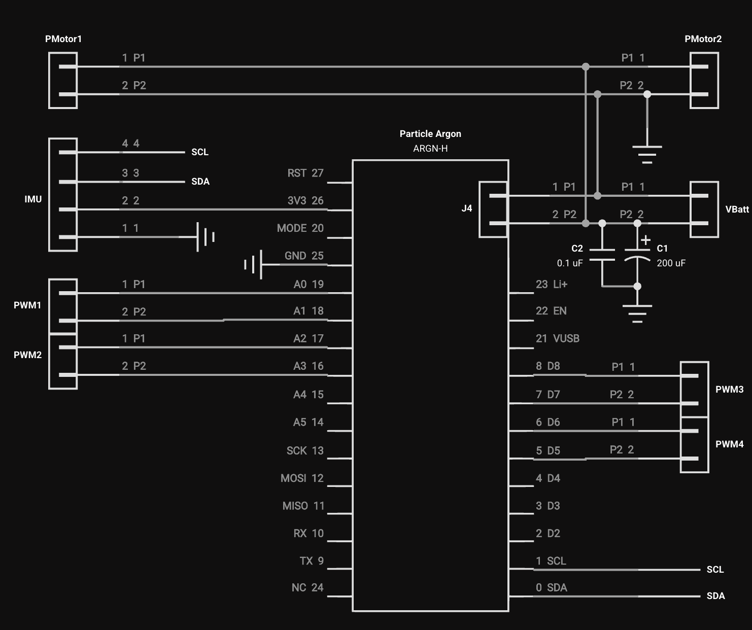
Below are the finalized functional schematics for our protoboards

Controller Protoboard
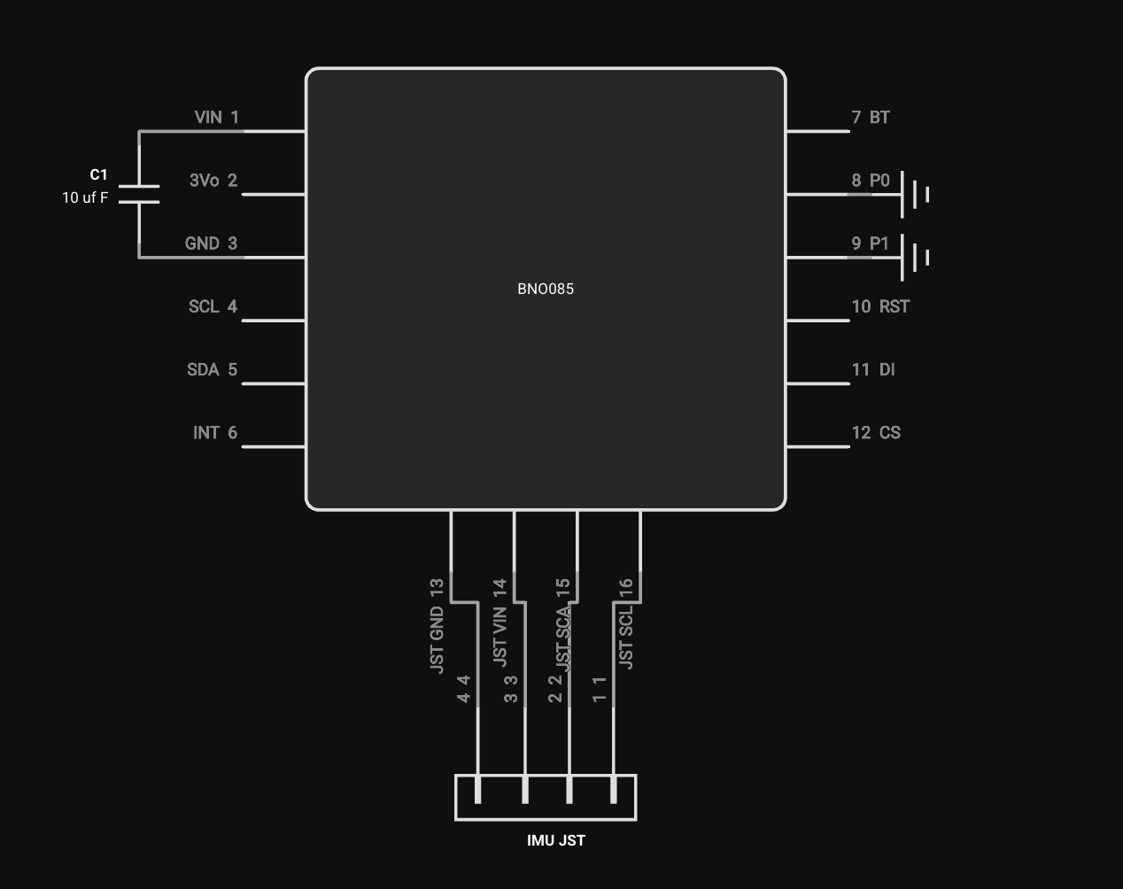
IMU

Motor Driver Protoboard
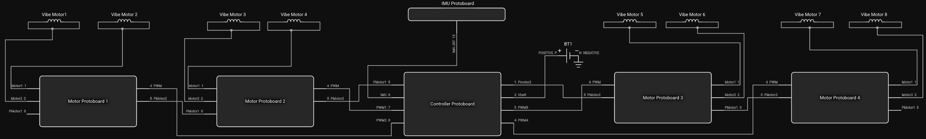
Functional electronics overview with multiplexed wires
Control and Software
The system software is divided into two sides: firmware running on the Particle Argon embedded controller, and a host-side Python stack running on a laptop.
Firmware Overview
The firmware is organized as a set of C++ modules, each encapsulating a distinct subsystem:
- HapticBelt: top-level orchestrator; owns all subsystems and drives the main loop.
- BeltBLE: BLE peripheral; receives threat packets from the host and transmits the current orientation quaternion.
- BeltIMU: interfaces with the BNO085 IMU over I2C; applies a configurable mounting-orientation correction at startup and recovers gracefully from any sensor resets.
- ThreatTracker: parses incoming BLE packets and maintains a list of up to 10 active threats; each threat slot is pre-assigned a unique haptic signature.
- HapticSignature: defines a temporal on/off vibration pattern (an array of switch times in ms) that distinguishes each threat slot by feel.
- MotorDriver: PWM abstraction for the 8 ERM motors at 500 Hz; maps motor index 0�7 to Argon pins {D5, A5, A4, A2, A1, D6, D8, D4}, with motor 0 corresponding to forward.
Main Loop Logic
Each loop iteration:
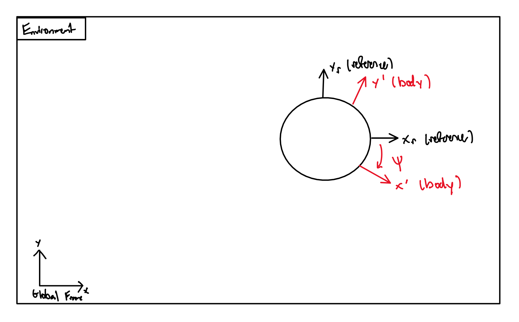
Diagram of Global vs. Body frame mapping logic. The
reference frame is calibrated to the world at startup
via a configurable initial orientation quaternion.
1. Reads the latest orientation quaternion from the BNO085 IMU and converts it to a yaw angle.
2. Calls ThreatTracker::update() to parse any newly received BLE threat packets and update the active threat list.
3. For each active threat, computes its target azimuth in global frame (-(atan2(y,x) � 180/π − 90�)), subtracts the current yaw to obtain a body-relative bearing, maps this to the nearest 45� motor sector, and scales motor intensity inversely with threat range.
4. If the threat's haptic signature is in its active phase, fires the corresponding motor via MotorDriver::triggerMotor().
5. Transmits the current orientation quaternion back to the host over BLE for visualization.
BLE Protocol
The belt advertises over BLE as "Argon Test". Communication uses a custom GATT service:
- Host → Belt: UTF-8 string of semicolon-separated threat packets: "[;id,x,y,z;...]". Setting z = -1 removes a threat.
- Belt → Host: Orientation quaternion as "w,x,y,z", sent each loop iteration.
Haptic Rendering and Threat Differentiation
Each of the up to 10 threat slots (IDs 0�9) is pre-assigned a unique haptic signature, a distinct temporal on/off pulse pattern defined in HapticSignature.h. When multiple threats are active simultaneously, each fires with its own rhythm, allowing the operator to distinguish between them by feel alone. Intensity is scaled from 10% (maximum range) to 100% (close range), giving an implicit sense of threat proximity.
Host-Side Simulation and GUI
The host-side Python stack (in v_env/) uses pygame for rendering and bleak for BLE communication. Two scripts are primarily relevant:
- gui_update_on_event.py: an interactive debug / user-introduction tool. Click to place threats, drag to reposition, right-click to remove. Displays a live sector-wheel visualization of motor mapping.
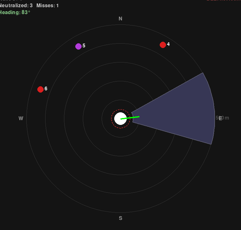
- brody_sim_main.py: the main demo simulation used during the live demo. Spawns spiral- and direct-approach threats across escalating waves; the operator must "neutralize" threats by facing them.
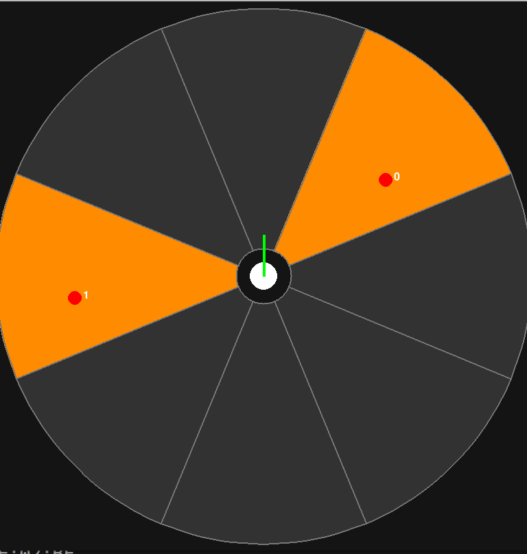
The host-side debug interface showing belt orientation,
instantiated threats, and sector differentiation.
The host-side simulation interface showing belt
orientation, active threats, and sector mapping.
For both, BLE telemetry packets are received and utilized to render the belt's current orientation, while threat info is broadcast back.
For additional information, please see the Github Repository!
System Analysis
While we were testing out our haptic belt, we noticed an interesting phenomenon. When we had the belt laying on the table and were testing our ERMs, it was very difficult to tell which ERM was vibrating; adjacent ERM mounts would vibrate with seemingly the exact same amplitude. This gave us a bit of a scare, as we thought when the user put on the belt they wouldn't be able to localize which ERM was vibrating. However, this turned out to not be an issue, as when we put on the belt, it was much more clear which ERM was vibrating. We wanted to do a dynamic analysis on this to see if we could replicate this phenomenon in a dynamic simulation.
Model description and assumptions
We are going to look at two separate, simplified dynamic models for the belt. Both models will only consider two separate motor housings, connected by a spring and damper to represent the connection via the belt. One of the masses will have an external sinusoidal force applied, representing the force from the ERM. We could in theory have added an extra degree of freedom and had simulated a rotating mass attached to one of our masses, but this would significantly complicate the analysis and likely produce the same result. We will compute an estimate for the erm horizontal force based on the ERM geometry and rotation speed. This is a good assumption as the acceleration of the much larger motor housing will be tiny compared to the attached rotating mass. Another reason this assumption is ok is that we are mostly concerned with input/output magnitude ratios for this analysis, and for a linear system this ratio is independent of the input magnitude.
Estimating F_erm
From the datasheet from a similar ERM, we can see that the steady state rotation speed of the ERM is 13000 RPM = 1361 rad/s [7]. The mass of the eccentric part is not given, but we will estimate it to be 0.5 g, with a rotation radius of 2.5mm. We can then calculate the centripetal force on the ERM to be (1361 rad/s)^2 * (2.5E-3)m * (0.3E-3)kg = 2.32 N. We will use this value as the amplitude of the applied sinusoidal force at a frequency of 1361 rad/s.
System descriptions

The first system will be "free floating" with no attachments to a grounded frame, representing the belt resting on the table, unconnected to a person. We could in theory add some damping to represent the friction of the table, however we are assuming the effect is negligible compared to the damping the human body will add.
k_b represents the spring constant of the belt, and d_b represents the damping constant.

The second model will be the same as the first, but each motor housing will also be connected to ground via a spring and damper, representing the belt being pressed into human skin.
k_h represents the spring constant of human skin, and d_h the damping.
Estimating k_h and d_h
To estimate the spring constant between the human skin and the motor housing, we made an estimate using a typical torsional Modulus of human skin (0.5 MPa)[8], and multiplied by the footprint of one of the motor housings against the skin, roughly 400 mm^2. This gives us k_h = 1000 N/m . To estimate the damping of the skin on the motor housing, we just observed that displacing the belt on the skin was clearly an overdamped system as it responds quite sluggishly compared to the amount of force applied to displace it, and there was no overshooting. So, we used a second order approximation with a damping ratio of 2 just as a rough estimate.
Getting an accurate estimate of the spring rate and damping of the belt is much trickier. The belt is made of nylon, which in theory has a very high tensile young modulus, however pure tensile loading conditions are not at all representative of how it behaves in this context, as the force transmitted from the ERM is not a pure tensile load. So, we are going to make the somewhat bold assumption that the belt connection has roughly 10x the stiffness of skin and is critically damped under a second order approximation (zeta = 1).
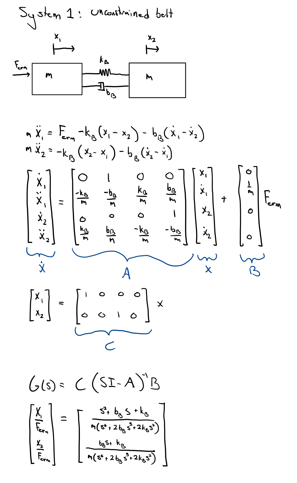
Deriving transfer functions for the systems:
See the work below for deriving the transfer functions for X_1/F_erm and X_2/F_erm for each system. A symbolic calculator was used to take the matrix inverse.

Simulation Results
Simulating the systems derived above to a sinusoidal input force with the equation: F_erm = 2.32*cos(1361*t) and plotting the response of x_1 and x_2, we obtain the following figures.

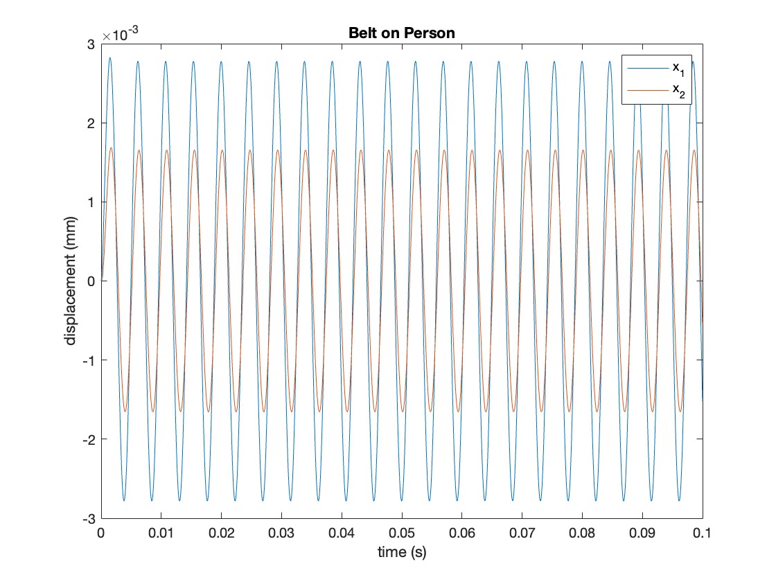
The first figure makes it clear that it would be very hard to distinguish whether the vibration force was originating from the first motor mount or the second, as the amplitude of the vibrations are nearly identical between the two motor housings. However, once each housing is constrained to a body, the vibrations for the second motor housing are cut in half relative to the the first, making it much easier to distinguish the origin.
In reality, the effect is likely even more dramatic, as the skin would be applying damping / removing energy from the vibration across the whole length between the two housings. Our idealized simulation above doesn't account for distance between the housings in any sort of way, though in practice it should have a big effect. This effect would be difficult to replicate and analyze without finite element analysis though.
Demonstration
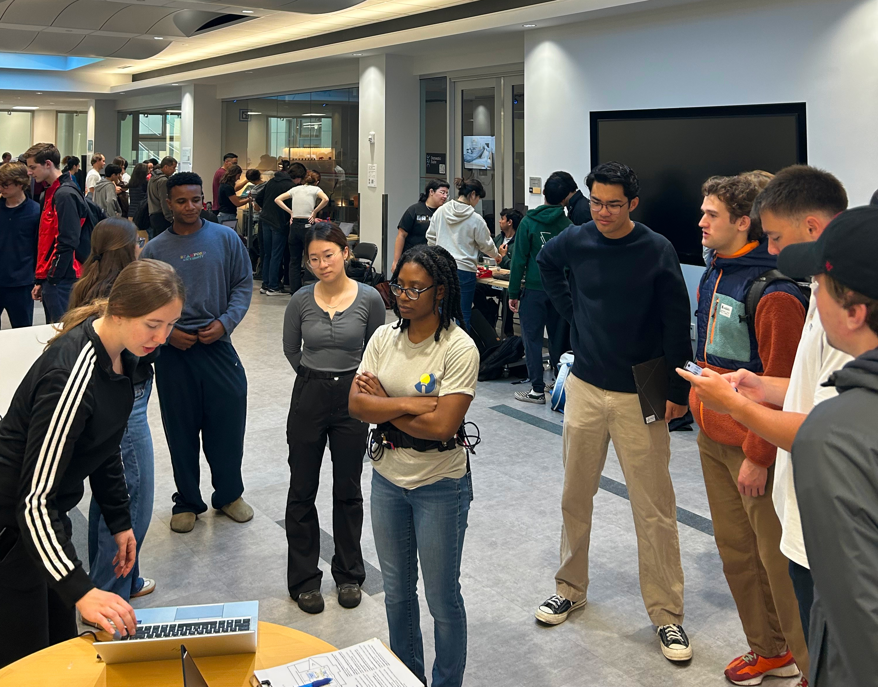
The Vibro-TACTical Belt attracting a crowd at the demo day.
We showcased this project at the demo day by first introducing users to the belt and its functionality, then allowing them to try utilizing the belt in a brief, fun, interactive simulation episode.
For each new user, we first adjusted the belt to their specific waist dimensions by adjusting the belt Velcro and re-positioning the vibration modules as needed. Our modular design allowed for quick re-positioning: the front buckle always held the front vibrator while the rear module always held the Particle board, IMU, antenna, and rear vibrator, so the other six modules were re-positioned as needed at 45 degree intervals. This process took no longer than a minute or two for each user.
Next, users were given a verbal and visual introduction to the system: we explained that the belt could render "detected threats" in the environment as haptic signals that came from a fixed global vector no matter how the user and belt re-oriented in the local frame. This explanation was accompanied by an interface where we moved the threat around a user and verified that they could feel the vibration from each module. Then, we kept the threat fixed while the user rotated in place to feel the feedback from a fixed direction. We also explained that when multiple threats are present in the environment, each one would be rendered with a slightly different haptic signature, with pulses offset slightly.
Finally, we launched an interactive simulation to give the users a chance to try using the belt in an interactive manner. The simulation consisted of a rendering of the belt orientation with an "awareness cone" radiating in the forward direction and randomly initialized "threats" which either move directly toward the user or spiral inward toward the user. The user's objective is to "neuutralize" all threats each wave by facing towards them for 3 seconds consecutively. Up to 3 threats were instantiated each wave, and the speed and number of threats were progressively increased from one wave to the next. Users were allowed to view the visual interface for the first wave to understand the objective, but only received haptic feedback for the subsequent rounds. While we did not collect exact performance statistics, with only this haptic feedback, most users neutralized at least 5/10, many neutralized 7-9, and one user successfully completed the entire task, a difficult task that not even the team themselves were able to accomplish!
The simulation interface.
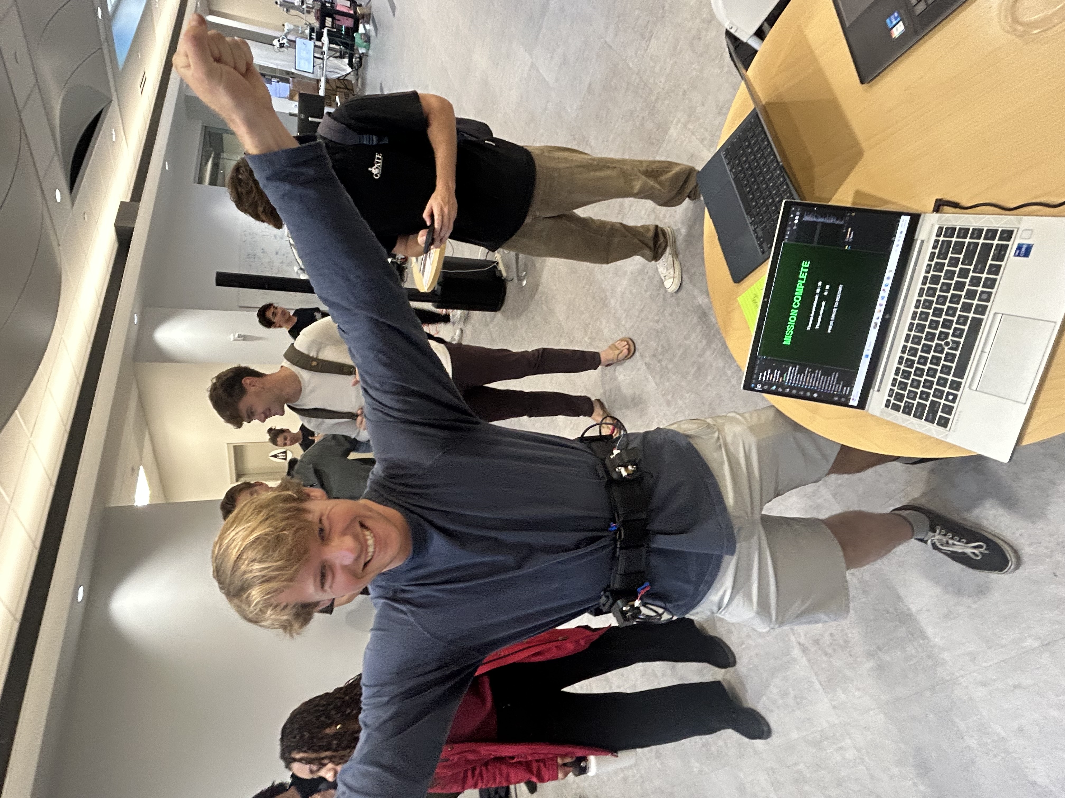
A successful participant!
Results
Brief feedback was collected from users who tried the system at the open house. Three questions were answered on a 5-point scale (1-5). Out of n=9 user testers, all 9 answered "5" to the question "How fun was the experience?," 8/9 answered "5" for the question "How noticeable was the haptic feedback?," and 7/9 answered "5" for the question "How helpful was the haptic feedback in completing the task?" The remaining responses for both of the latter two questions were "4"s. Clearly, the users were satisfied with the noticeability of the threat signals and felt that the belt was quite useful for localizing threats in the environment!
Future Work
While we were very happy with our initial prototype and demo, future work could extend this project even further. In terms of testing and analysis, we could attempt to validate our dynamic analysis of the system and more exactly quantify the impact of damping when mounted to the human body. This would allow for more precise tuning of appropriate vibration amplitudes and perhaps inform the material selection for future iteration with a custom-designed belt rather than an off-the-shelf work belt. Additionally, we could carry out a discrimination analysis similar to [6] to generate a confusion matrix between pairs of motors, which could be relevant if testing different types of haptic cues and ensuring that neighboring cues can be resolved as separate.
In terms of specific system improvements, one idea is to incorporate additional useful haptic signals without overwhelming the user. For example, an indication (three quick pulses) could be delivered to an appropriate vibration module when a threat is first detected. Our existing range-based rendering algorithm can make it difficult to sense new threats until they are closer to the user even if they are detected when they are at the outer limits of the device's range, so such a pulse could provide a user with a useful indication that there is a new threat present.
Finally, the initial promise of this haptic rendering of threat information could be integrated with a wider covert detection system. Work is ongoing to develop a passive, acoustic threat detector which could generate threat vectors in a live environment (rather than simply simulating such threats directly). The Vibro-TACTical Belt offers a quiet, low-profile, covert means of delivering such information to an operator without overwhelming them with a visual or audible signal.
Acknowledgments
Thank you to Megan Coram for helping us with our initial project proposal and Prof. Allison Okamura for assisting with project scope!
Files
Github Repository: https://github.com/AndrewPasco/me327-proj.git
- STLs of custom components found at https://github.com/AndrewPasco/me327-proj/tree/main/CAD
List of Major Components: https://docs.google.com/spreadsheets/d/1R6oqXomNVhh760MuiCMAZUMMv0IkrRH8FH-eOSOXCVs/edit?usp=sharing
References
[1] U.S. Department of Defense. Fact Sheet: Strategy for Countering Unmanned Systems. 5 Dec. 2024, https://media.defense.gov/2024/Dec/05/2003599149/-1/-1/0/FACT-SHEET-STRATEGY-FOR-COUNTERING-UNMANNED-SYSTEMS.PDF.
[2] Erp, Jan BF Van, et al. "Waypoint navigation with a vibrotactile waist belt." ACM Transactions on Applied Perception (TAP) 2.2 (2005): 106-117. https://doi.org/10.1145/1060581.1060585.
[3] Elitac Wearables. Mission Navigation Belt. Elitac Wearables, https://elitacwearables.com/projects/mission-navigation-belt/. Accessed 23 May 2026.
[4] Engineering Acoustics, Inc. ETSAS (Enhanced Tactile Situational Awareness System). Engineering Acoustics, Inc., https://eaiinfo.com/etsas/. Accessed 23 May 2026.
[5] Kim, J., Park, J., Park, C., Park, J., Choi, S. (2025). Human Identification Performance of Vibrotactile Stimuli Applied on the Torso Along Azimuth or Elevation. In: Kajimoto, H., et al. Haptics: Understanding Touch; Technology and Systems; Applications and Interaction. EuroHaptics 2024. Lecture Notes in Computer Science, vol 14768. Springer, Cham. https://doi.org/10.1007/978-3-031-70058-3_1.
[6] K. C. Stovicek, S. T. King, E. D. Z. Chase, J. J. Fleck, P. Zandiyeh and M. K. O'Malley, "Walking does not Diminish Localizability of Vibrotactile Feedback on the Waist," 2025 IEEE World Haptics Conference (WHC), Suwon, Korea, Republic of, 2025, pp. 492-498, doi: 10.1109/WHC64065.2025.11123181.
[7] JIE YI Electronics Limited, �JYC1027,� DigiKey Electronics. [Online]. Available: [https://www.digikey.com/en/products/detail/jie-yi-electronics-limited/JYC1027/20193265](https://www.digikey.com/en/products/detail/jie-yi-electronics-limited/JYC1027/20193265). Accessed: May 31, 2026.
[8] M. Pawlaczyk, M. Lelonkiewicz, and M. Wieczorowski, �Age-dependent biomechanical properties of the skin,� _Advances in Dermatology and Allergology/Postępy Dermatologii i Alergologii_, vol. 30, no. 5, pp. 302�306, 2013, doi: 10.5114/pdia.2013.38359.
Appendix: Project Checkpoints
Checkpoint 1
In Checkpoint 1, we successfully established a prototype virtual environment with an associated GUI to set threat positions relative to the user, the hardware communication backbone, and the core state estimation logic. On the software side, this included a modular control framework abstracting the IMU, BLE, and haptic drivers; a global-to-body frame mapping implementation using a zeroed local calibration scheme; and a simulation environment representing multiple simultaneous drone threats across eight discrete radial sectors. On the hardware side, the team selected the BNO085 IMU with UART-RVC protocol to resolve I2C clock-stretching issues on the nRF52840, finalized PWM pin assignments for all eight ERM motors on the Particle Argon, completed electrical schematics for all subsystems, and implemented the BLE communication structure for bidirectional exchange of IMU heading and threat position data between host and agent.
Goals Met:
- IMU Integration: Identified the BNO08x as the optimal sensor and selected the UART-RVC protocol to ensure robust 100Hz orientation data without the I2C "clock stretching" issues common to the ESP32/nRF52840 families.
- Software Architecture: Designed a modular controller that abstracts the IMU, BLE, and Haptic drivers, allowing for parallel development.
- State Estimation & Mapping: Implemented the core logic to normalize absolute IMU yaw into a relative reference frame and map threat azimuths to the 8-motor array.
- Hardware Mapping: Finalized the pin assignments for the Particle Argon, ensuring all 8 motors are on dedicated hardware PWM pins.
- Virtual Environment GUI: Built a working prototype GUI that simulates the yaw of a person wearing the haptic belt and allows the user to place drones relative to the user. It can place and remove multiple drones and sends information about which motor should activate and at what duty cycle based on the drone�s relative distance from the person.
Challenges: One challenge discovered was an I2C bug present with the nRF52840 (in our selected controller). Fortunately, the selected IMU supports UART-RVC, which actually simplified our code and increased system stability. Another challenge is that in the current virtual environment implementation, there is no communication regarding the number of drones in one of the discrete sectors around the wearer. The vibration is currently set to a duty cycle corresponding to the distance of the nearest threat in that sector, so additional work will be done to experiment with how multiple threats can be conveyed from the virtual environment to the vibration controller.
Updated Plans: We have decided to focus on a combination of global and local calibrated frames (by zeroing the belt) to ensure that the haptic cues are intuitive even if the belt is put on slightly crooked. This will also allow us to send threats from the host in a global frame, then map these to the local frame.
Hardware: The haptic belt will be built on a commercial adjustable triathlon-style belt which is slim, elastic, and has the ability to sit flush against the body for comfort and covertness. The belt sits tight to the body and can be worn covertly under a user's clothing without adding significant bulk.
Motor mounting will be achieved via eight custom 3D-printed clips, modeled after the open belt clips used on military uniforms. Each clip will be designed to slide and lock onto the triathlon belt, allowing repositioning along the belt's length so that the ~45� angular spacing between motors can be maintained regardless of the wearer's waist circumference. A 3D model of the open belt clip is shown below. The interior face of each clip will house one ERM coin motor, covered with a thin lycra or neoprene patch to ensure consistent skin contact and comfort during wear. Clips will be printed in PETG or TPU to provide the necessary durability and slight flex for body-conforming fit.
Each motor clip is wired independently back to the central electronics module via a dedicated wire, with small slack loops routed along the belt between clips to accommodate repositioning without wire binding. The central module, which will house the Particle Argon, LiPo battery, and motor driver breakout boards, is contained in a small 3D-printed pouch enclosure velcroed to the belt at the small of the back, keeping the system's mass centered and low-profile.
Electronics
1x 200 uF cap 4x 100 uF caps 4x 20 uF caps 1x 10 uF cap 5x 0.1 uF caps
1x 10k resistor
8x ERM
4x Adafruit DRV8833 DC/Stepper Motor Driver Breakout Board
Jst-sh 4-pin wire (For IMU connection)
Particle Argon Controller (already owned)
The PRL has an assortment of protoboards and molex connectors that we will use.
- Schematics
Note that this top level schematic uses multiplexed wires, motors aren't actually connected to one wire. View the individual schematics for the breakouts.
High Level Schematic:

Controller Protoboard Schematic:
IMU Protoboard Schematic:

Motor Driver Protoboard Schematic:
- Motor communication protocol / wiring scheme / controllers as needed
Developed schematic to use I2C, but we may be switching to a serial protocol to avoid clock issues
- Identification of appropriate communication protocol from �host� to �agent�
Bluetooth Low Energy (BLE)
- IMU identification
Adafruit 9-DOF Orientation IMU Fusion Breakout - BNO085
Threat Virtual Environment and GUI: The prototype virtual environment runs on PyCode and allows a user to easily place and remove multiple drones with a click on the GUI. It is currently simulating the yaw of the person wearing the belt, controlled by keyboard commands for rotation to the left and right. This setup divides the free space around the user into eight equally large discrete radial sectors, each corresponding to one of the eight vibration motors we have proposed on the belt. When a threat is placed using the GUI, the current setup communicates the sector number and a relative intensity recommendation for the duty cycle of the motor that corresponds to that section. To match the hardware board that the team selected, the current virtual environment has code for BLE communication back and forth for IMU heading data and threat number and position data. The hardware/software integration will be attempted by Checkpoint 2.
Prototype Threat GUI Video: https://youtube.com/shorts/4py1CZDAsaI?feature=share
Checkpoint 2
In Checkpoint 2, we focused on refining the `belt_controller` software and preparing our hardware mounting strategy. On the software side, we prepared the main code to test the BNO085 IMU upon its arrival, wrote code to control the motors with the DRV8833 drivers once they arrive, integrated previously tested BLE communication code into the main control loop, and continued to refine the host-computer GUI for adjusting and rendering the environment. On the hardware side, we designed a few custom 3D-printable buckles / housings to facilitate adjustable mounting of the ERM vibration motors, motor drivers, main microcontroller, and IMU.
We ordered all our required ICs last Thursday, and unfortunately shipping delays have pushed back our schedule for assembling a prototype and implementing our code. The motor drivers and IMU should be arriving by the end of today (5/21). However, we made significant progress in our code and made a major rework to the code architecture to make managing and debugging much easier once we have the hardware to test.
Goals Met:
- IMU and Control Prep: Made significant alterations to the main code in the `belt_controller` to support the BNO085 IMU. We introduced logic to handle multiple active threats concurrently and added the UART-RVC library locally since Particle did not support importing it.
- BLE Integration: Integrated our previously tested BLE communications code into the main loop, replacing the simulated serial inputs and allowing the controller to receive dynamic threat updates (with unique target ID and matching global coordinates) from the host virtual environment over a robust wireless architecture. Made the virtual environment more robust with a drag and drop feature and individual target clearing.
- Hardware Mounting: Designed a custom 3D-printable buckle that attaches to commercial belt keepers we ordered online. This design allows for flexible, adjustable mounting of the ERMs and motor drivers around the circumference of the belt, ensuring consistent skin contact and comfort. Additionally, we designed a housing for the front, main buckle, which will hold the IMU and main microcontroller. Finally, preliminary belt prototypes were sewn from test fabric and are ready for housings to be attached.
Challenges: While waiting for the physical IMU to arrive, we've had limited opportunities to test software beyond the BLE comms. We anticipate needing to fine-tune the PWM intensities and threat mapping logic once the hardware is fully assembled and we can evaluate the ERM spin-up/spin-down and different haptic icons.
Updated Plans: With the core control loop and BLE integration in place, our next focus will be physical integration. Once the IMU arrives, we will validate the UART-RVC data stream and compare with an I2C approach, then use the incoming data from the IMU to fine-tune our state estimation algorithm and threat rendering methodology. We will soon begin printing the newly designed buckles and assembling the full 8-motor array on the belt for user testing.
Updated Threat GUI Video: https://youtube.com/shorts/_59D4u1_2iQ?feature=share