

2026-Group 15
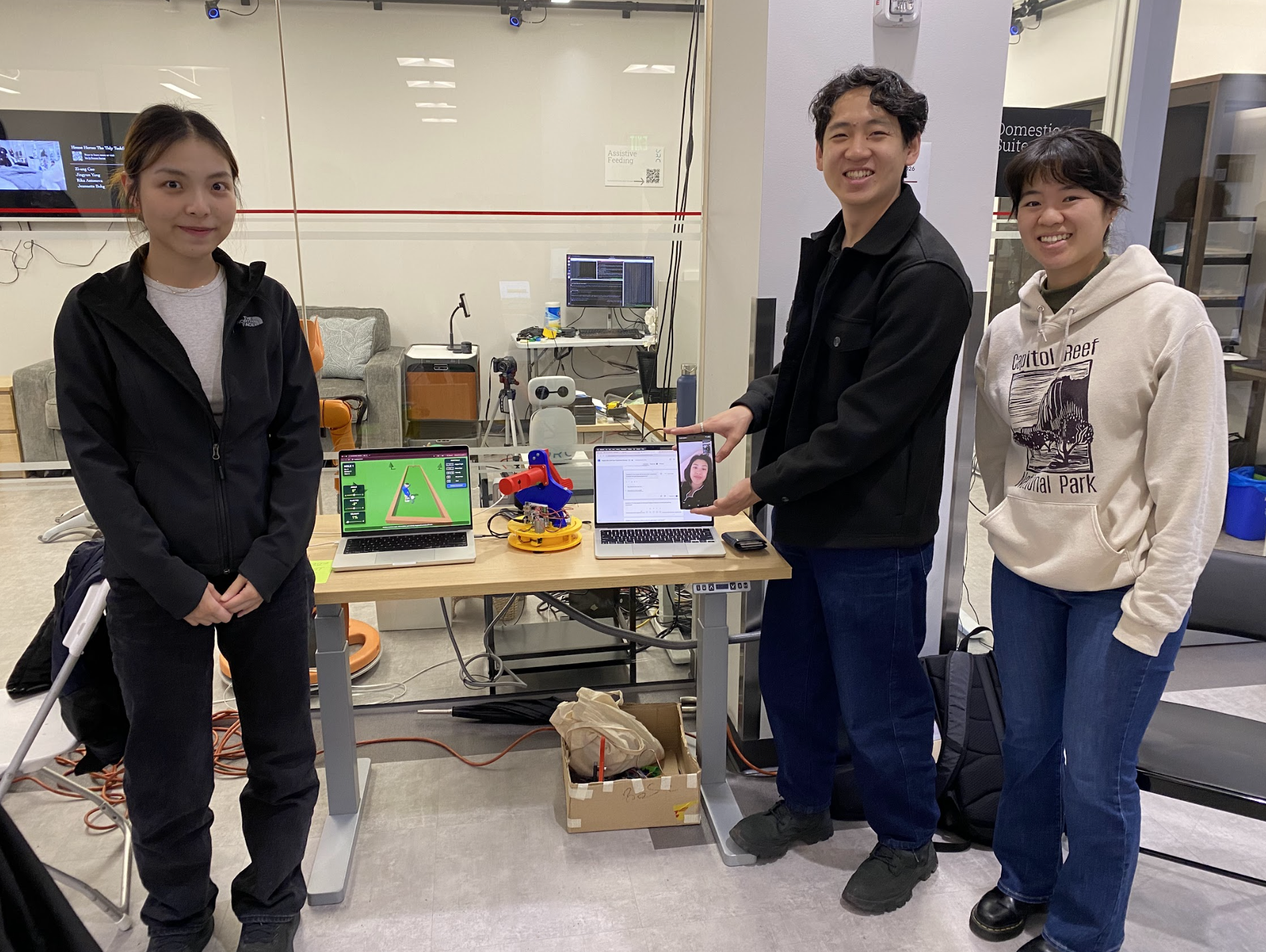
Figure 1:
Group 15: Mini-Golf Haptic Interface
Mini-Golf Haptic Interface
Project team member(s): Risa Xiang, Anna Yu, Ariel Wang, Harbour Li
The Mini-Golf Haptic Interface project was developed to create an engaging and immersive virtual mini-golf experience that combines realistic physical interaction with interactive gameplay. Motivated by the team's interest in enhancing a familiar game through haptic technology while applying concepts from ME327: Design and Control of Haptic Systems, such as robotics, kinematics, controls, and virtual environments. The project aimed to design a two-degree-of-freedom desktop handheld haptic device capable of providing both kinesthetic and cutaneous feedback. The final implementation featured a custom 3D-printed capstan-driven mechanism with two revolute joints for aiming and swinging, dual motor-based force feedback, integrated vibration motors for cutaneous impact sensations, and a nine-hole virtual mini-golf game that responded to the user's motions in real time. Through iterative mechanical, electrical, and software development, the team successfully integrated motion tracking, force rendering, vibration feedback, and graphical simulation into a cohesive system. User testing during the final haptic open house demonstration showed overwhelmingly positive results, with participants reporting high levels of enjoyment, realism, and immersion, demonstrating that the project successfully achieved its goal of creating a fun, intuitive, and effective haptic gaming experience.
On this page... (hide)
Introduction
For this project, we have chosen a specialized handheld desktop device with two revolute joints to match the pivot and the swing of a golf simulator, as well as a vibration motor and virtual environment to give users both kinematic and cutaneous feedback for an interactive and interactive gaming experience. Our motivation for this implementation was to build something fun and elevated a game that we were familiar with, Game Pigeon Mini Golf. In addition, we chose to pursue this project due to its broad coverage of this course topic, from manipulator kinematics to interactive virtual environments, as well as the practicality of the project.
Background
Recent developments in haptic interfaces and virtual interaction systems have demonstrated the effectiveness of combining motion tracking, force feedback, and immersive simulations to improve user interaction and motor learning. Prior research in golf-training devices and haptic rendering influenced the design of this project, particularly in the areas of real-time feedback and interactive virtual environments.
Basdogan and Srinivasan [1] established many of the foundational principles behind modern haptic systems through their work on haptic rendering in virtual environments. Their research explains how collision detection, force-response algorithms, and high-frequency haptic loops create more realistic touch interactions in digital spaces. Their paper also highlights the role of haptics in training and skill development by providing tactile feedback alongside visual interaction. These concepts helped with our integration of a virtual mini-golf environment with synchronized physical feedback to create a more immersive user experience.
Referencing a paper that focuses on golf swing realism, Nakamura and Koike [2] developed a golf club-type haptic device that provides real-time force feedback to guide a user�s swing posture. Their work addressed limitations in traditional golf training where feedback is often delayed through video review or verbal coaching. Using a gyroscopic force-feedback mechanism integrated with a simulation environment, the device allowed users to receive immediate correction and feedback while maintaining natural motion. Though our project is extremely simplified, we used this research to provide context in how other systems modeled virtual impacts and collisions with vibrations.
In the same vein of feedback in golf-related applications, Tekriwal and Sharma [3] developed GolfGuide, an assistive system for visually impaired users. Their device combined motion sensing with vibration and auditory cues to help users improve swing mechanics and ball alignment. This project showed how compact embedded systems and real-time feedback can effectively support user interaction and motor learning. Within our project, we use spring and damper feedback as well as vibration to strengthen user engagement with the golf simulation.
Together, these papers gave us a great foundation of our haptic mini-golf simulator by demonstrating how real-time tactile feedback and virtual interactions can create more engaging and intuitive gaming experiences.
Methods
Throughout the course of this project, we constantly iterated the hardware and electrical design of the device as we evaluated the effectiveness and reliability of different components. Most notably, the original concept of the device included two optical encoders fitted with the two motors. After designing and much experimenting to implement the optical encoders reliably with the rest of our system, the encoders were deemed just a bit too finicky and unreliable for the time, scope, and practicality of the project. The description of methods following describe the iterative process of designing our system from the initial to final concepts.
Hardware Design and Implementation
The Haptic Mini Golf device was designed as a two degree-of-freedom haptic interface that enables users to control both the direction and strength of a virtual golf shot while receiving kinesthetic and cutaneous feedback. The system consists of two orthogonal revolute joints and a user handle, which naturally divide the device into three primary subsystems: the base subsystem, the tower subsystem, and the human interface subsystem. The overall architecture was inspired by the 3D Systems Touch haptic device used throughout this course, where the primary structure is mounted on a rotating base. This configuration eliminates the need to route electrical wiring through multiple moving joints, reducing both mechanical complexity and cable management challenges.
To provide smooth and responsive force feedback, both degrees of freedom utilize capstan drive transmissions. Capstan drives are well suited for haptic applications because they offer efficient torque transmission with minimal friction and backlash, resulting in improved transparency and control fidelity. These design choices simplified the system dynamics while providing a clear framework for the development of each subsystem.
The base subsystem forms the first degree of freedom and consists of a stationary base and a rotating chassis. The base anchors the device to the ground and serves as the driven pulley of the capstan transmission, while the chassis supports the first motor, the electronics, and the tower subsystem. Because the base is fixed relative to the ground, the motion of the chassis relative to the base directly defines the first joint angle. The tower subsystem forms the second degree of freedom and consists of a structural tower and a sector pulley that supports the human interface. This subsystem provides the swinging motion used to strike the virtual golf ball. The human interface subsystem consists of an ergonomic handle containing two eccentric rotating mass (ERM) vibration motors and a miniature golf club attachment that provides an intuitive visual and physical representation of the virtual interaction. All major structural components were manufactured using PLA through additive manufacturing, enabling rapid prototyping and iterative design refinement. Standard hardware and electronic components supplied by the Stanford PRL and ME327 Haptics Laboratory were used for assembly and integration.
The final system incorporates two capstan drive mechanisms, two DC motors for kinesthetic feedback, two ERM motors for cutaneous feedback, a single Hapkit controller board, and two magnetic rotary (MR) sensors for position measurement. Throughout development, the design underwent several iterations as mechanical, electrical, and software requirements were refined. The most significant architectural change was the replacement of the original optical encoders with MR sensors. Although optical encoders offered higher theoretical angular resolution, integration difficulties and inconsistent performance within the prototype led the team to adopt MR sensors. The transition simplified sensor mounting, reduced mechanical complexity, improved reliability, and required modifications to the base structure and cable routing strategy.
The human interface subsystem also evolved considerably during development. In the initial concept, the handle was mounted at the end of the golf club linkage, which resulted in less intuitive wrist motions during operation. In the final design, the handle was relocated to the rotational axis of the sector pulley, creating a user experience more similar to operating a foosball handle. This modification improved ergonomics, simplified assembly, and provided a more natural mapping between user motion and the virtual golf swing. Together, these design refinements resulted in a compact, robust, and intuitive haptic interface capable of delivering realistic force and vibration feedback while maintaining smooth, low-friction motion.
Base Subsystem
The two main component of the base subsystem is the base and the chassis, their design address the needs which are identify in the determination of the system architecture.
The main function of the base is to provide a stable and robust revolute joint interface between the ground and chassis, this natural extended to the following features:
1. A set of feet/leg to distribute the weight of the device evenly and maintain balance and good contact with the ground during usage
2. A strong revolute axis
3. A circular feature that serves as the pulley for the chassis to rotate
4. Anchors for the string on the capstan drive
5. To provide a datum for future calibration, a pointer tower extending to the height of the chassis can provide sufficient reference for the angle between the base and chassis
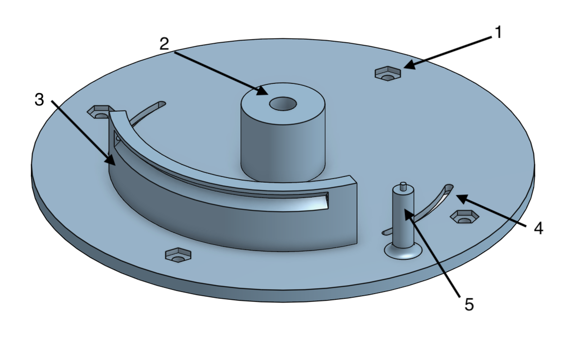
Figure 2: Final base design
In addition of being the first joint the chassis is essentially a support platform for the second joint and any electrical components, its designed included the following features:
1. Connection to the shaft from the base
2. Connection to the motor for the first joint
3. Connection to the tower subsystem, including two square 4-way-locator and two holes for heat set insert and fastener
4. Connection point for hapkit control board
5. Additional holes for wire connection and wire managements
6. Slot and graduations the pointer tower on the base

Figure 3: Final chassis design
The initial design adopted maxon motors and optic encoders, however, through debugging the optical encoder was found faulty and the motor had a large internal resistance. This prompted the design change to adapt the Mabuchi motor from the hapkit and a magnetoresistive sensor, and the sensor is mounted on a bracket that extended downward and enclosed the far end of the motor shaft where a magnet is mounted.
The main components of the final subsystem assembly includes the following:
1. The base
2. The chassis
3. The Mabuchi motor
4. The magnetoresistive sensor holder
5. The hapkit board
6. The shaft pulley and magnet
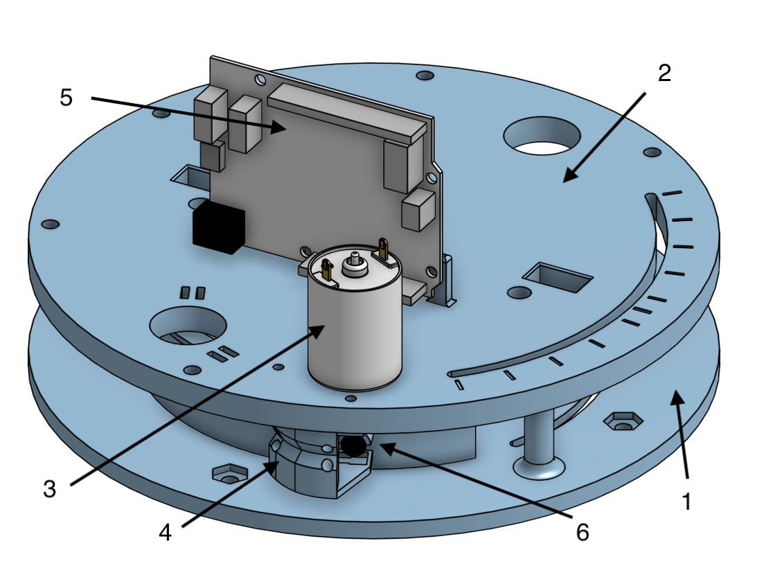
Figure 4: Final base subsystem assembly
The first joint featured a rotational range of 90 degrees that match the typical range of motion of the wrist and elbow joints in a horizontal plane. For calibration purposed, the angle of the chassis with respect to the base is denoted but the pointer in the slot. The base has two shaft collars in the hub and uses a shoulder screw as the rotation axis and connector with the base. Four rubber suction cups are used to anchor the haptic device.
Tower Subsystem
The tower and sector pulley system work together to facilitate the swinging DOF of the golf club. The tower supports the central axis of the motion with a strong and modular attachment to the base chassis. This allows the team members to prototype the two sub-systems separately and iterate quickly. The sector pulley converts the motor force into a handle torque via a neoprene capstan drive. The final sector pulley spans 120 degrees to allow for ample user wrist flick motion. The height of the swing origin to the base chassis is set to 125mm to adjust to the fit of the mini golf club without any clashes. The radius of the sector pulley is 95mm, which is a larger gear reduction than selected for the Hapkit to allow for higher torque reduction of the motor to achieve more realistic virtual wall sensations when hitting the golf ball. The mounting of the sector pulley to the tower uses the same delrin sleeve bearing and shaft collar on shoulder screw as used in the Hapkit, and print tolerances were adjusted for fit. Figures 5 and 6 show the various mounting interfaces added to the structure to join with other subsystems such as the mini golf club, the haptic handle, the motor, and the base chassis. All used bolted interfaces, but the base chassis also used a slotted dovetail design to reinforce the strength of the connection as the base joint would feel the most torque when the user is adjusting the angle of the club.
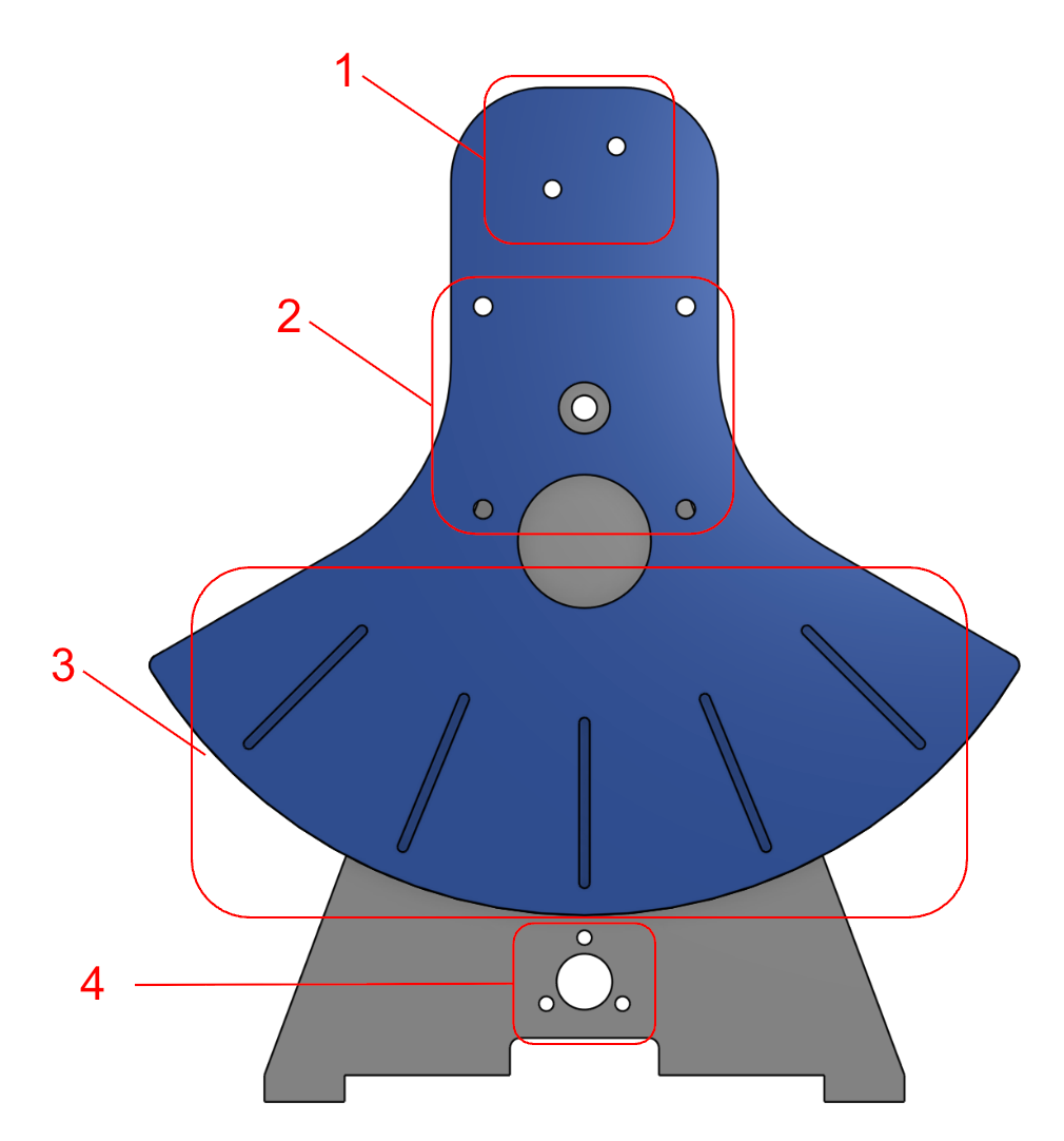
Figure 5: Final tower system front
1. Golf club mounting holes
2. Haptic handle mounting holes (centered about swing origin)
3. Swing angle indicators (22.5 degrees apart)
4. Motor mounting holes
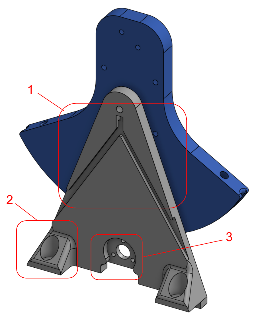
Figure 6: Final tower system back
1. Vibration motor wire routing channels
2. Dovetail joints for mounting to chassis
3. Motor mounting holes
One example of an integration challenge with the tower sub-system early on is where to place the capstan motor. The motors themselves were relatively large compared to the size of the device and there were two motors and the Arduino board to fit into space unoccupied by the swinging motion of the club. Initially, the idea was to maximize the space for the user interface by jamming all the motors to one side of the tower. This posed a problem where the chassis and tower motors would clash into each other and the Arduino board, and an offset L-bracket had to be grown off the side of the tower to support this cantilevered motor. Instead, we opted to mount the tower motor on opposite sides to the chassis motor and reducing the length of the club such that its swing would clear above the tower motor. This design choice maximized the usable space on the device and also helped maintain an equal distribution of mass, which greatly improves the smoothness of the base chassis rotation!
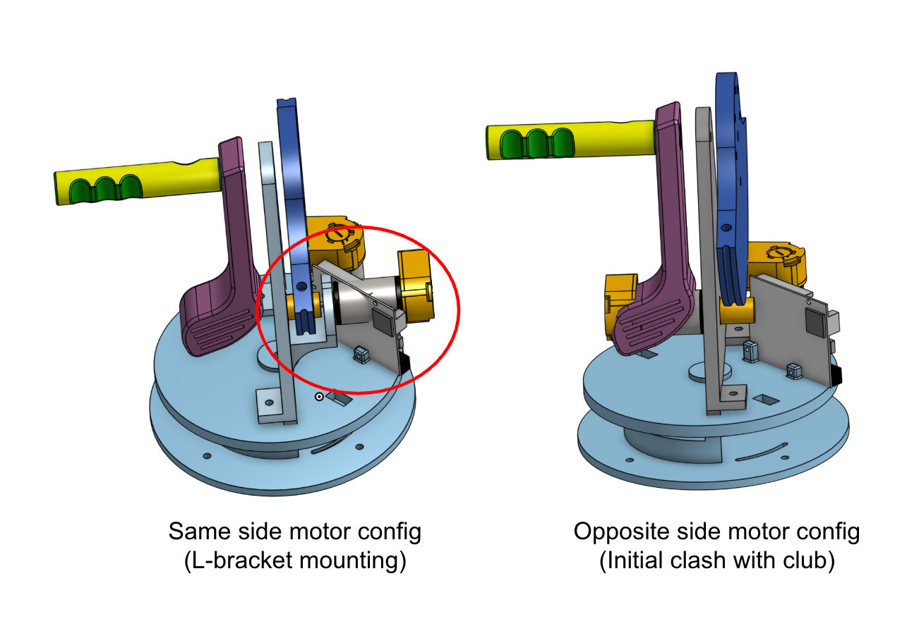
Figure 7: Early iteration of tower motor configurations
Humand Interface Subsystem
The golf club and user handle were designed as separate components that are independently mounted to the sector pulley of the handle capstan drive. Although they are not rigidly connected to each other, both components rotate together with the sector, allowing user inputs to be directly translated into the virtual golf swing. This configuration was selected to create a more intuitive and realistic interaction while providing greater flexibility in the mechanical design and assembly process. The orientation and placement of the golf club relative to the user handle were chosen to emulate the experience of swinging a real golf club, enabling users to naturally control the direction and strength of each shot.
The user handle was ergonomically designed to accommodate two eccentric rotating mass (ERM) vibration motors for haptic feedback. One ERM is positioned near the thumb contact area, while the second is located beneath the remaining fingers. This arrangement distributes vibration feedback across multiple contact points on the user's hand, increasing the perceived intensity and realism of impact events during gameplay. To support the integration of the vibration motors, a dedicated cable-routing channel was incorporated into the underside of the handle. This feature allows the ERM wiring to be neatly routed through the assembly while preventing interference with the user's grip and handle motion. The resulting design provides a clean assembly, improved cable management, and enhanced haptic feedback delivery.
The human interface and the tower subsystem forms the second capstan drive.
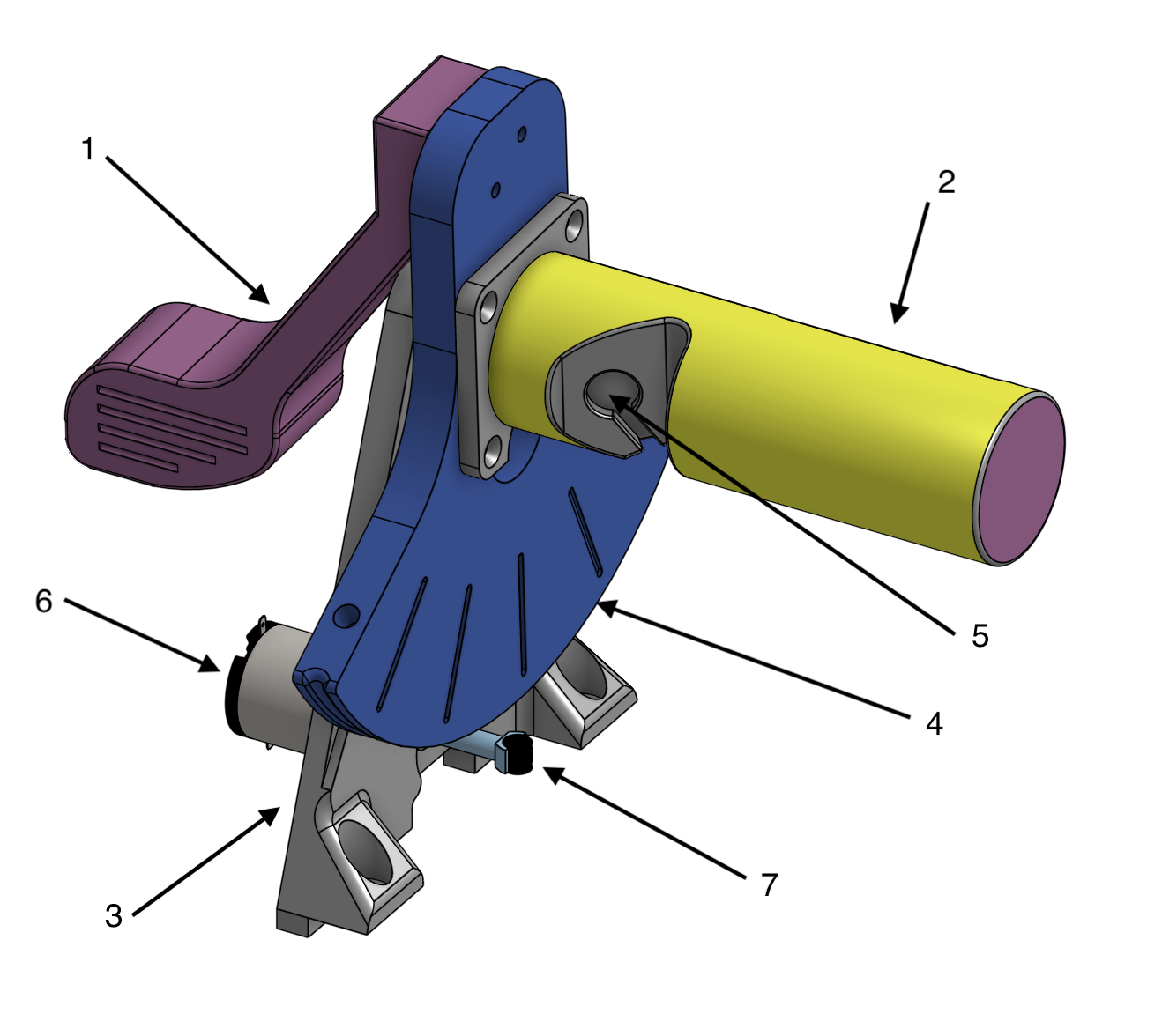
Figure 8: Human interface and tower subsystem
1. Golf Club
2. Handle
3. Tower
4. Sector pulley
5. ERM motor mount
6. DC motor
7. Magnet
Final Device
In the CAD software the tower and the human interface subsystems are attached to the base to form the completed CAD of the device
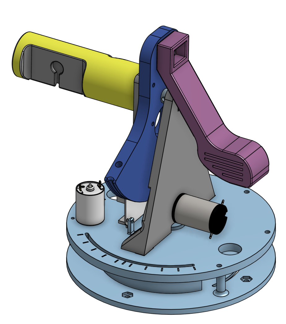
Figure 9: Completed CAD
The six main piece of the mini golf haptic device are printed with PLA with infill setting of 10%. Heat set inserts are added to the chassis and the sector pulley to facilitate hardware connections. The strings are installed via attaching one end to the sector pulley, then loop over the motor pulley and attach the other end to the sector pulley. Metal weights are added to the chassis to balance it out during rotation.
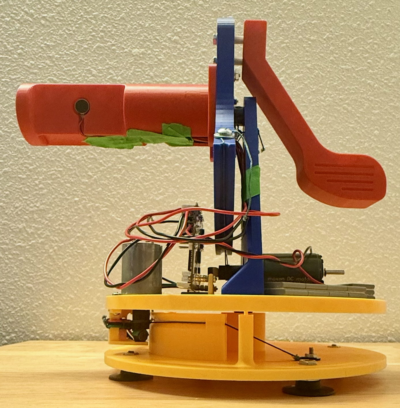
Figure 10: Completed device
Electrical Interface and Wiring
Initial
Initially, the electrical interface was designed to support the integration of two DC motors, two optical encoders, and one ERM motor. Based on the power, signal, and input/out requirements of each component, the Hapkit board, supplemented with a micro breadboard, was determined to provide sufficient interfacing capability for the complete system.
Each DC motor input was connected through the screw terminal outputs of the onboard L298 motor driver, enabling bidirectional motor control. The corresponding PWM and DIR control signals for each motor were assigned to dedicated digital output pins on the Hapkit board.
For positional sensing, a HEDL-5560 and a HEDM-5500 optical encoder line driver was implemented. The HEDL encoder interfaced through a 10-pin IDC ribbon connector, though only five essential pins were required for power, ground, and signal transmission. The HEDM encoder had 5 male pins that can be wired to the breadboard. Both encoders operate as a three-channel incremental encoder, providing channels A, B, and I (index) for accurate rotational tracking and direction detection. To ensure reliable encoding performance, 2.7 kΩ pull-up resistors were added to each signal channel. An external breadboard was allocated to simplify routing and maintain signal integrity. The power and ground connections from the encoders were routed directly to the corresponding outputs on the Hapkit board.
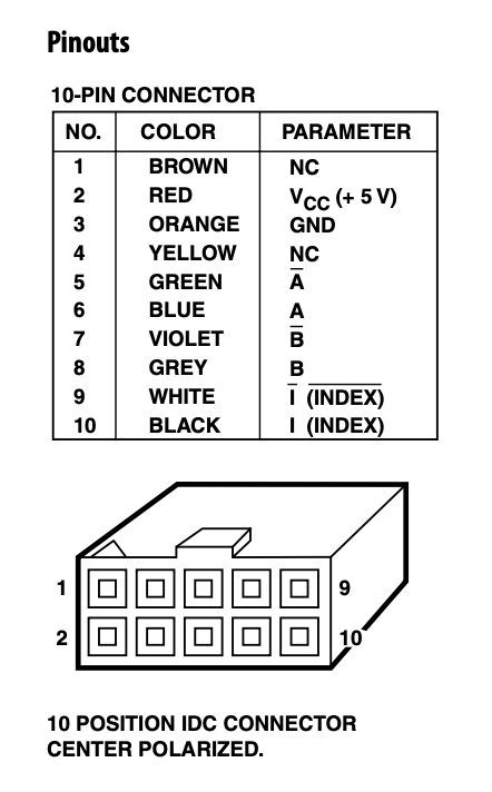
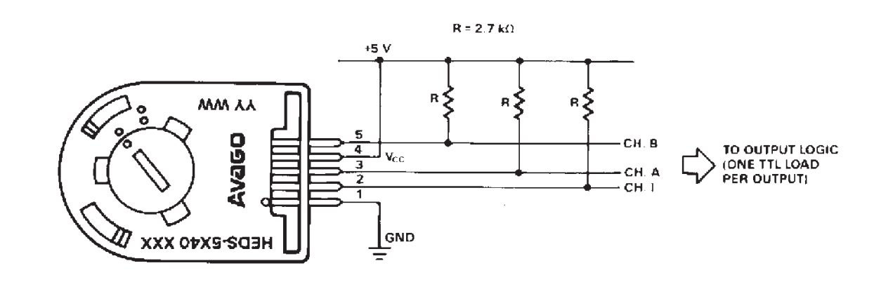
Figure 11: HEDL optical encoder pin callouts and electrical interface
The ERM motor was connected using a PWM-enabled digital output and ground connection on the Hapkit board.
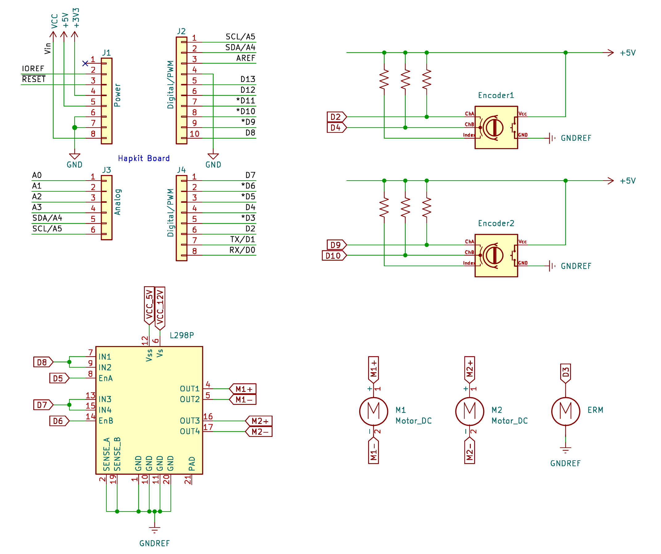
Figure 12: Initial schematic to include encoder components
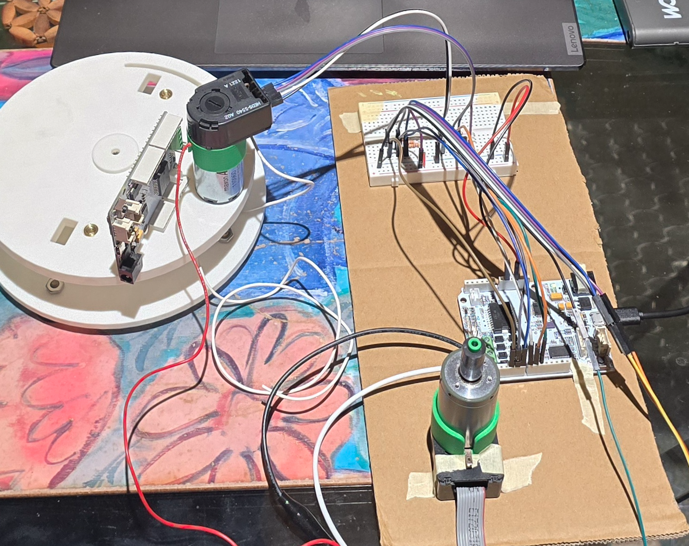
Figure 13: Encoder wiring to test components
After connecting all leads and pins and a significant amount of time experimenting with the outputs of the encoders, a waveform was able to be generated and numbers outputted from the encoders, but the combination of motors and encoders was deemed too noisy and inconsistent for our project's use case. As there is a need to detect small angle displacements at, frequently, a larger velocity, we noticed frequent slipping where the waveforms would not catch all of the positional changes inputted into the system. In addition, there was a lack of consistency and reliability in the system. Performing a simple test of moving the handle a certain degree then bringing it back to zero, the output would not show that it has returned to its zeroed position. With the gathered knowledge and experience, we discussed future steps, moving towards systems and components that we have worked with before and have proved to produce reliable results in the past.
Final
A decision was made to swap the two optical encoders to two MR sensors: one in which was already soldered onto a Hapkit board and the other off-board. Moving this MR sensor off-board reduced spatial constraints of where the Hapkit board needed to be and reduced the need to use another board. Electrical connections between the sensor and control board were extended using soldered wire leads, allowing the sensor to be mounted independently. Already having experience with wiring two encoders to the Hapkit board, wiring an additional MR sensor proved to be simpler as there was no need for a pull up bridge for reliable angle readings. We were able to completely pare down our schematic to include what is absolutely necessary for the system to work together.
The two DC motors and ERM motors were wired to the board the same was as our initial design.
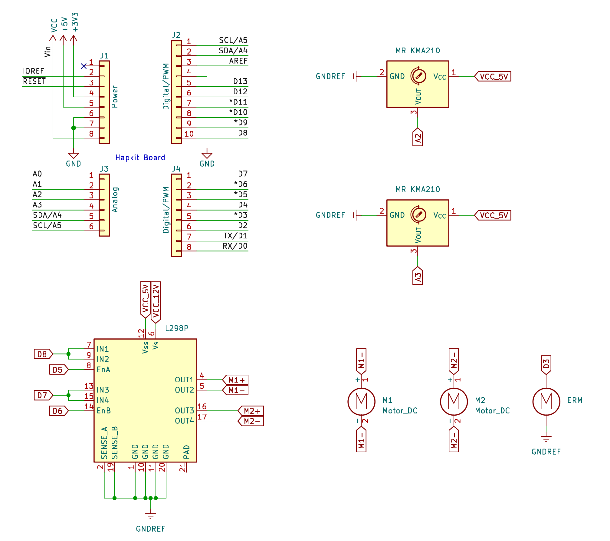
Figure 14: Schematic including all components in final design
After connecting the whole system, we double checked that all components received the proper amount of power by measuring how much voltage each component received. Interfaces that were loosely connected before were soldered together to ensure no leads would be accidentally shaken apart in the midst of transportation or when the users were interacting with the handle. Testing this final system proved effective and allowed us to continue to implement our desired control scheme.
System Dynamic and Control Analysis
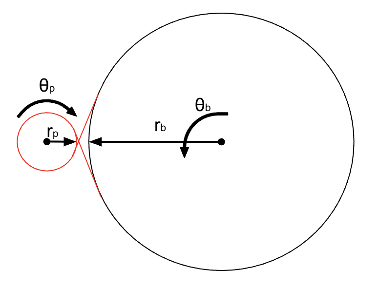
The device consists of two degrees of freedom, one from the rotation of the base that defines the direction in which the user is pointing their swing, the other from the golf handle that the user twists to draw the golf club back and forth to hit the ball. Both subsystems compute position and velocity estimates in real time within the main control loop. An important assumption about the use case allowed a great simplification in the dynamic and kinematic analysis of the device. Given that the user will aim then swing, they will only be actuating one joint at a time, this essentially allow the system to be treated as two separate capstan drive and their kinematics and dynamics are as the following:
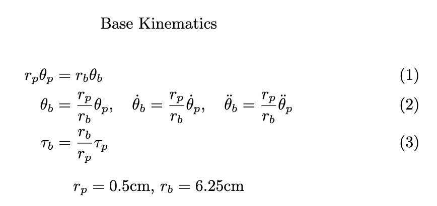
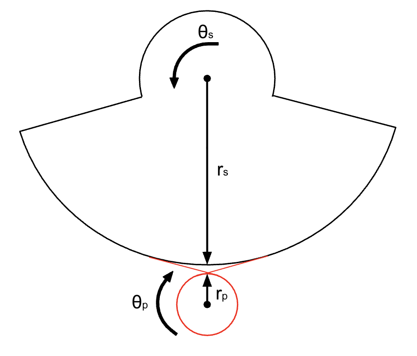
Linear position for each subsystem is determined from measured angular displacement of either the MR sensor of the handle (eq. 4) and the MR sensor of the base (eq. 1), each with dimensions custom to their respective capstan drives.
Velocity was estimated through the differencing of successive position measurements with a time step of 1ms, the approximate sampling interval. To reduce measurement noise and improve control stability, a first-order infinite impulse response (IIR) low-pass filter was applied to the velocity estimate. Filtered velocities were used for both damping calculations and impact-response modulation.
For force feedback, the simulator incorporates two distinct haptic modalities: continuous kinesthetic feedback through motor actuation and localized cutaneous feedback through vibration.
In the base, viscous damping forces are applied so that when the user is interacting with the handle, there is enough resistance within the base that it will not involuntarily rotate without the user intentionally moving it. The calculated force is transformed into motor torque using the pulley transmission relationship (eq. 3) and converted into a PWM duty cycle to be applied to the base motor.
The handle subsystem implemented something similar to a virtual wall to simulate ball impact. When the handle displacement was within a certain range, a restoring force was generated according to a virtual spring model. After impact, no force is generated by the motor and the handle becomes passive. This force is also rendered as a motor torque (eq. 6) and converted to a PWM duty cycle applied to the driver motor.
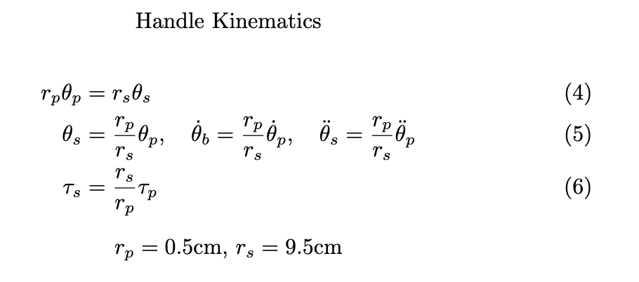
To augment the kinesthetic interaction, an ERM vibration motor was incorporated to provide cutaneous impact feedback. Collision events were detected when the handle position was within a certain boundary (virtual position of the ball). Upon impact, the ERM motor was activated for a short, fixed duration pulse, with vibration intensity scaled proportionally to the magnitude of the filtered handle velocity. This approach allowed stronger collisions within the simulation to produce more pronounced tactile feedback. PWM signals generated by the microcontroller controlled ERM intensity in real time, enabling synchronized tactile responses with simulated golf-ball impacts. The combination of kinesthetic force rendering and vibration-based tactile feedback created a multimodal haptic interaction system that enhanced user immersion and realism during gameplay.
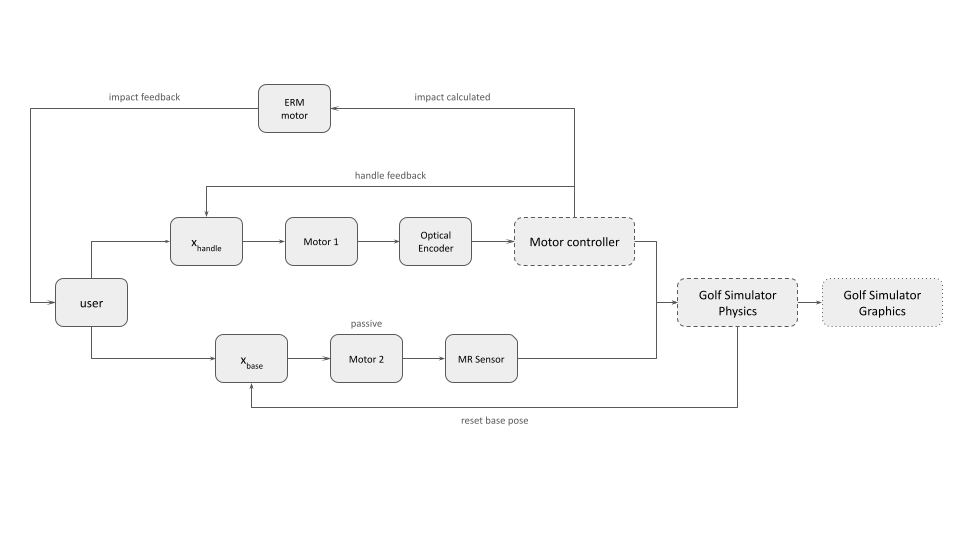
Figure 15: Controls Flow Diagram
Software and Graphical Integration
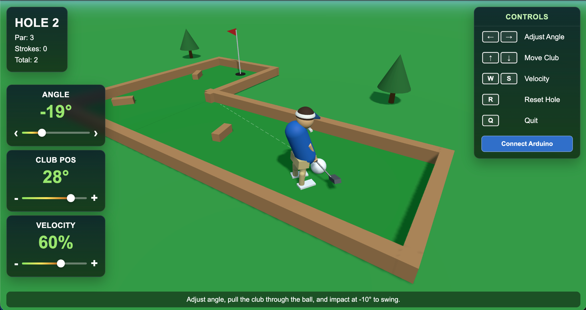
Figure 16: Graphic user interface for 9-hole mini golf course
The graphical interface was integral in giving the user an immersive experience with the haptic device. With approval from course staff, generative AI was used to render a 9-hole mini golf visualization that launched in the local host of the laptop connected to the Arduino board. The game features a golfer avatar with a club, a ball, the greens course with obstacles, a flag pole goal, and text on-screen to guide the user. While the dynamics of the haptic interface were rendered through Arduino, the graphic interface took in the club angle, position, and velocity as inputs through the Arduino serial print out to control the avatar and the golf ball virtual dynamics. The golfer always spawned next to the ball, and when the user changed the base angle of the turn-table, it would change the dotted line trajectory of the ball. When the user swung the club back, the avatar would also swing the club back, and depending on the velocity of the haptic interface club when it strikes the ball, it would control the power of the swing. While prototyping, we used the space key to "fire" the ball, but that is not an input from the haptic device. Thus, we programmed the system such that if the club was at -25 degrees it would assume contact with the ball, which allowed the user to aim while avoiding false contacting the ball. The user must restore the club to nominal position before the next shot was set up to prevent hitting the ball (which we thought was realistic to inadvertent swings in real golf!)
Between the golf ball and the grass there is some friction simulated to prevent the ball from rolling forever (so the user can set up the next shot). Near the flag pole, there is also a small region where the ball would get "sucked" into the goal such that the game doesn't last forever (like real putting can take). These features allowed for a more enjoyable gaming experience. Finishing one hole would take you to the next hole, until all 9 were complete and game finished. Each hole was a randomly generated L-shaped course with some wooden block obstacles. There were additional reset buttons in case the ball got stuck or if the user wanted to start again.
Demonstration / Application
To see a demo video of our project please download the link above! For our live demonstration we set up the haptic device with a laptop to display the graphical interface for the golf game. The haptic device is being powered by the wall outlet of the power supply, and the Arduino board is connected to the laptop. On the computer, there are two code applications running. The Arduino IDE is reading back the base angle, club position, and club velocity live. Arduino code is also rendering the virtual wall and vibration motor when the club contacts the ball. The Arduino code also streams the angle and velocity variables and the second code application in python is reading it in. The python code renders the graphical interface in the local host and visualizes the user's actions with the golfer avatar.
Each user is set up with a new game of 9-hole golf. The first hole is the simplest hole so the user can get used to the interface. it is a simple straight shot to the goal. The user is instructed to use the base swivel to control the trajectory of the ball and the handle to swing the club back and forth. This first hole gets the user used to the coefficient of friction between the virtual golf ball and the grass, as well as how far they need to swing the club before contact happens. The hole is designed to take more than one shot in order to train the user on how to reset the handle between shots as well.
Once the user finishes the first hole, they can press a button on the laptop to go to the next hole. The subsequent holes get more challenging with longer courses and more obstacles between the starting position and the flag pole. The user is able to reset the hole at any point if they want. Once all 9 holes are complete, there is a celebratory finish screen where the user can see how many shots it took them to finish the game and how well they scored. Upon pressing the reset button the game and haptic device are ready for the next user. Each user is also asked to complete a survey after trying the haptic device.
Results
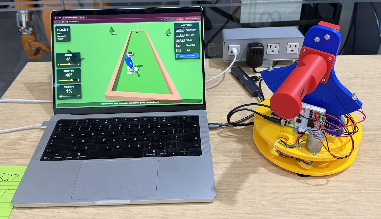
Figure 17: Mini golf haptic at haptic open house
User Feedback
During the haptics open house, many people came and tried the mini-golf haptic simulator. Many who tried enjoyed the augmentation of a familiar game and were drawn in by the visual graphics and gameplay. Emphasizing the lightheartedness of the project, we hoped to extend some of the fun and excitedness to those who were playing mini-golf.
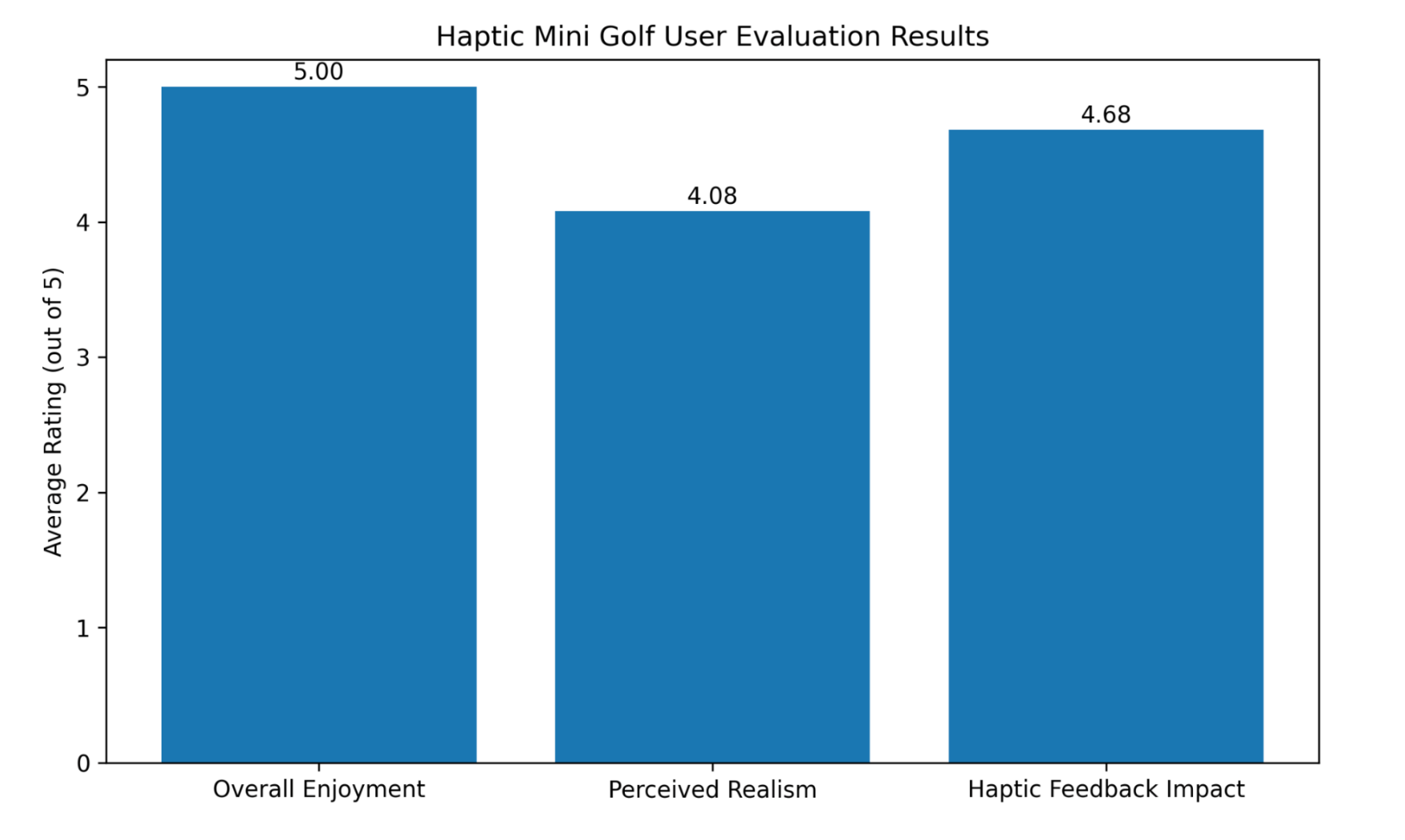
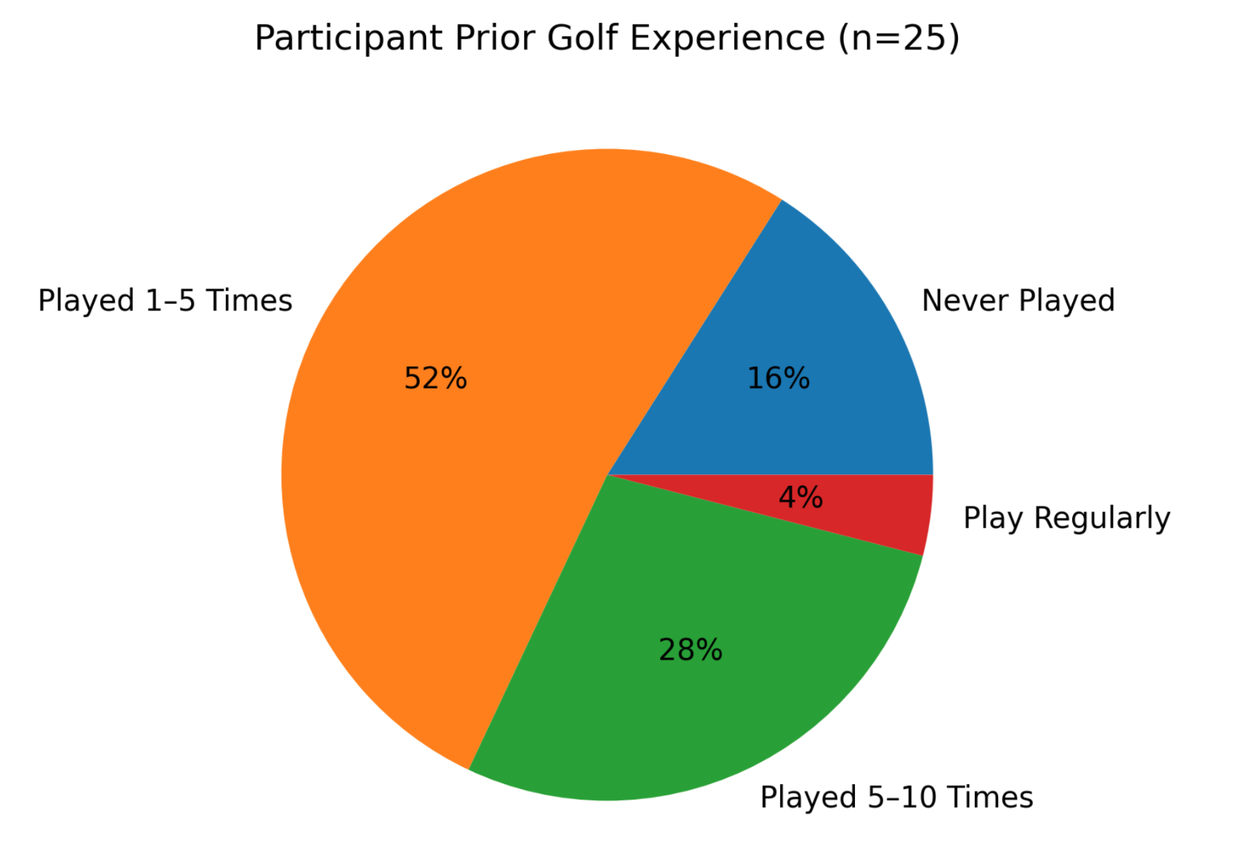
To evaluate the effectiveness of the Haptic Mini Golf system, a user study was conducted during the final project demonstration with 25 participants. The survey assessed overall enjoyment, prior mini golf experience, perceived realism, the impact of haptic feedback, and willingness to play the game again. Participants were also invited to provide open-ended feedback regarding their favorite aspects of the system and potential improvements.
The survey results indicate a highly positive reception of the Haptic Mini Golf system. All 25 participants (100%) rated their overall enjoyment as 5 out of 5. Participants had varying levels of mini golf experience, ranging from first-time players (16%) to regular players (4%), suggesting that the game was accessible and enjoyable across different experience levels.
The game was also perceived as a realistic representation of mini golf, receiving an average realism rating of 4.08 out of 5, with 88% of participants selecting a rating of 4 or 5. Haptic feedback was identified as a key contributor to the experience, earning an average rating of 4.68 out of 5, with 76% of participants assigning the maximum score. These results demonstrate that the combination of haptic interaction, virtual gameplay, and visual feedback successfully enhanced user immersion. In addition, all participants indicated that they would be willing to play the game again, reflecting strong replayability and overall satisfaction.
Open-ended feedback further reinforced these findings. Participants frequently highlighted the impact sensation, ERM vibration feedback, graphics, user interface, and variety of courses as their favorite aspects of the game. Several users also praised the smooth and intuitive interaction provided by the two-degree-of-freedom haptic device. Overall, the feedback suggests that the successful integration of haptic rendering, mechanical design, and graphical presentation was a major factor in creating an engaging user experience.
Participants also provided valuable suggestions for future improvements. Mechanical recommendations included improving the reliability of the cable transmission system, refining rotational limits, and implementing logic to prevent repeated unintended hits. Several users expressed interest in stronger or more dynamic haptic effects, such as force feedback that scales with swing strength and increased damping during the swing motion. Additional suggestions focused on improving the mapping between physical and virtual motion, including more intuitive directional control and enhanced avatar movement. Participants also recommended visual improvements such as clearer aiming indicators, improved trajectory visualization, and preventing the ball from being obscured by the player character.
Overall, the survey results demonstrate that the Haptic Mini Golf system successfully achieved its primary design goals of creating an engaging, intuitive, and immersive haptic gaming experience. Future work will focus on enhancing both the physical and virtual interactions through improved cable-drive mechanisms, adaptive haptic rendering, dynamic force effects based on swing characteristics, enhanced visual feedback, and more advanced golf physics.
Future Work
The current Haptic Mini Golf system establishes a functional platform for exploring haptic interaction in virtual sports applications. Future work may include additional experimental evaluation, improvements to the mechanical and electrical design, and the development of new features that enhance realism, immersion, and usability. User feedback collected during the final demonstration also identified several opportunities for improvement, including stronger and more dynamic haptic effects, improved visual feedback, enhanced control mapping, and greater gameplay variety. These observations, combined with the team's own design insights, provide several promising directions for future development, as discussed below.
- Optical Encoder Position Sensing
Due to time constraints and hardware integration challenges, the final prototype utilized MR sensors for position sensing. Future work could revisit the implementation of dual optical encoders, allowing both degrees of freedom to be measured with high angular resolution. A fully functional dual-encoder system could improve position accuracy, reduce sensor noise, and provide more precise motion tracking for advanced haptic rendering and gameplay experience.
- Wireless Connectivity and Mobile Integration
The current system relies on a wired connection between the haptic device and the computer running the game. Future versions could incorporate Bluetooth or other wireless communication technologies to improve portability and user convenience. Wireless connectivity would also enable integration with mobile devices, tablets, or standalone embedded systems, allowing the game to be deployed in a wider range of environments without requiring a dedicated computer connection.
- Multi-Sensory Gaming Experience
While the current prototype primarily relies on visual and haptic feedback, future iterations could evolve into a more immersive multi-sensory gaming platform. Additional sensory cues, such as audio effects, environmental lighting, and richer vibration patterns, could be synchronized with gameplay events. For example, different impact sounds, crowd reactions, or environmental effects could be combined with haptic feedback to create a more realistic and engaging virtual mini golf experience.
- Interchangeable Golf Club Attachments
The current design uses a single golf club attachment for all gameplay interactions. Future versions could introduce interchangeable club attachments that emulate different golf clubs, such as putters, irons, and drivers. Each club could be associated with unique virtual ball physics, including variations in launch angle, travel distance, spin, and impact behavior. This feature would introduce additional strategy and realism while expanding the educational and training potential of the platform.
Acknowledgments
We wanted to acknowledge the help and support we received from Allison and the teaching staff for their expertise and guidance throughout the project process. We utilized resources from the Charm Lab which were crucial in our design process and functioning of our device. Thank you for an enriching quarter.
Files
Game UI: Attach:HapticGolf_9Holes.py Δ
Github repository: https://github.com/anbananna/me327_haptic_golf
References
[1] C. Basdogan and M. A. Srinivasan, �Haptic Rendering in Virtual Environments,� 2001. [Online]. Available: https://www.researchgate.net/publication/2380464_Haptic_Rendering_in_Virtual_Environments
[2] T. Nakamura and H. Koike, �Golf Club-Type Device with Force Feedback for Modifying Club Posture,� in CHI EA �20: Extended Abstracts of the 2020 CHI Conference on Human Factors in Computing Systems, New York, NY, USA: ACM, 2020. doi: 10.1145/3334480.3383024.
[3] A. Tekriwal and S. Sharma, �GolfGuide: Smart Golf System with Haptic Feedback and Auditory Cues for Visually Impaired Individuals,� in 2025 7th International Conference on Intelligent Sustainable Systems (ICISS), India, 2025, pp. 907�916. doi: 10.1109/ICISS63372.2025.11076425.
Appendix: Project Checkpoints
Checkpoint 1
- Goal:
By this checkpoint, we aim to have the mechanical prototype about 80% completed through 3D printing, with the motor and required sensors selected. The design requirements and specifications should be finalized, including defining the intended gameplay objectives and the user experience we want to create (e.g., target sensations and interactions). The mechanical and electrical systems should be integrated and ready for initial code testing. On the software side, the game should have a functional basic version completed, including core game logic and essential in-game objects.
- Team Progress Update:
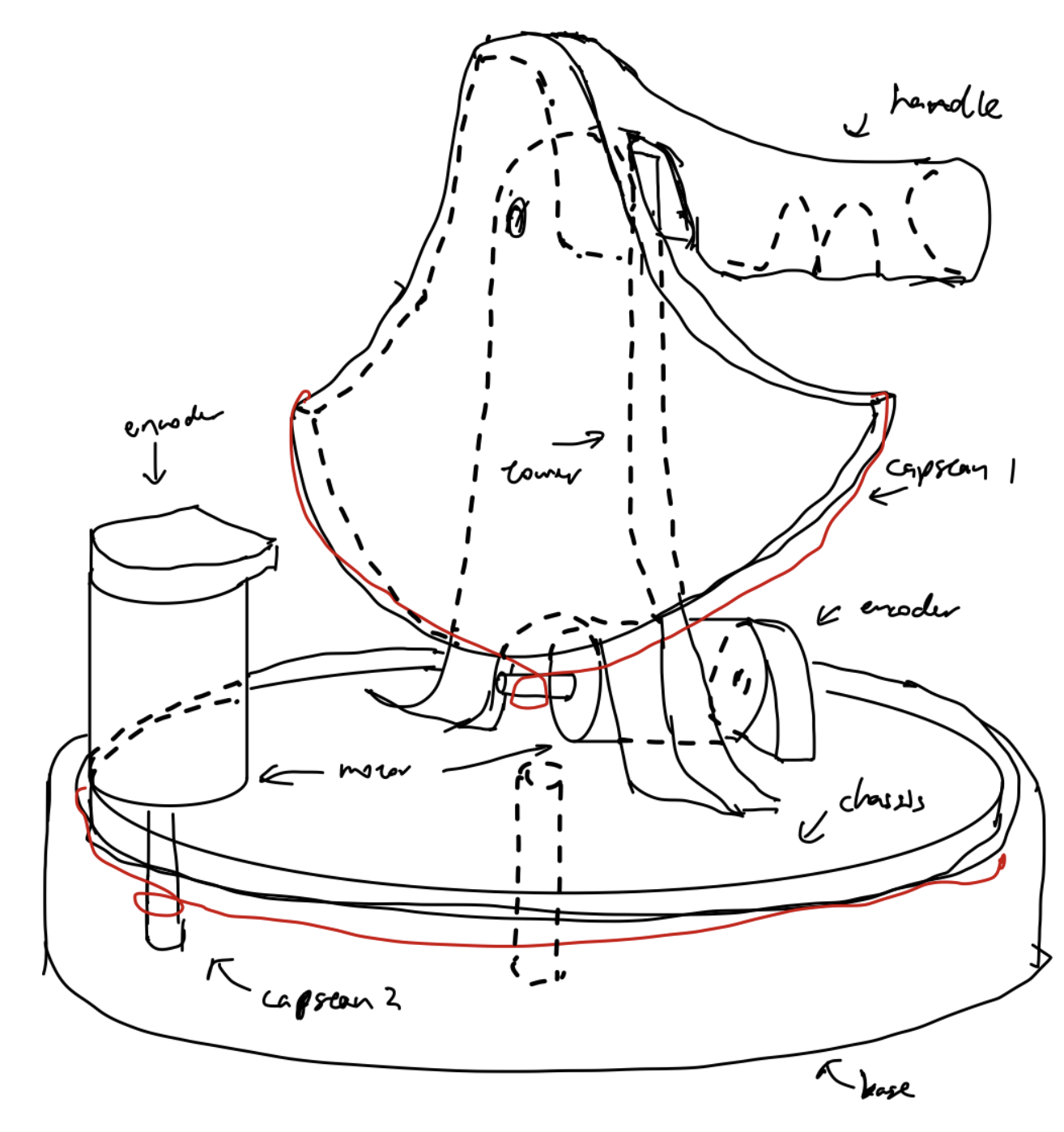
Figure A1: Initial concept drawing
At this checkpoint, the project has made solid progress toward the planned goals, although several integration tasks are still in progress.
From the mechanical perspective, the device design is approximately 80% completed in CAD. The overall assembly architecture has been defined, including the three major mechanical subsystems:
- Base + chassis + Motor 1 + Capstan Drive 1
- Tower assembly + Motor 2 + Capstan Drive 2
- User handle + golf club + vibration motors + linkage mechanism
Currently, the base section of the device has been 3D printed and used for initial fit and structural evaluation. However, the complete mechanical assembly has not yet been fully fabricated or assembled through 3D printing.
On the hardware side, all major actuation and sensing components have been selected, including the DC motors, optical encoders, and vibration motors. The team has also continued refining the mechanical linkage and interaction design to support the intended golfing motion and haptic feedback experience.
From the software perspective, a basic graphics environment has been generated, and the initial code structure and signal mapping framework have been developed. These include preliminary templates for integrating device motion and gameplay interaction. However, the software modules and mappings have not yet undergone full team review or integrated testing.
Overall, the project has established the core mechanical architecture, selected the required hardware components, and initiated both software and system integration development. The next phase will focus on completing full mechanical fabrication and assembly, integrating the electrical and mechanical systems, validating sensor and motor functionality, and refining the gameplay and haptic interaction experience through testing and iteration.
https://docs.google.com/spreadsheets/d/1z032SW_FavX9c2kPuF-KOvd41SU4SF96tfZlnoqKBLc/edit?usp=sharing
Base + Chassis:
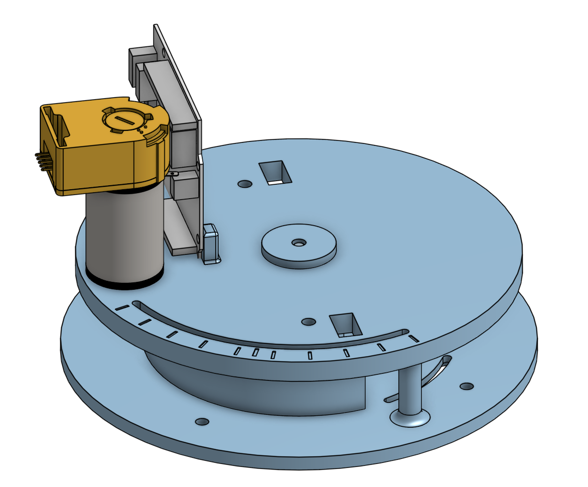
Figure A2: Base and chassis CAD along with the Hapkit board, motor, and encoder
Attach: Printed BaseChassis.png Figure A3: First iteration of the base and chassis printed and assembled
Tower + Sector Wheel:
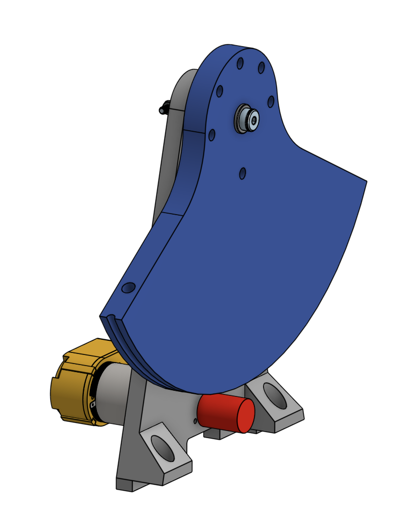
Figure A4: Initial CAD design of tower subassembly that houses 2nd capstan drive
Linkage mechanism:
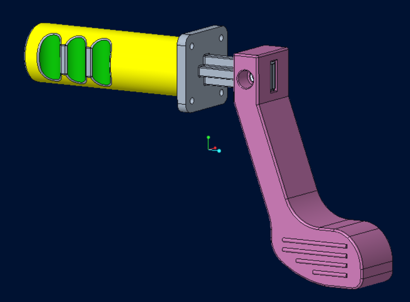
Figure A5: Initial CAD design of handle with mock golf club
Checkpoint 2
By checkpoint 2, our team has a completed working prototype of the mechanical device while working in parallel on an electronics circuit buck and coding up the first version of the device kinematics and graphical interface.
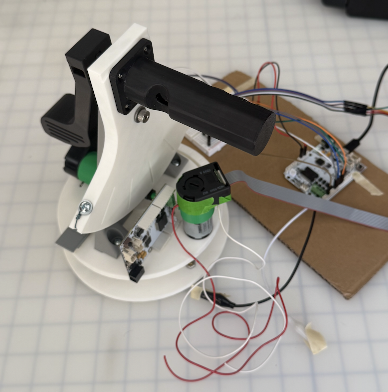
Figure A6: First prototype
For the mechanical portion, we have a swivel rotating base with the capstan drive motor mounted to the rotating chassis. The chassis also houses the Hapkit board next to the motor. We also have a tower that uses dovetail joints and heated inserts to mount to the chassis. The modular design allowed us to iterate on these two actuated components separately without excessive print times. The golf handle is designed to bolt into the top of the sector drive and then slot into a swappable mini golf club. We went through several iterations of each part to tune the fit of the 3D printed holes for the bearings, screws, heat set inserts, and slotted press fits. We also have to add adhesive counterweights on the swivel to balance out the mass of the tower for the chassis to rotate more evenly.
With the electronics portion we encountered the most challenges. Specifically, the optical encoder sourced for the project is having issues with light leakage and inconsistent readings unless we put the device in a dark room. At first we thought it was an issue with the pull-up resistors or the coupling between the encoder and the motor, but upon covering up the encoder with our hands we found that it was sensitive to the overhead lighting in the room. As a result, we plan to use the dust cover of the device to seal the device from excess light. We were able to wire all the necessary components to 1 Hapkit board and a breadboard (2 encoders, 2 motors, 1 ERM motor), allocating proper PWM and DIR pins for each motor. We were also able to drive each motor separately with the power supply while connected to the same Hapkit board.
To facilitate the torque control, the kinematics of the devices developed. One important assumption we make to simplify the kinematics, is that the two joints will move completely independently. This assumption arise from the fact that we want the user to use the first joint to aim, then the second joint to hit the ball, at no point should the user use both of the joints. With this assumption, the golf haptic device is simplified to two capstan drives, with each of their Jacobians as ratios of their respective radii.
Joint 1:
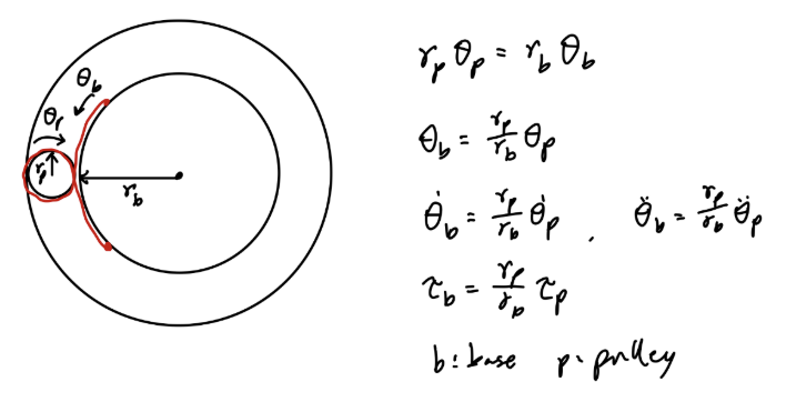
Figure A7: Joint 1 diagram; here, the radius of the pulley: rp = 0.7cm and the radius of the base: rb = 5.2cm
Joint 2:
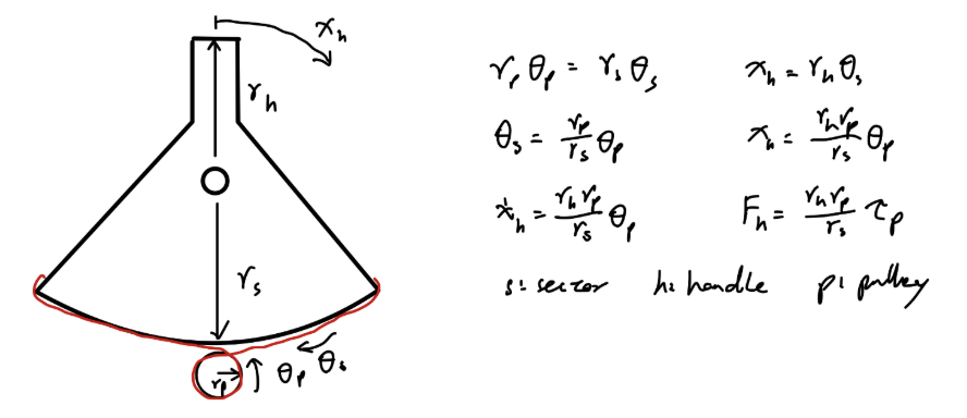
Figure A8: Joint 2 diagram; here, the radius of the sector pulley: rs = 9.5cm and the radius of the handle: rh = 3.8cm
For the graphics coding portion, we have a mini-game of golf with 9 holes. While prototyping, we use the keyboard input as the swing power and angle, but it will be replaced with the Arduino code that streams the encoder positions. The golf ball dynamics includes friction against the grass so it does not roll forever, and there is a feature for the golf ball to funnel into the golf hole when it is close enough to prevent the game from taking too long to complete. The trajectory of the golf ball is shown with a dotted line that moves with the swing angle and gets longer or shorted based on the swing power. When we replace the keyboard with the haptic device we will directly control the swing angle and power.
One piece of feedback from testing with a user is that our handle ergonomics does not feel perfectly natural. Due to the handle offset we added to the fit the golf club, the user has to kind of twist their wrist to actuate the swing DOF. As a result, we decided to shift our handle mounting to resemble more of a "foosball" handle to improve the user experience.
Our next steps are to drive both motors simultaneously and simulate a virtual wall with the swing DOF. Then we will use the encoder reading of the swing and angle DOF to control the graphic interface. The major unknown is whether both actuators can be driven only with the single power supply and Hapkit board. Afterwards we will integrate the vibration motor to the handle and clean up the wiring to be more invisible. We also need to make changes to the handle as mentioned above and design light blockers for the encoders to increase reliability.