2026-Group 17

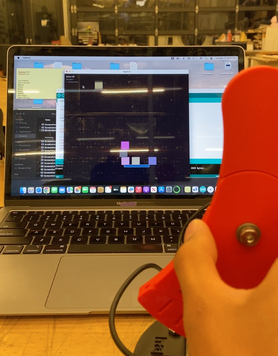
Stack'em in action
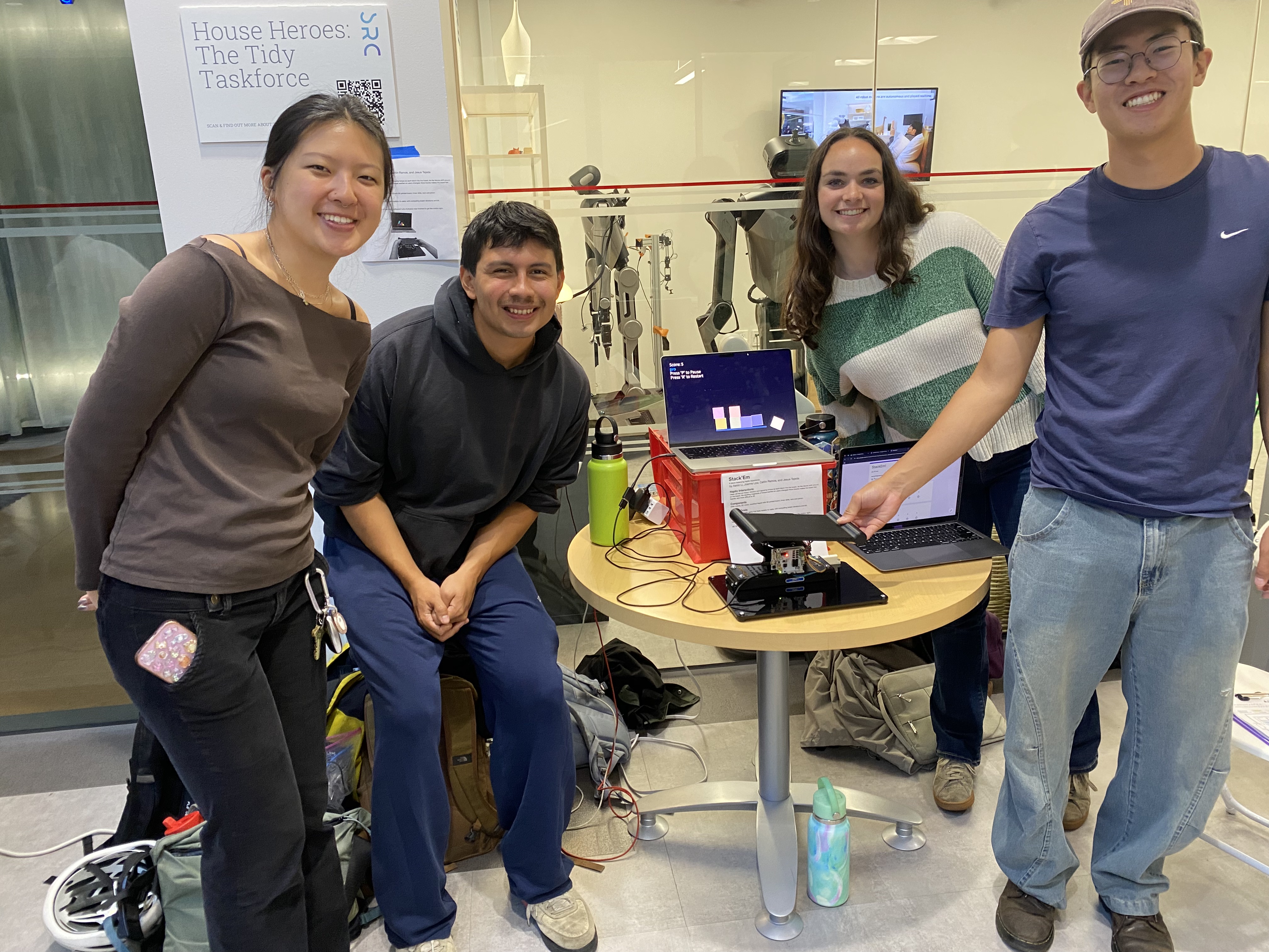
Group 17 Team Members
Stack'em
Project team members: Aaron Li, Caitlin Ramos, Jesus Tejeda, Joanne Low
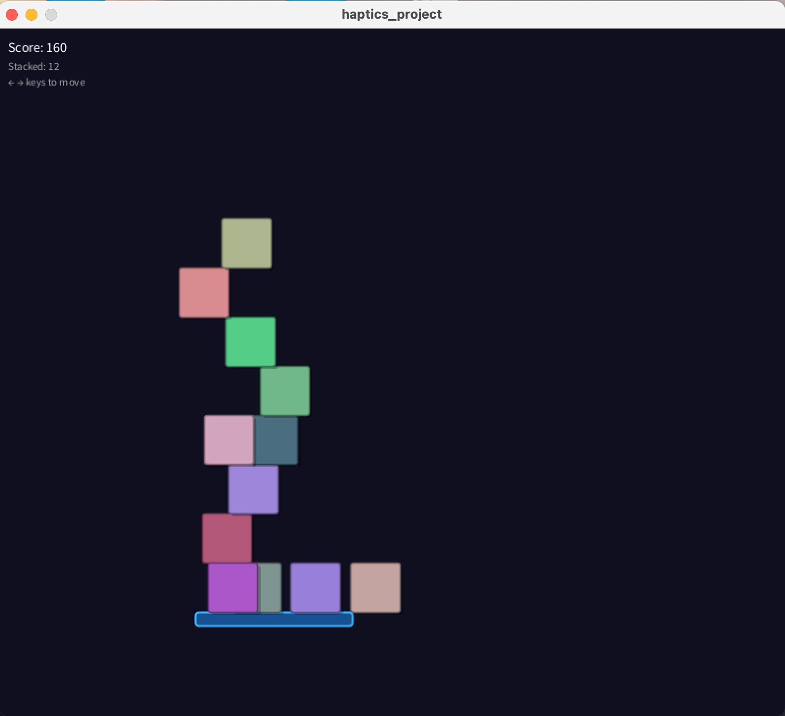
For our project, our group designed an interactive game that allows users to move a physical platform in order to catch and balance a stack of falling blocks in a virtual environment. The main motivation of this project was to enhance the immersion experience of traditional video games by implementing haptic feedback to produce realistic sensations of the blocks' impact, movement, and weight as the user interacts with the physical platform. There is a DC motor that provides force feedback via an applied torque as well as ERM motors that vibrate when a block lands on the platform to simulate impact. The applied torque varies with block impact, block stack positioning, and number of blocks on the platform to realistically mimic the forces that would be felt if actual blocks were landing on the platform. During the final showcase, the project received positive feedback from participants, who reported that the platform felt realistic and that the force-feedback effects were immersive and compelling.
On this page... (hide)
Introduction
This project explores human-computer interaction by integrating haptic feedback into a block balancing video game. Our main motivation was to successfully create a system that provides accurate feedback as the user responds to various stimuli such as changes in inertia, impact forces, and gravitational effects. By giving users real-time force feedback as the blocks move on the platform, the device reinforces the relationship between physical input and environmental response. Through the design and testing of this project, learning goals centered around dynamics modeling, physical design, and haptics rendering were achieved. The choice of haptic device for this project is appropriate for these learning objectives because the implementation of the DC and ERM motors enabled us to design the appropriate force feedback to physically simulate the effects felt in the virtual environment.
Background
In current related haptic devices, capstan drives are often utilized due to their high torque transparency, zero backlash, high stiffness perception, and minimal friction. These qualities allow for haptic devices to provide smooth and accurate force feedback to the user. There are many advancements in the design and engineering of capstan drives themselves to improve their responsiveness, torque transparency, size, and other factors. Some examples in recent research include the usage of electro-adhesive clutches to increase back-drivability and force output [1] and usage of synthetic materials for cable design to decrease system weight while maintaining a compact form factor [2]. Our project utilizes a capstan drive due to its high torque output and precision.
Another important topic in haptics research for this project is the exploration of weight perception. Methods such as damping manipulation and pseudohaptics are ways to make the perceived weight and forces of a haptic device more realistic. When the damping increases in a system it can often create the illusion that the object is stiffer and more difficult to move [3]. This technique is very commonly used in many different haptics applications such as medical training devices, spatial rendering tools, and VR simulations to enhance the perceived stiffness and weight of a virtual object. Another approach to amplify weight perception is pseudo-haptics, which focuses on manipulating visual and auditory cues to trick the brain into feeling certain tactile sensations. A notable example of pseudo-haptics for weight perception is the manipulation of control-to-display (C/D) ratio. This method utilizes the concept that lighter objects are easier to move to create an illusion of weight by making the rendering of the user�s position larger or smaller based on how �light� or �heavy� the object is [4]. Another example of visual manipulation to make virtual objects feel heavier is visual delays, where �heavier� objects have a delay in movement relative to the input from the physical world [5]. These examples illustrate the various methods in which perceived weight and forces can be refined to improve the feedback experience for all kinds of haptic applications.
Methods
The haptic gameplay in Stack�Em relies on three core components: physics simulation, haptic rendering, and a hardware interface (illustrated in the figure below). Processing software in Java serves as the primary engine, computing both the physics simulation and the haptic rendering parameters which are sent to the hardware interface. The hardware interface is made up of the Hapkit board, an Arduino UNO based microcontroller, and the physical interface held by users. The haptic parameters are first sent to the Hapkit board which interprets the data and drives two ERM and DC motors respectively applying vibrations and torque to the user. The user�s inputs are similarly relayed from the physical interface via the Hapkit board to the physical simulation to update the platform position and angle.
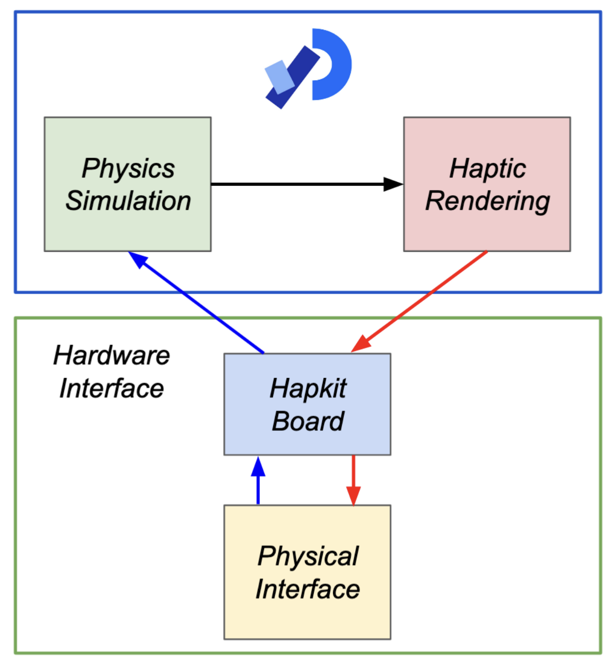
Stack'Em System Design
Physics Simulation
To achieve realistic and reactive rigid-body dynamics for the blocks within Stack�Em, we utilized Box2D, a 2D physics engine that handles all collision and movement calculations. In order to create a game environment which both matched physical intuition but also lent itself to a fun gameplay experience we tuned various parameters within our virtual world. The first of which was the scale of the universe being rendered. Box2D functions in SI units meaning pixels must have a conversion factor to meters. This value itself is not critical and must only take into consideration that Box2D functions best with objects between 0.1m and 10m. From testing, we settled on a value of 189 pixels per meter, resulting in blocks ~0.6m in size and a platform of ~3.0m. Gravity was set to our accustomed 9.8m/s2 to give a realistic reference during tuning of the remaining parameters.
In the virtual world of Stack�Em there are two types of objects, the falling blocks and the platform. Block objects are each identical in size and physical characteristics. They have a set width, height, density, friction, restitution, and damping. The table below indicates the value these parameters were tuned to and accompanying notes on how Box2D implements them.
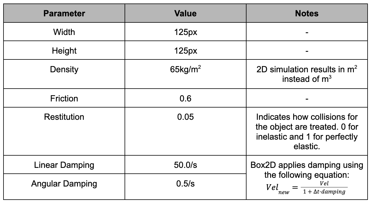
Block Parameter Values
The platform is handled slightly differently. Because it is user controlled, it is treated as a kinematic boundary object, meaning that it does not react to gravity, collision, or laws of motion but does have its own velocity, friction, and restitution values which are outlined below.
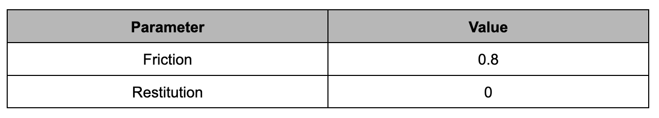
Platform Parameter Values
The platform's velocity (angular and linear) are derived from user inputs. We use a proportional controller to obtain velocities while Box2D handles the integration to position. The gains were found experimentally for linear velocity and made equal to the 1/timeStep for the angular position.
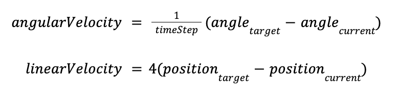
Velocity & Angle Control Equations
The high angular velocity gains result in an instantaneous matching of the virtual and real angle of the platform within a timestep. This was selected so as to not interfere with the haptic feedback, potentially causing discrepancies between the rendered state of the game and the platform position.
Haptic Rendering
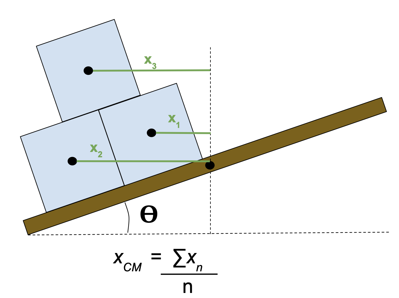
Our haptic rendering is made of four fundamental elements: base duty cycle, impact gain, angular damping, and ERM duty cycle. Each of these components are updated every timestep based on the rendered simulation. The base duty cycle is responsible for creating the sensation of weight from the stack of blocks on the platform. Via a helper function running each timestep, the number of blocks currently sitting on the platform are counted and their center of mass (CoM) found with respect to the platform center.
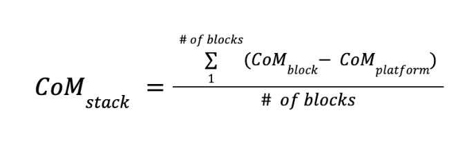
Block Stack Center of Mass Calculation
Based on CoM_stack, we calculate a torque using the number of blocks on the platform, mapping the result to the range of 20-255 so it can be interpreted by the Hapkit board. We purposely begin the mapping at 20 so that even at distances close to the platform center, a noticeable torque is felt by the user. Because the duty cycle cannot encode direction, we identify which side of the platform the CoM_stack lies on and stores this as a separate piece of information. A value of 1 indicates CoM_stack lies on the left side and 0 for the right side.
The impact gain is a value which is calculated when a �large� impact is detected. We developed a class which intercepts and analyzes all rendered collisions allowing us to categorize and compare collision events. A �large� collision is labeled as one where the collision force exceeds a predetermined threshold, in our case 60N. The threshold was tuned experimentally to cause the impact gain to trigger only when a new block would hit the platform and ignore the smaller block-block collisions due to platform movement. The amount of gain is determined by the following:

Impact Gain Calculation
The addition of the constant is to scale the simulated force to fit within the 0-255 scale of duty cycle. The impact gain is then added on to the base duty cycle. Rather than immediately removing it in the next frame, we exponentially decay the gain over the following timesteps so that the impact is blended.
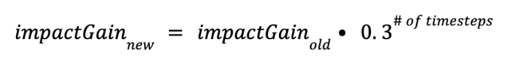
Impact Gain Decay
The last modifier to the base duty cycle is via angular damping. As blocks accumulate on the platform it should become heavier and thus harder to move due to added inertia. We represent this using damping. The following equation determines the amount of damping provided.
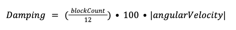
Damping Calculation
The leading terms are once again used to scale the value so that they fit in the duty cycle range. As a result, the total duty cycle fed to the DC motor is a summation of base duty cycle, impact gain, and damping.
The last element are the ERM motors providing vibratory feedback. These are triggered in a similar fashion to the impact gain. When a collision force is detected which has exceeded 25N the ERM motors are triggered with a corresponding duty Cycle which is mapped between the values of 110 - 255 to ensure the motor inertia is overcome. The value of 25N was tuned so that it was sensitive enough to pick up small collisions from blocks sliding and tumbling on the platform, but ignore micro-collisions caused from blocks in close proximity. Each timestep, we map the ERM duty cycle to the maximum detected collision. With this method, if a large collision is detected and triggers the impact gain, the associated ERM duty cycle is large and not based on a smaller collision which also may have occurred.
All the haptic information is combined during each timestep and a serial package is sent to the Hapkit board with the following structure:
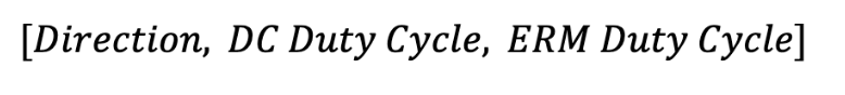
Serial Package Data Structure
Microcontroller Software
The Hapkit board software was developed within Arduino IDE in C++ in order to interface between the real-life electromechanical components and the virtual Processing environment. The board outputs include control of the DC rotation motor and the two ERM vibration motors, while the board inputs include the linear motor encoder values.
Through serial communication, the Hapkit board receives data from the Processing environment in the form of 3 integer values delimited by a �,�. The first value is the direction to actuate the rotational DC motor, while the second value is the duty cycle to actuate the motor at, programmed using the PWM analog write functions within the Arduino IDE. The last value is the duty cycle to program the ERM vibration motors at.
The Hapkit board also sends data into the Processing environment. Using the �Encoder� library by Paul Stoffregen within Arduino IDE, the encoder channel inputs are automatically read and converted into a linear position value that ranges from 0 to 60, end to end on the linear rail. This value is sent to the Processing environment, which is then converted into its equivalent pixel value to display the virtual platform.
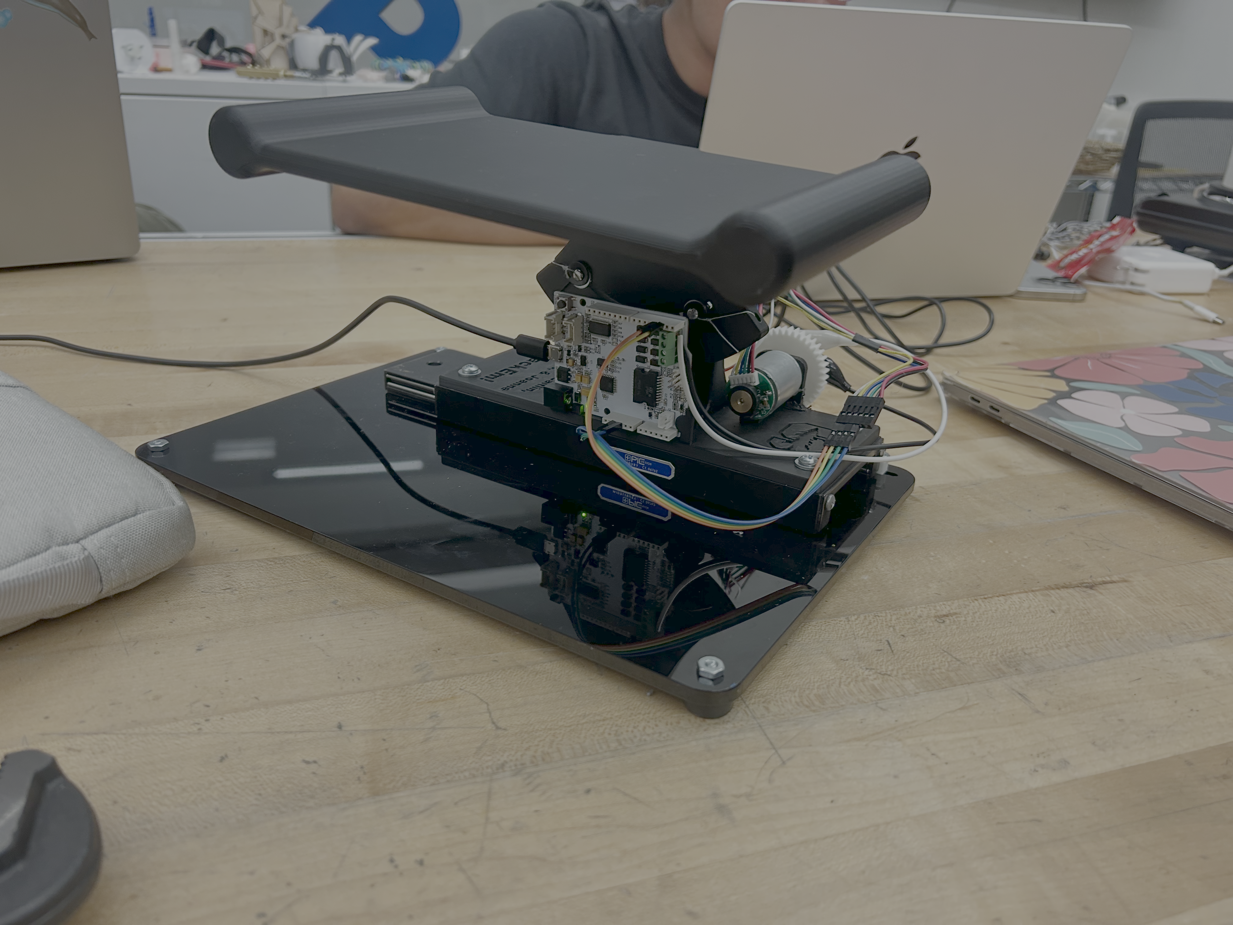
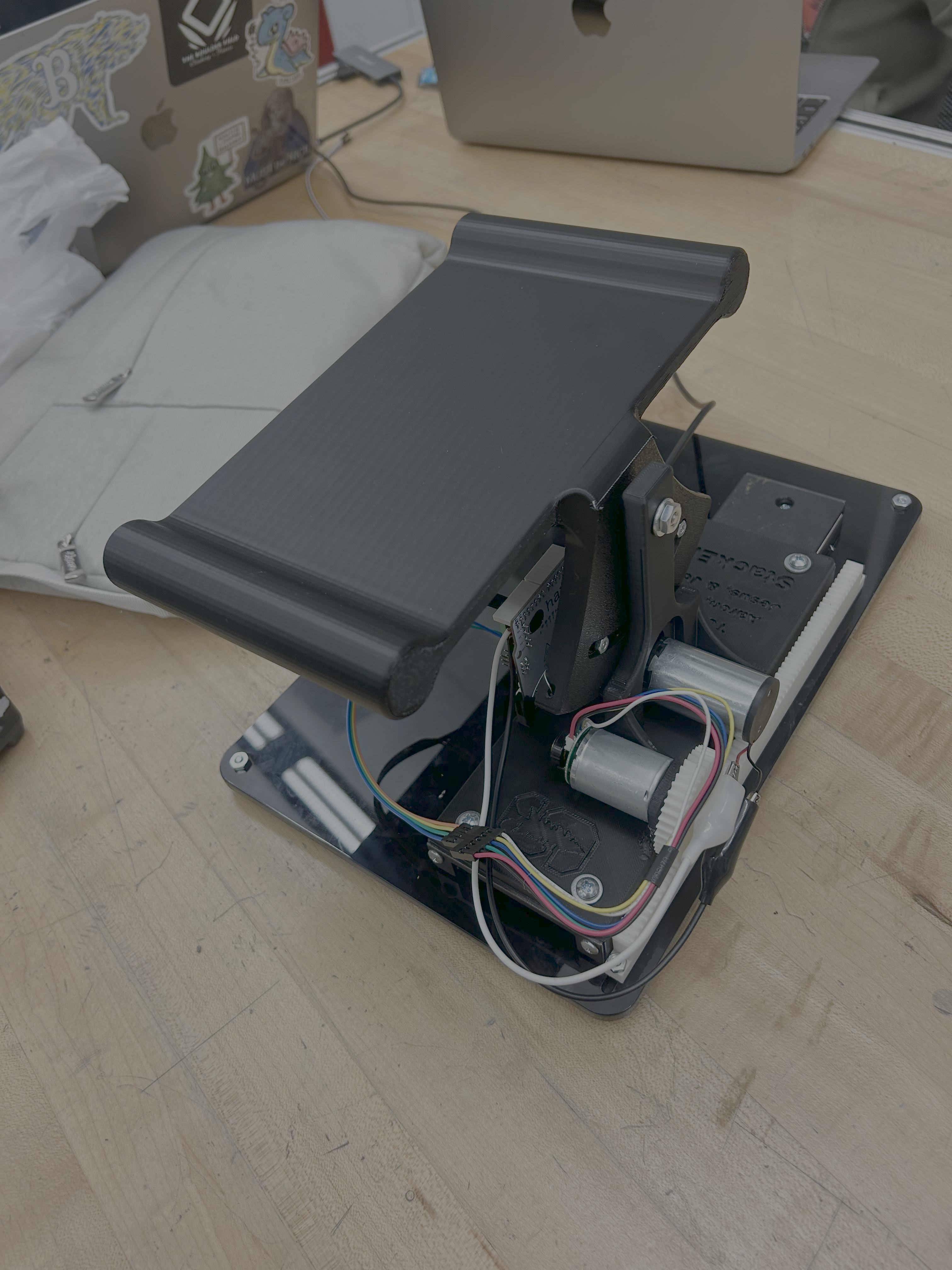
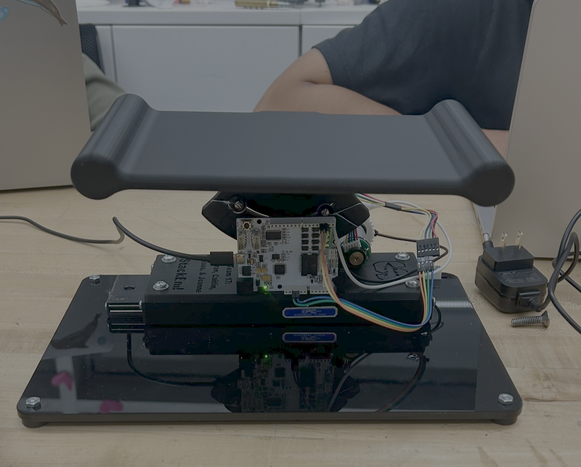
Hardware Design and Implementation
The hardware builds off of a modified Hapkit to achieve the rotation of the board. The board is 3D printed as a single piece attached to the Hapkit pulley sector, allowing it to rotate around the center of rotation of the pulley sector. This is connected to the Hapkit base, which was modified to integrate cleanly with the linear rail underneath it.
The linear rail enables low-friction, smooth linear translation of the entire Hapkit-board system so that the user can slide the system back and forth to catch blocks falling in different locations. The linear position of the board is tracked using a rack and pinion system, which rotates a DC motor mounted to the Hapkit base as the base slides back and forth. As the motor rotates, an encoder deciphers the rotation, and the software converts this into the measured linear displacement of the board. This motor is not actuated and solely used for position tracking. The encoder is powered by the Hapkit board, and the channels A and B of the encoder are connected to pins D2 and D3, respectively.
The rotation of the board is measured using a magnetoresistive sensor attached to the circuit board, which reads the magnetic field from a magnet mounted to the end of a second DC motor, which provides force feedback to the user. As the board rotates, the motor shaft rotates by means of a capstan system, and the rotation of the magnet is captured by the sensor and recorded as the measured rotational displacement of the board. This motor is connected to the motor terminals (M1+, M1-) of the Hapkit board.
There are also two ERM motors attached to the underside of the board handles. These motors are wired in parallel with each other to the same motor terminal (M2+, M2-) on the Hapkit board to vibrate at the same time when triggered. These motors are triggered to vibrate when a block lands on the stack in the virtual environment to simulate the impact forces.
The entire system is mounted to an acrylic base plate to secure the components. The base plate has silicon feet attached to the bottom to prevent the plate from sliding around on the table as the user plays the game.
The circuit board must be connected to a power source and a computer with Arduino IDE and Processing software installed in order for the game to run. The Hapkit board is programmed with Arduino IDE and powered by a 12V barrel jack power adapter. Serial communication occurs by connecting the board to the computer using a micro USB to USB-A cable.
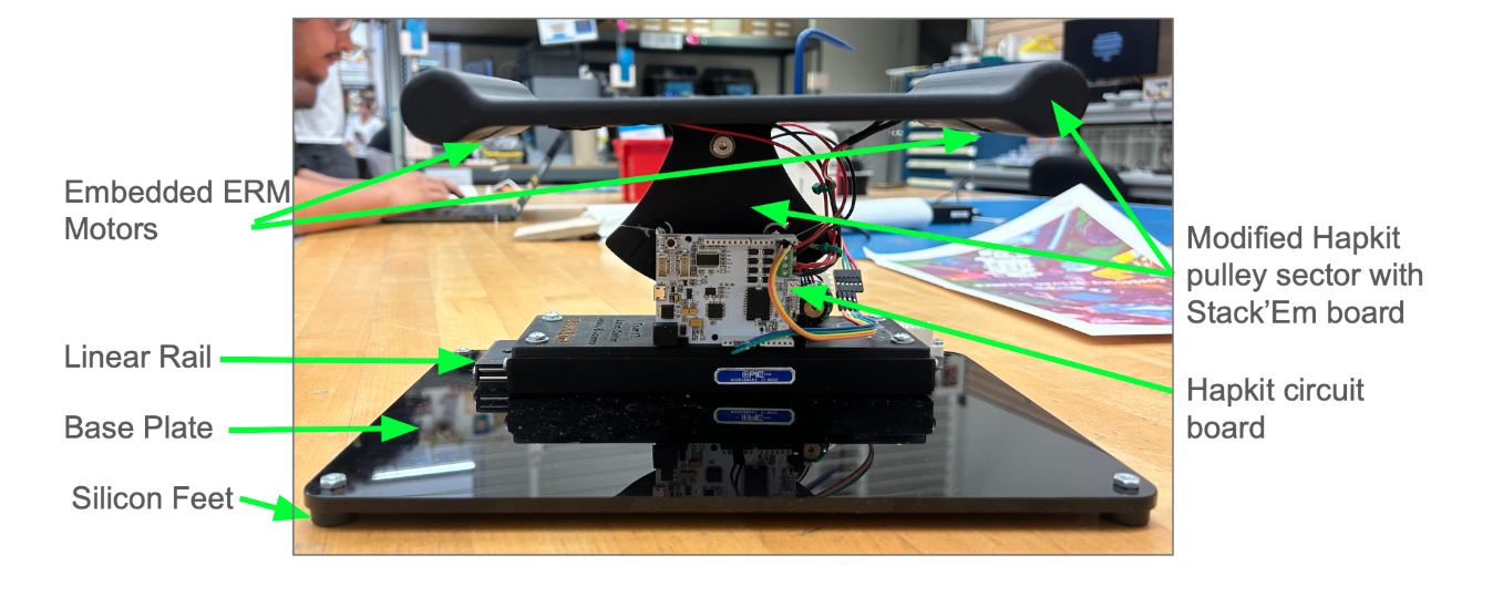
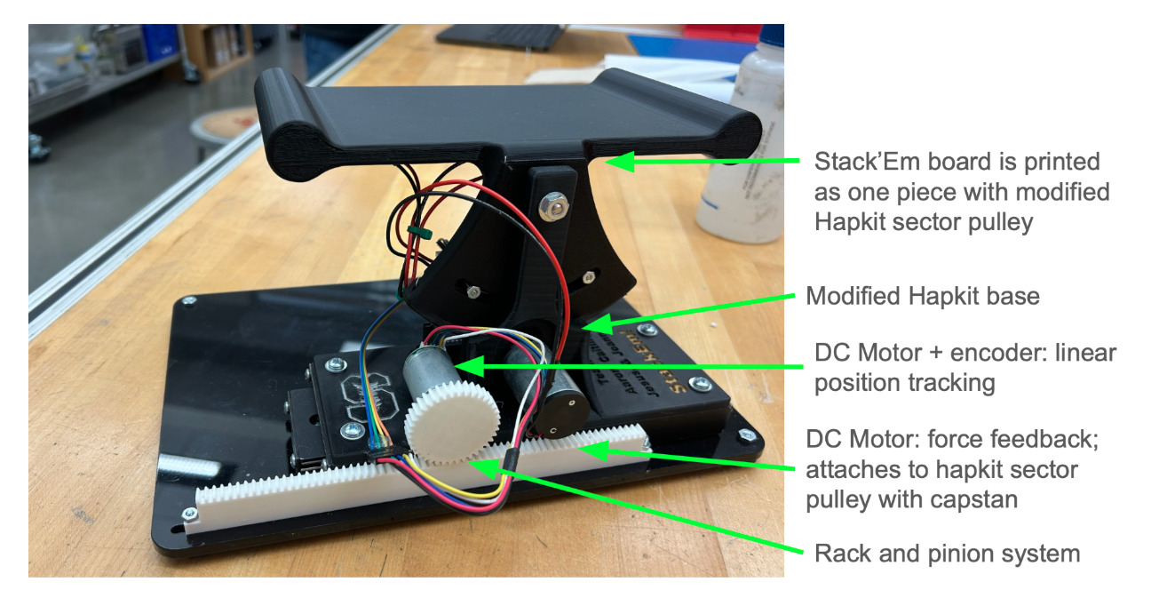
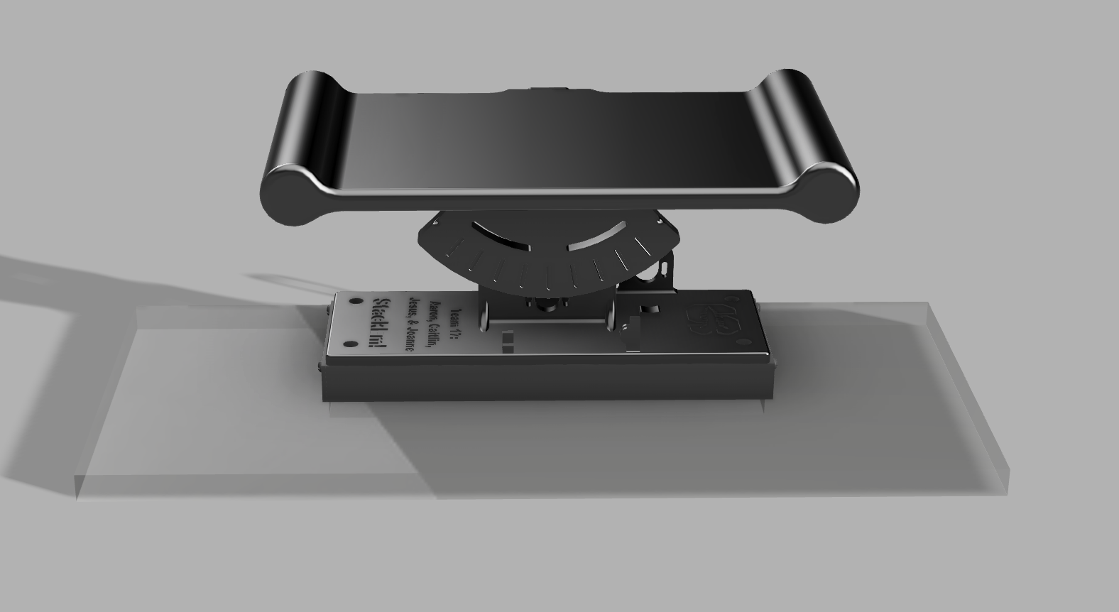
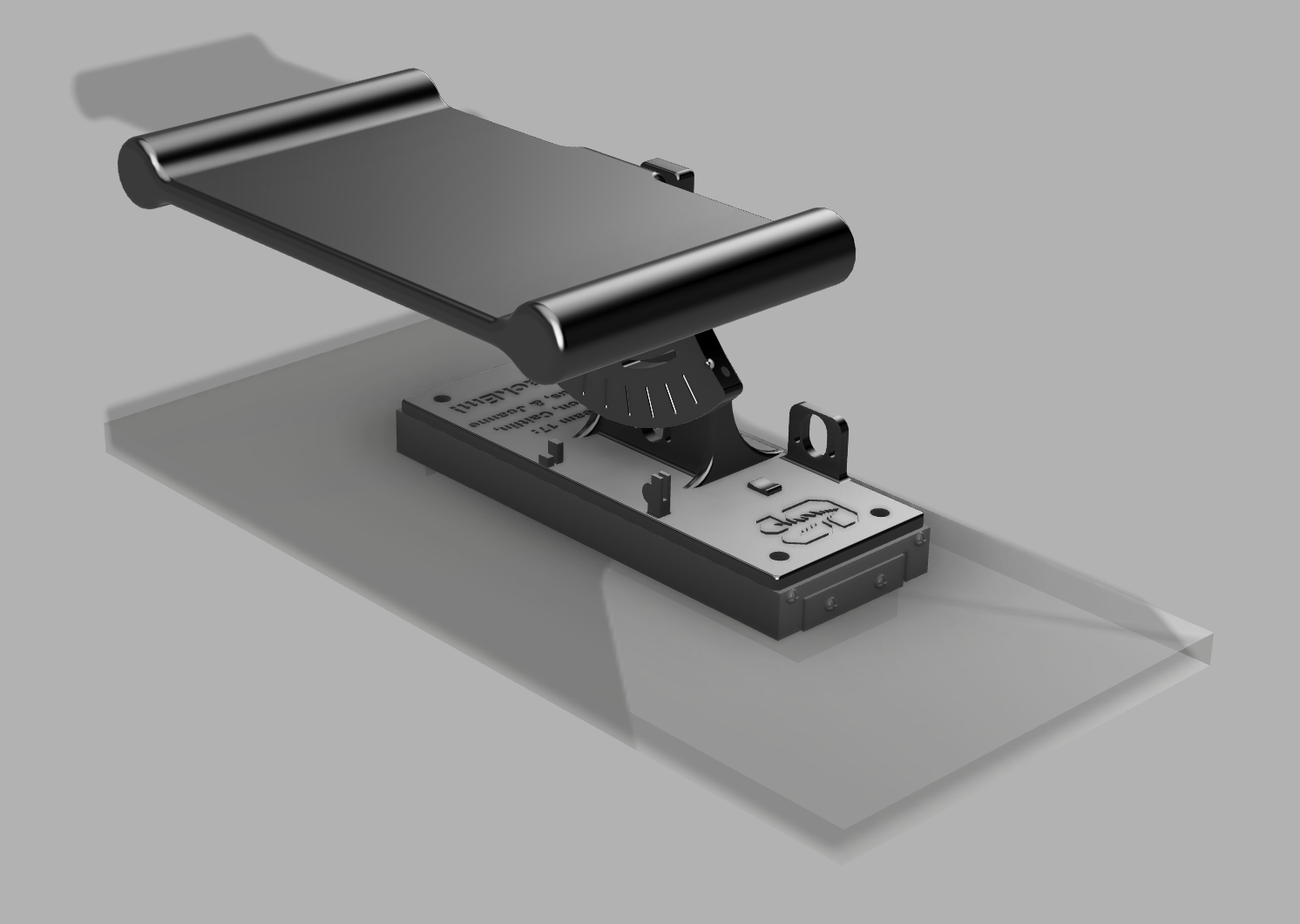
Stack'Em hardware design and components
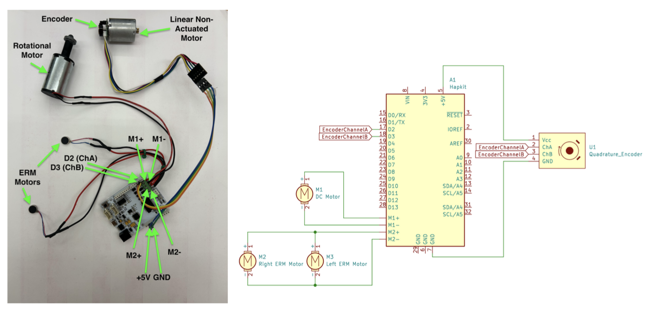
Stack'Em Wiring Diagram
Results
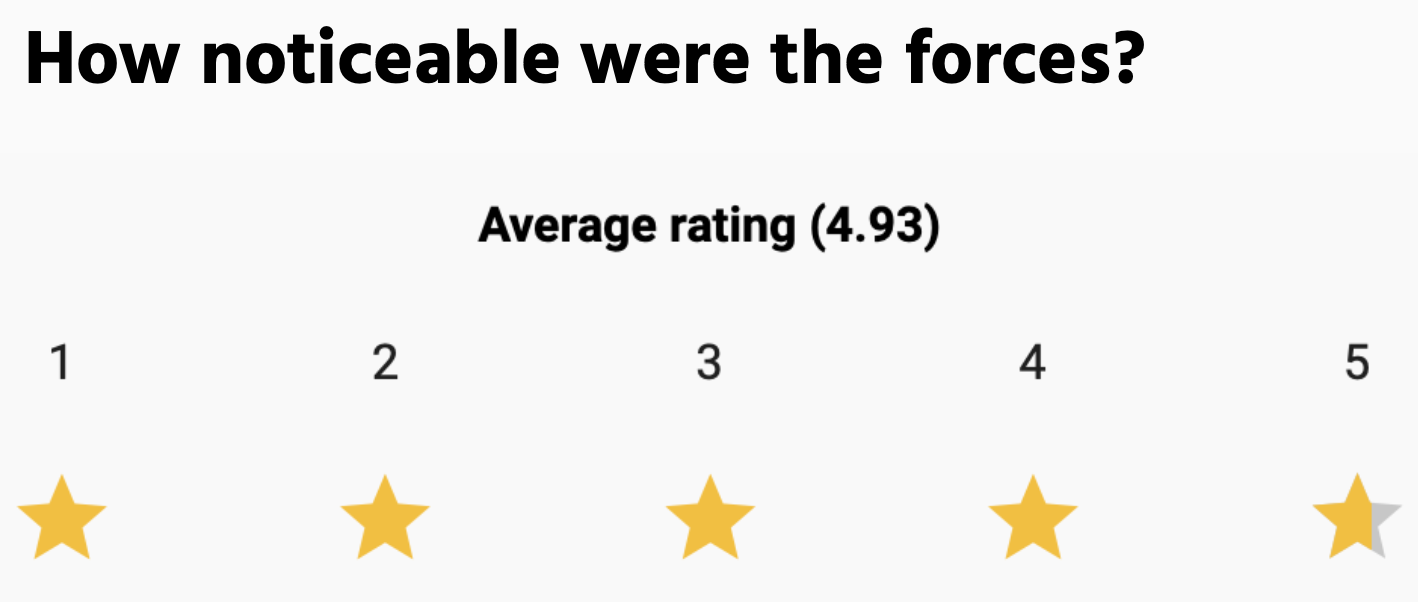
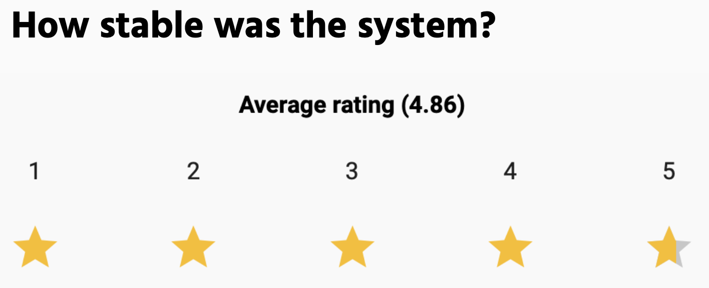
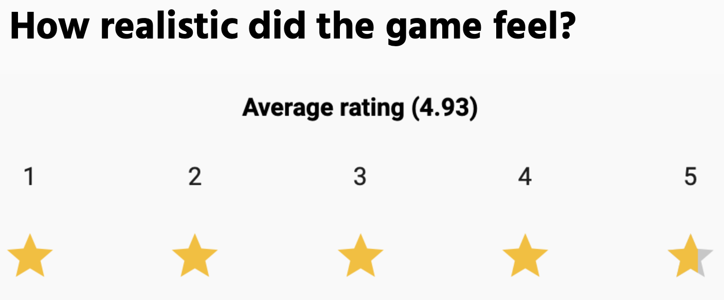
About 75 users tried Stack�Em during the haptics open house, and the system remained stable and functional for each user. The system received overwhelmingly positive feedback, with users citing a "super fun game" that provided a "quality haptic experience" with "really good feedback." 14 users volunteered to complete an anonymous feedback form to rate their experience, and the results are shown below:
Future Work
Testing:
System qualification and reliability could be tested through experiments to discover the limitations of the system, both in terms of hardware and stability. Example questions that we seek to answer include:
→ How repeatable is the haptic feedback across repeated motions?
→ Is there a maximum amount of blocks that can stack before the system becomes unstable?
→ Are there any moments where the haptic feedback feels disconnected from the visual simulation?
→ Are there specific corner cases that cause the system to become unstable?
→ Are there any block collision instances that do not feel realistic to the user?
→ If many many trials are performed, do any hardware components degrade over time?
Improvements:
Based on the results of testing, additional controls could be implemented to reduce any discovered instabilities, such as specific logic to target corner cases. Hardware features can be added to improve the longevity of the system, such as hardstops to prevent over-rotation of the board and a more robust capstan string to prevent slipping. Additionally, an automatic calibration process could be implemented to ensure that the physical board angle consistently matches the rendered board angle before each use, in order to reduce drift and improve accuracy over repeated trials.
To increase the complexity of the system and nuances of the game, additional environments could be programmed with different damping and block weights. For example, in an outer space environment, the blocks would feel lower weight and there would be minimal damping, compared to an underwater environment, where the user would feel higher damping as they try to rotate the board.
Applications:
Applications of this game, beyond providing a fun haptic experience, include its potential use as an educational tool for understanding the effects of gravity, damping, friction, and stability. Because users can physically feel the difference between environments, the system could help make abstract physics concepts more intuitive. For example, students could compare how blocks move in a low-gravity outer space setting versus a high-damping underwater setting, allowing them to connect visual motion with physical resistance.
The system could also be applied in interactive museum exhibits, classroom demonstrations, or physics labs where hands-on learning is valuable. By adjusting variables such as block mass, board angle, damping, or friction, users could experiment with cause-and-effect relationships in real time. This would allow the game to function not only as entertainment, but also as a tool for exploring mechanics, system stability, and human interaction with simulated physical environments.
Acknowledgments
Special thank you to the entire ME327 teaching team --- Professor Allison Okamura, Elizabeth Childs, Megan Coram, and XinYi Liang --- for their ideas, mentorship, and support throughout this class and project.
Files
Code Folder: https://drive.google.com/drive/u/1/folders/1cGYrKIzEah4yroLBnHvNsK7FW6kUPBq0
Materials List: https://docs.google.com/document/d/1rfyLMHOahfJqNoCbeDhGwjy_uE3rCJgwAeZBXxOkO4s/edit?tab=t.0
References
[1] Aksoy, B., Shilati, A., Forbes, B. et al. Strong yet backdrivable robots through capstan-amplified electroadhesive clutches. npj Robot 4, 23 (2026). https://doi.org/10.1038/s44182-026-00084-1
[2] A. Mazumdar et al., "Synthetic Fiber Capstan Drives for Highly Efficient, Torque Controlled, Robotic Applications," in IEEE Robotics and Automation Letters, vol. 2, no. 2, pp. 554-561, April 2017, doi: 10.1109/LRA.2016.2646259. keywords: {Legged locomotion;Torque;Impedance;Pulleys;Steel;Bandwidth;Humanoid and bipedal locomotion;humanoid robots;mechanism design of mobile robots},
[3] van Beek FE, Heck DJ, Nijmeijer H, Bergmann Tiest WM, Kappers AM. The Effect of Global and Local Damping on the Perception of Hardness. IEEE Trans Haptics. 2016 Jul-Sep;9(3):409-20. doi: 10.1109/TOH.2016.2567395. Epub 2016 May 12. PMID: 27187972.
[4] M. Samad, E. Gatti, A. Hermes, H. Benko, C. Parise. 2019. Pseudo-Haptic Weight: Changing the Perceived Weight of Virtual Objects By Manipulating Control-Display Ratio. In Proceedings of the 2019 CHI Conference on Human Factors in Computing Systems (CHI '19). Association for Computing Machinery, New York, NY, USA, Paper 320, 1�13. https://doi.org/10.1145/3290605.3300550
[5] van Polanen V, Tibold R, Nuruki A, Davare M. Visual delay affects force scaling and weight perception during object lifting in virtual reality. J Neurophysiol. 2019 Apr 1;121(4):1398-1409. doi: 10.1152/jn.00396.2018. Epub 2019 Jan 23. PMID: 30673365; PMCID: PMC6485735.
Appendix: Project Checkpoints
Checkpoint 1
- starter UI and preliminary rendering on Hapkit
- finished materials list
- rough prototype of mechanical system
- analysis and dynamics and definition of success
Code
For the starting code of our project, our main goal was to have the rendering of a moving platform and blocks stacking to set up the overall framework of our game. Having this setup is crucial for the future integration of block dynamics and force feedback as we continue to develop our mechanical system. The code we developed take in the Hapkit handle position as an input for the position of the moving platform in the virtual environment. A series of blocks are programed to fall at arbitrary locations and stacks successfully as long as it makes contact with the platform or another block. As we developed the framework for this code, we realized that the integration of block dynamics may be more challenging than we initially thought. One of the foreseeable challenges for the next checkpoint will be the successful integration of block dynamics in the virtual environment and accurate force feedback for the physical system.
Materials List
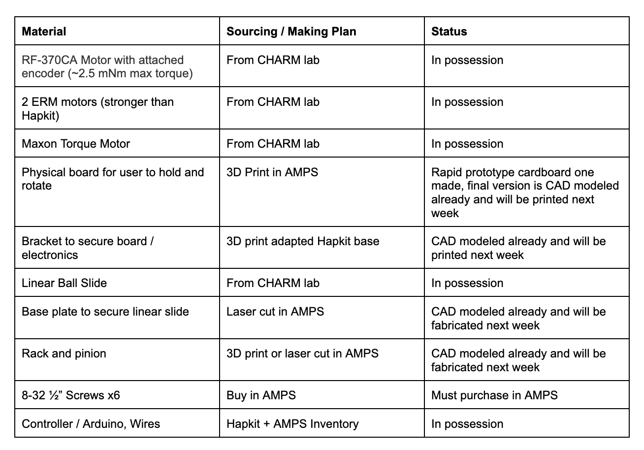
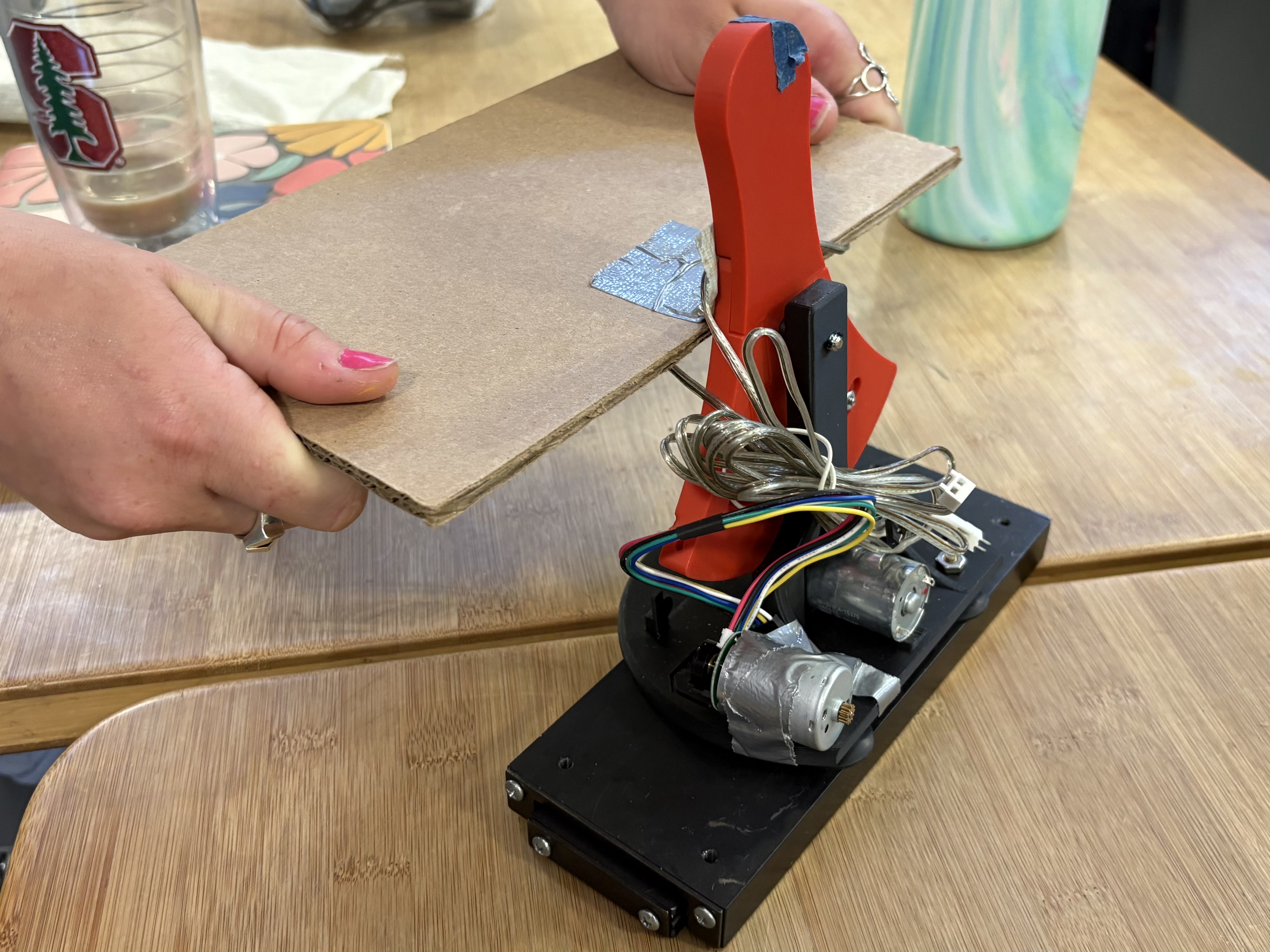
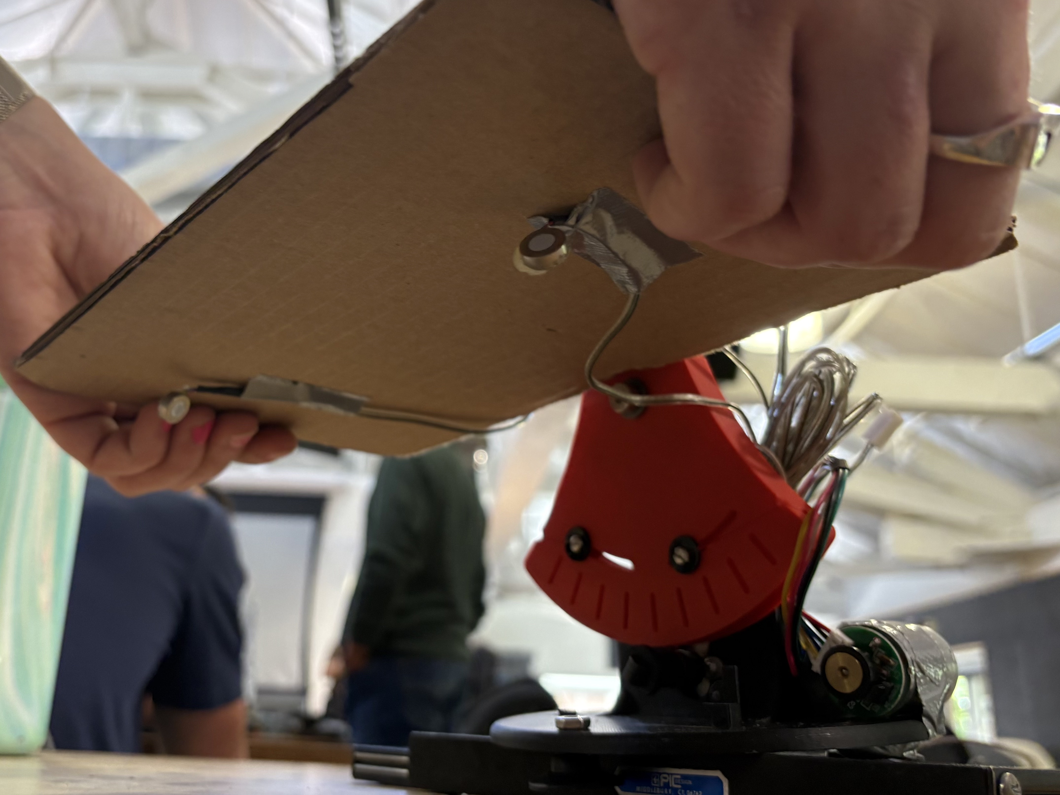
Mechanical System Prototype
Our rough physical prototype consists of a modified Hapkit attached to a linear rail to allow both translational and angular motion. There is a second motor attached to the base of the Hapkit that will be attached to a rack and pinion system to track position in the x direction, while the original motor will track the angular position and provide force feedback to the user. The underside of the platform will contain two ERM motors that will send vibrational feedback when impact is made. Through the creation of this physical prototype, we determined that the optimal platform position should be right above the pivot point, and that the platform should include handles to house the ERM motors for a more transparent sensation.
Preliminary CAD
Based on our learnings from our rough prototype, we designed the system on CAD which features a modified Hapkit base that can screw directly into the linear rail, and a modified Hapkit sector pulley with the added board. The board features round handles for the user to grip onto, and the ERMs will be embedded in the base of these handles. The linear rail will mount onto an acrylic base to keep it in place. These components will be 3D printed and laser cut within the next week as we begin to integrate the full system.
Analysis and Dynamics
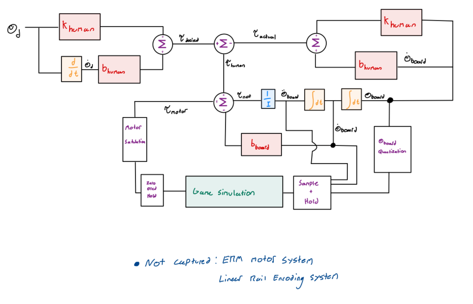
A successful system will provide a convincing feeling of realism in terms of users feeling the dynamics of the block tower and impacts generated by blocks. This translates to users being able to discern, without needing to rely on the GUI, where the tower is located relative to the platform, when falling blocks collide with the platform (or tower of blocks on the board), and how much speed objects had when colliding. The minimum functions the virtual environment should recreate are linear and angular movements of the platform, and should reflect in the blocks motion through the appropriate sliding and colliding dynamics from a penalty based simulation.
In terms of system design, this means finding the highest gain values possible without encountering instability, to create sharp perceivable impacts and object stiffnesses. Alongside this, non-linear effects in the system will have to be accounted for, either by simply being acknowledged and worked around (such as motor saturation), or actively dealt with (ensuring a high sampling time to minimize holds / time-delays).
Checkpoint 2
Thursday May 21st:
- Basic dynamics and implementation
- Integrated electromechanical system (can be buggy)
Basic Blocks Dynamics Analysis
For our current system, we rendered the blocks sliding on the board due to platform acceleration and platform angle. For this checkpoint, we are focusing on full system integration and will work out minor kinks and adding in more advanced dynamics (such as stick-slip transitions, viscous damping) to improve the feedback after this checkpoint. The blocks can rotate and have a defined area that affects their interaction with the other blocks and the board. They can collide with each other and the board.�
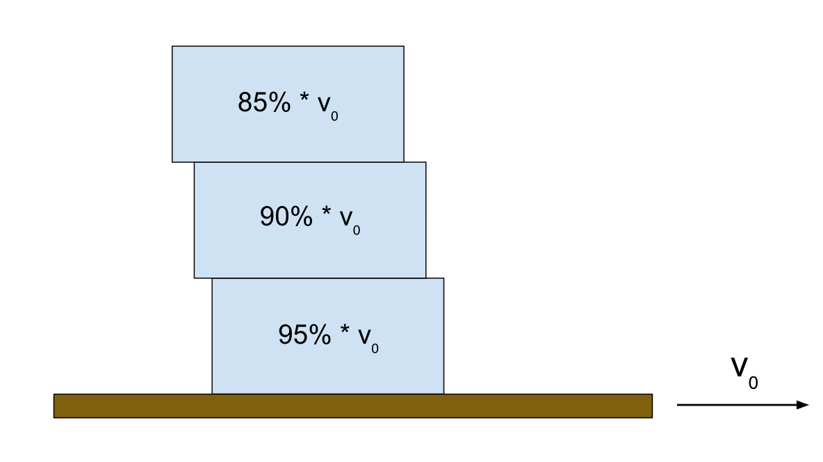
Friction Rendering
To render the frictional force between each block that causes sliding due to platform acceleration as it moves back and forth, each block gets assigned a percentage of the platform velocity which creates a visual "trailing effect".
Center of Mass Calculations
We took the center of mass of each block as the x-distance from the center of the block to the center of the board's rotation axis, in a cartesian XY coordinate system. Since all the blocks have the same mass, the calculation simplifies to the average of these x-distances. The center of mass can then be used to calculate the torque that the blocks apply about the board's axis of rotation, so that we can render these forces to create realistic feedback to the user.
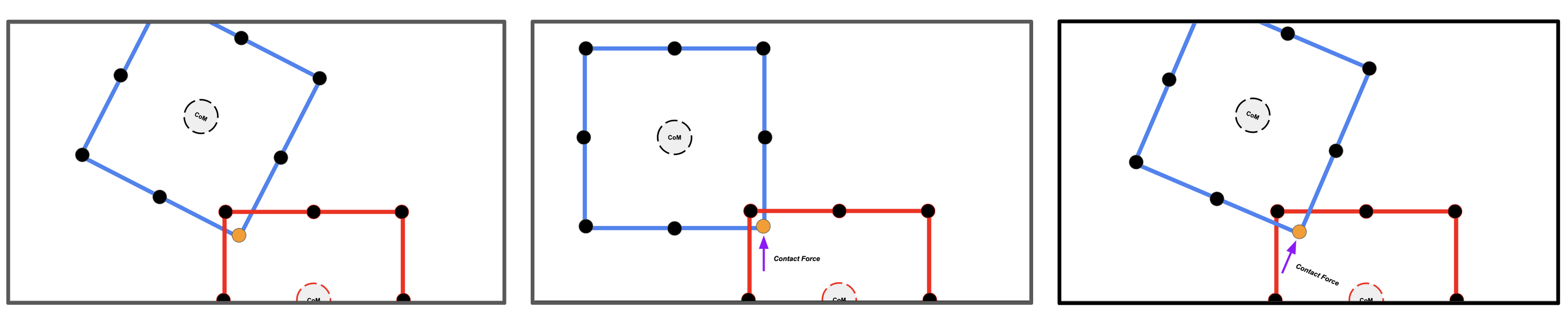
Block Collision & Rotation Rendering
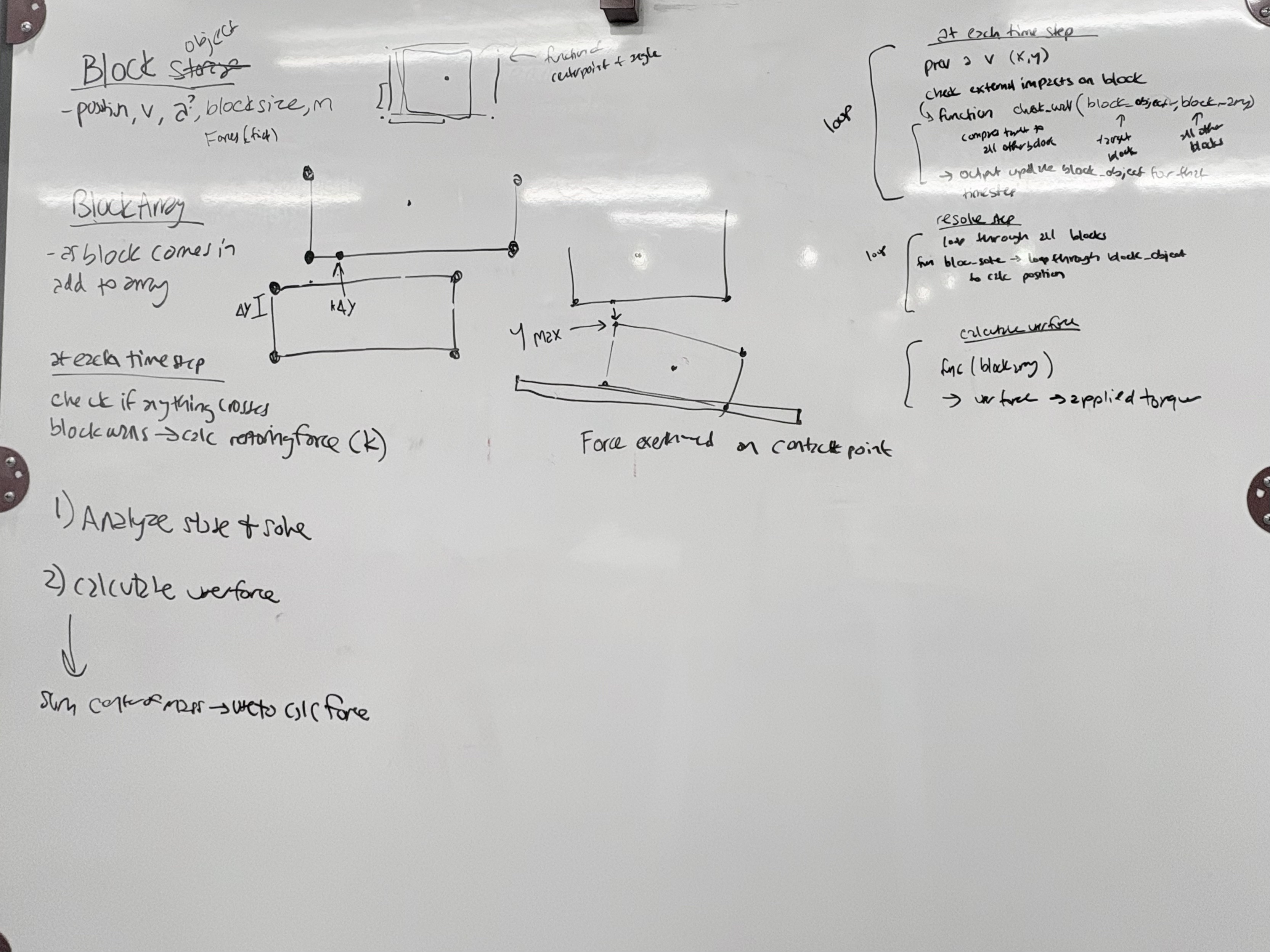
Each block has its boundaries made of 8 points. These points lie at the blocks four corners, and the four midpoints of each side. To render collisions and resultant motion (both angular and linear), we implement a penalty-based method where every block has an assigned stiffness (k) and damping (d) coefficient. During every iteration of the control loop every blocks respective eight points are checked for a collision. The figure below show cases how this is done. We first iterate through every rendered blocks eight points and compare them against all other rendered blocks. If a block's point is found to lie within the bounds of another block (collision block) we proceed to generate a force vector. This is done as follows. If a point is within the bounds of another block we first rotate the current block into the frame of the collision block as either block could be at an arbitrary angle (theta). We then determine the direction of the collision by finding the closest side of the collision block to the current point. The magnitude of the collision force is found by finding the distance to the closest side and multiplying by the collision block's k value. This force vector is either in the local x or y direction only. We then rotate the vector back into the current block's original frame to finalize the collision for that point. This is repeated until each of a block's eight points have an assigned force vector. We then do a summation of forces and moments about the block's CoM to find the resultant force vector and torque. Using the Euler method the blocks position and angle are then updated for the given time step. To avoid an induced torque when only 2/3 points of a side lie on a block (ie when a block is flat on top of another), we artificially "snap" the block to the one below and bypass the natural dynamics.
Implementation of Block Dynamics:
Video of block dynamics: https://youtu.be/wJJB2s9-o2E
Integrated Electromechanical System
For this week's checkpoint, we fabricated the physical board and base to integrate the necessary mechanical features with the Hapkit. We 3D printed an adapted Hapkit base to mate with the linear ball slide, and we printed a board/Hapkit sector piece that rotates about the existing central pivot of the Hapkit. We mounted all of this on an acrylic base plate with rubber feet on the bottom to prevent sliding. A rack and pinion with an encoder attached to the pinion allows us to track the linear travel of the board as it slides from left to right. The rotation of the board is tracked with a magnetic sensor, using the same setup as the initial Hapkit. Next steps for the upcoming week is to implement force feedback and ERM motors into the system .