

2026-Group 18

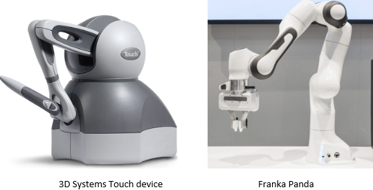
The Project will be executed using The Touch by 3D Systems.
Conceptual image generated with ChatGPT
Haptic Feedback for Fine-Tuning Vision-Language-Action Models
On this page... (hide)
Section 1: Introduction
This project investigates whether haptic force feedback during teleoperation improves the quality of human demonstration data for imitation learning in contact-rich manipulation tasks. The core task is peg-in-hole insertion, where a virtual Franka Panda arm must locate and insert a cylinder into a hole using a 3D Systems Touch haptic device as the control interface. Without force feedback, the operator must rely entirely on visual estimation to judge contact. With haptic feedback, the operator physically feels rim contact and lateral constraint forces in real time, enabling corrective motion that vision alone cannot support.
The central research question is: does haptic force feedback during teleoperation improve human demonstration quality for imitation learning of contact-rich manipulation tasks? Our hypothesis is that haptic feedback reduces task completion time and failure rate by providing contact information unavailable through vision, and that demonstration datasets collected with haptic feedback will produce better fine-tuned policy performance than those collected without.
The project has two components. The primary study compares human teleoperation performance with haptic feedback enabled versus disabled, measuring completion time and task success rate across matched trials. As a hardware contribution, reversible physical attachments for the Touch stylus were designed and fabricated to enhance haptic immersion, without permanently modifying the device.
The Team:
The team consists of two members with complementary expertise. Arya Nair is a manufacturing engineer with hands-on fabrication experience and CAD design skills. She leads the hardware side: design and fabrication of the Touch stylus attachments (hereafter the "Haptic Augmentation Attachments"). Bea Lim is a controls engineer with expertise in control algorithm design. She leads the teleoperation system development and its controls analysis (hereafter the "Teleoperation Haptic Bridge"). As the only fully remote team in the class, both members operated independently from separate locations, making the hardware-software division of work both a practical necessity and a natural fit for individual expertise. Critically, the two workstreams ran in parallel throughout: attachment fabrication and fit-testing proceeded concurrently with software development and controller characterization, with no hard dependency between them until final integration.
Section 2: Background
Haptic teleoperation systems allow a human operator to control a remote or simulated robot while receiving force feedback that reflects the robot's contact with its environment. The closed-loop flow of position commands from operator to robot and force information from robot back to operator is known as bilateral teleoperation. The fidelity of this loop (how accurately forces are transmitted and how closely the robot tracks the operator's motion) determines the system's transparency. A perfectly transparent system would make the virtual environment feel indistinguishable from direct physical contact; in practice, transparency is limited by controller bandwidth, actuation delays, and the fundamental tradeoff between stability and force rendering quality.
The device used in this project is the 3D Systems Touch, an impedance-type haptic device. It interfaces via USB and the OpenHaptics HDAPI, which exposes a 1 kHz servo loop for force rendering. The Touch is widely used in research as a cost-effective ground-truth haptic input device, and has been validated in teleoperation, surgical simulation, and assembly training applications.
Three bodies of prior work are directly relevant to this project.
(1) The most directly related study to our hardware contribution is Zoller et al. (2024), who systematically investigated how handle shape affects operator performance during a virtual peg-in-hole task on a lambda.6 haptic device. Testing nine different handle geometries within subjects, they found that all usability metrics (completion time, motion smoothness, collision force, and perceived workload) changed significantly with handle shape, and that no single design was universally optimal across all metrics. The fixed-hook-grasp handle minimized completion time while the tripod-grasp handle minimized contact force. This is direct experimental evidence for the passive haptic augmentation hypothesis motivating our attachment study: the geometry of what the operator holds changes how they perform contact-rich manipulation, independently of any change to the force rendering itself. Our study mirrors this methodology: within-subjects, objective performance metrics, applied to the specific Touch stylus geometry and peg-in-hole task.
(2) On the data collection side, Cuan, Okamura, and Khansari (2024, IEEE Transactions on Haptics) provide the closest existing work to our primary research question. They augmented a teleoperation system for a mobile manipulator opening door latches with real-time haptic feedback and found that haptic feedback improved data collection throughput by 6% and improved the performance of downstream deep imitation learning policies trained on the collected demonstrations. This is, to the authors' knowledge, the first study to measure the effect of haptic feedback on imitation learning policy performance end-to-end in a real-world setting. The result motivates our study in simulation: if haptic feedback improves demonstration quality for a door-latch task, the effect should be larger for peg-in-hole insertion where contact forces are more informative and more difficult to infer visually.
(3) The most relevant work on the policy learning side is Liu et al. (2025, FACTR), which addresses how to train contact-rich manipulation policies that actually use force information rather than over-relying on vision. FACTR builds a bilateral teleoperation system with force reflection from follower to leader arm and introduces a curriculum training strategy that degrades visual input early in training to force the policy to learn useful force representations first. The key finding for our project is that simply adding force readings to a vision policy is insufficient, the model may ignore force due to modality imbalance. This motivates separating the effect of haptic feedback during data collection (our primary study) from the effect of force as a policy input (a future direction), and focusing our evaluation on tasks with clear contact-phase structure where force is maximally informative.
Section 3: Methods
Subsection 3.1 covers the design and implementation of the Haptic Augmentation Attachment part of the project, and 3.2 details the implementation of the Haptic Teleoperation Bridge and its controls and system analysis.
3.1 Haptic Augmentation Attachment: Design and Implementation
-- Arya Nair --
To investigate the effect of passive haptic augmentation on user experience in a virtual peg-in-hole task, three custom handle attachments were designed, fabricated, and evaluated alongside a no-attachment baseline condition. The design process spanned conceptual ideation, CAD modeling, manufacturing, and physical integration with the 3D Systems Touch haptic device.
3.1.1 Design Rationale
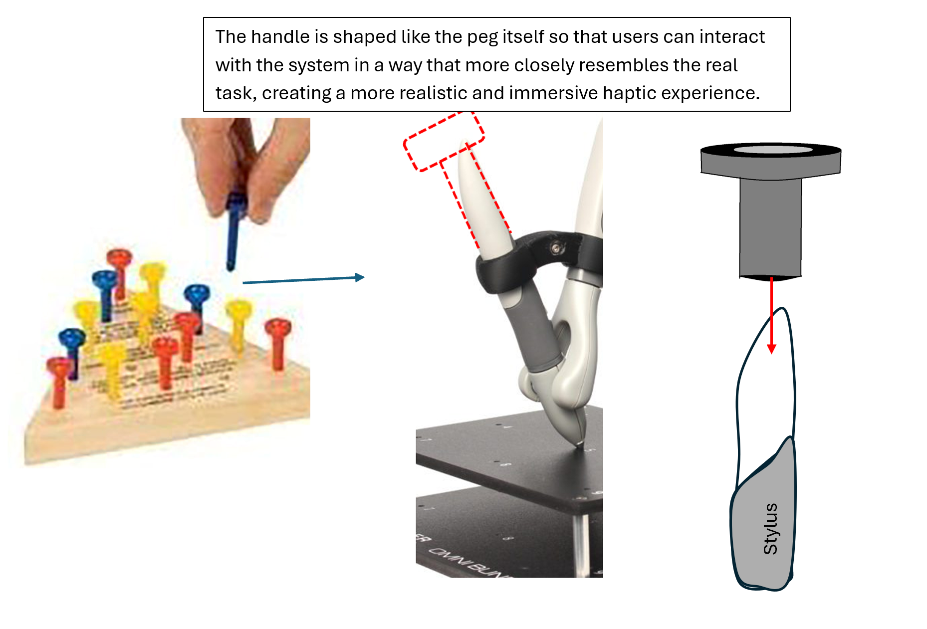
The standard Touch stylus, while functional as a force-feedback interface, provides no physical form cue corresponding to the virtual object being manipulated. In a peg-in-hole task, this creates a sensory mismatch: the user's visual and force feedback channels communicate the presence of a peg, while the tactile and proprioceptive channels receive no corroborating information. This gap motivated the development of passive haptic augmentation attachments — physical handle extensions whose geometry is designed to align with different aspects of the user's haptic expectation, without requiring any modification to the underlying force-rendering software.

Handle designs and Objective.
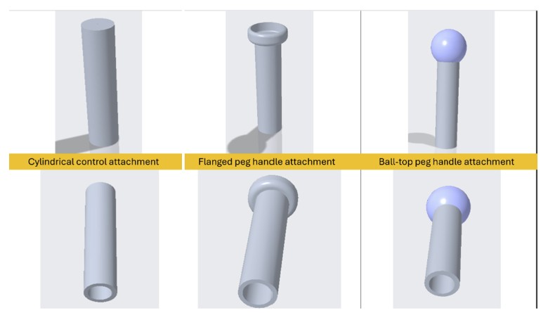
Three distinct design philosophies were pursued. The first targets virtual congruence, matching the geometry of the handle to the cylindrical virtual peg as rendered in the simulation environment. The second targets semantic congruence, matching the handle to the user's real-world conceptual expectation of what a peg looks and feels like, realized through a flanged cap geometry. The third targets ergonomic optimization, departing from strict shape fidelity in favor of a rounded ball-top grip designed to maximize handling comfort. Together, these three conditions form a passive haptic fidelity spectrum that allows the effect of handle geometry to be systematically evaluated across multiple dimensions of congruence.
3.1.2 CAD Modeling
All three attachments were modeled in PTC Creo Parametric. The design process began by establishing a shared set of geometric constraints applicable to all three conditions. Each attachment features a hollow cylindrical bore sized to enclose the Touch stylus handle by approximately 3 inches, with the upper boundary of the attachment sitting just above the two side buttons on the device. This mounting configuration ensures a secure, repeatable fit that requires no hardware modification to the Touch device and can be attached or removed quickly between experimental conditions.
CAD Designs from CREO
A critical design constraint was the standardization of effective tool length across all three conditions. To ensure that the distance between the user's grip point and the device's tool center point remained consistent, all attachments were designed to the same total length. This eliminates lever arm geometry as a confounding variable, ensuring that any observed differences in user performance or preference can be attributed to handle shape rather than differences in reach or contact-point distance.
The three geometries were then developed within these shared constraints. The cylindrical attachment features a uniform circular cross-section with a flat top, providing a neutral grip with no distinctive shape cue beyond its length and diameter. The flanged peg attachment incorporates a flat disk-shaped collar at the top of the cylinder, referencing the characteristic head geometry of an industrial peg and providing a tactile orientation cue at the tip. The ball-top attachment replaces the flat or flanged top with a smooth spherical cap, offering a rounded, palm-filling grip surface that prioritizes tactile comfort over geometric realism.
3.1.3 Fabrication
All three attachments were fabricated using fused deposition modeling (FDM) on a Bambu Lab 3D printer using PLA filament. PLA was selected for its dimensional accuracy, surface finish quality, and ease of post-processing, all of which are relevant to the tactile experience of the handle during use. The attachments were printed at standard resolution with solid infill in the grip region to ensure structural rigidity and consistent feel across units.

Preview from GrabCAD, 3D printing Software.
3.1.4 Integration with the Touch Device
Each attachment was designed to interface directly with the Touch stylus without the use of adhesives or mechanical fasteners. The hollow bore fits snugly over the existing stylus geometry, with the lower rim of the attachment resting just above the two side buttons to provide a consistent seating position. This design allows rapid condition switching during the user study while maintaining positional repeatability across trials. The no-attachment baseline condition was tested with the standard Touch stylus as provided, with no modifications.
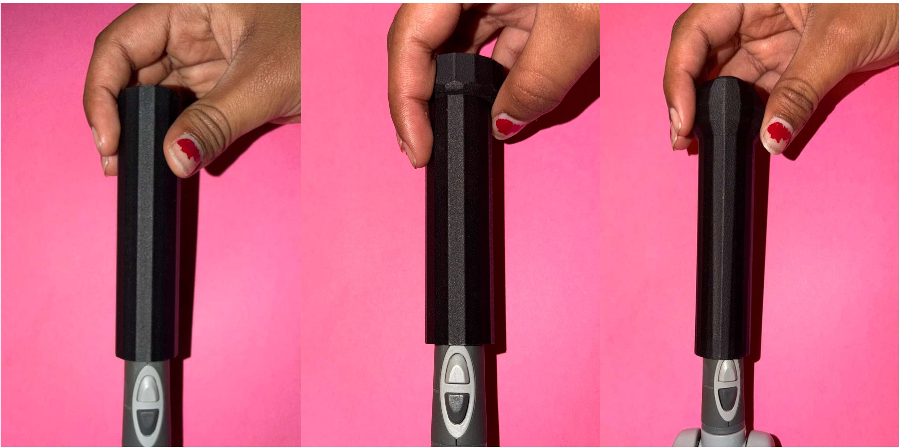
3D Printed Handles under testing
3.1.5 User Study Protocol and Evaluation Methodology
To evaluate the effect of each handle attachment on the user experience, a structured pilot study was conducted with 6 participants. Prior to beginning the study, each participant was asked to complete a brief screening question indicating whether they had any prior physical experience with peg-in-hole tasks. This information was recorded to allow for stratified interpretation of the results. Each participant interacted with all three handle attachments in sequence, with the no-attachment baseline condition also included for physical reference. To ensure participants developed a sufficiently grounded sense of each handle before evaluating it, they were asked to complete the peg-in-hole task three times per attachment before providing any ratings. This repeated trial approach was intended to minimize the effect of novelty bias, where initial unfamiliarity with a handle might skew early impressions, and to allow participants to form a more stable and informed judgment of each design.
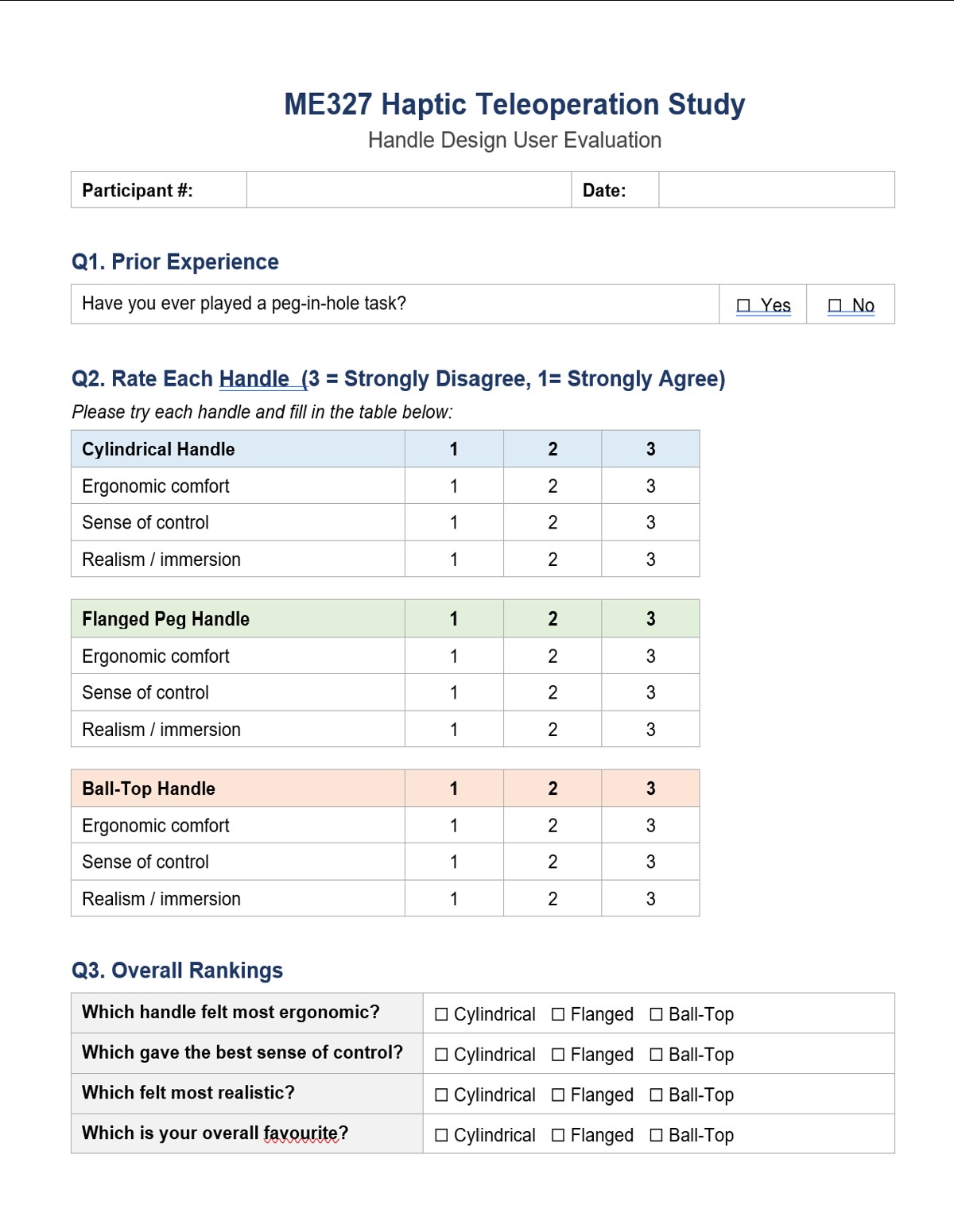
Preview of the Passive Haptic Augmentation Study form
Following the three trials with each attachment, participants completed a structured questionnaire — the Passive Haptic Augmentation Study form. The questionnaire asked participants to rate each handle across three dimensions on a three-point Likert scale: ergonomic comfort, sense of control, and realism/immersion, where 1 indicated strong agreement and 3 indicated strong disagreement with each positive attribute. After rating all three handles individually, participants were asked to select an overall winner across four categories: which handle felt most ergonomic, which gave the best sense of control, which felt most realistic, and which was their overall favorite. These categorical rankings provided a direct preference signal that complemented the Likert scale ratings. The within-subjects design — where every participant experienced all three conditions — was chosen to control for individual differences in motor skill and haptic sensitivity, and to maximize the information obtained from a small pilot sample. The results of this evaluation are presented in Section 4.1.
3.2 Haptic Teleoperation Bridge: Implementation, Controls and System Analysis
-- Bea Lim --
This section first outlines the theoretical models used to describe the teleoperation system, including the control architecture, position-tracking dynamics, and haptic rendering framework (Sections 3.2.1–3.2.4). The experimental procedures used to validate these models are then presented in Section 3.2.5. Experimental results, including teleoperation performance comparisons with and without force feedback, as well as the evaluation of the custom physical attachment designed to enhance immersion during teleoperation, are presented in Section 4.
3.2.1 System Architecture
The teleoperation system links a 3D Systems Touch haptic device to a simulated Franka Panda robot arm running inside the robosuite framework on MuJoCo.
The operator grasps the Touch stylus and motions are mapped in real time to desired end-effector (EEF) positions in the virtual environment.

The robot tracks these targets using an Operational Space Control (OSC) position controller. Contact forces generated within the virtual when the robot's gripper interacts with objects are read from MuJoCo and reflected back to the operator through the Touch device actuators, closing the bilateral force-feedback loop. This architecture forms a closed-loop teleoperation system in which position commands travel from the operator to the robot, while force information travels from the environment back to the operator.
The overall signal flow is shown in the figure below.
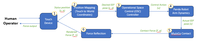
- (1) Sensing: The Touch device measures 3D stylus position at ~1kHz via the OpenHaptics HDAPI.
- (2) Mapping: A position-mapping module converts Touch coordinates (x_h) into desired EEF pose (x_d) within the robot world frame [meters].
- (3) Command: The desired pose is fed to the OSC position controller as a tracking target.
- (4) Control: The OSC control generates joint torques that drive the simulated Panda toward the target.
- (5) Contact: The robot interacts with virtual objects through MuJoCo's constraint-based contact solver.
- (6) Force Reflection: Contact forces (F_e) on the gripper finger geometries are extracted, remapped to the Touch frame, and rendered back to the operator as haptic forces (F_h).
The simulation loop runs at SIM_HZ (nominal at 100Hz) on the main python thread. The haptic callback runs asynchronously at 1kHz on a separate thread managed by the OpenHaptics scheduler. Communication between the two threads is through a shared state dataclass containing the current contact force vector and stylus position.
3.2.2 Teleoperation Control System
3.2.2.1 Position Mapping
The teleoperation interface uses absolute position mapping is used whereby the full Touch workspace is linearly mapped to the robot workspace. The Touch workspace bounds were first measured from the device calibration procedure:
X: [−218.4, +149.5] mm Y: [−112.9, +200.7] mm Z: [−115.2, +89.3] mm
The stylus position is centered, converted to meters and normalized to [-1,1] and scaled by the robot half-range [0.45, 0.45, 0.4] m around the robot's center point set to the EEF home position at reset. Calibration also confirmed the axis correspondence as:
- Touch Z → World X (depth / forward)
- Touch X → World Y (right / left)
- Touch Y → World Z (up / down, MuJoCo Z-up)
3.2.2.2 OSC Controller
The robosuite BASIC composite controller is configured as an OSC_POSE controller operating in the world frame. At each simulation step, the outer position loop computes a position error defined as:
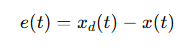
- xd(t) is the desired EEF position derived from the Touch stylus mapping,
- x(t) is the actual EEF position.
The error is scaled by ACTION_GAIN (set at 5.0) and clipped to [-1,1] to produce the normalized action vector sent to the controller:
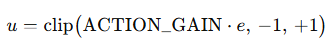
The OSC controller internally converts this action command into joint torques using the robot Jacobian and an inertia-shaping law, with tunable parameters Kp (proportional gain) and damping ratio (fixed throughout the simulation and specified by the osc_world_frame.json file at 400 and 0.2, respectively). The controller runs at the simulation frequency (set at 100Hz). The robot gripper's state is programmed to toggle via the Touch device's Button 1.
3.2.2.3 Force Feedback
Contact forces are extracted for all contacts involving the robot's grippers (right_finger1, right_finger2, finger_pads, hand collision mesh). Environmental object contacts (e.g. objects resting on the table, table on the floor) are explicitly excluded by checking that at least on geometry in each contact pair belongs to the gripper set. The net world-frame force is remapped to the Touch coordinate frame based on the axis correspondence mentioned earlier.
A sign inversion is applied to obtain the force the environment exerts on the gripper. The result is scaled by FORCE_SCALE (0.01, determined during calibration) and clipped to MAX_FORCE_N (2 N), a conservative upper limit chosen to keep forces within a comfortable haptic range, before being written to the shared state. A zero-order hold (ZOH) architecture means the force is constant between simulation steps; at 100 Hz the worst-case stale hold period is 10 ms.
3.2.3 Dynamic Modeling and Stability Analysis
3.2.3.1 Second-Order System Approximation
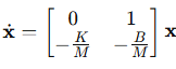
To analyze the tracking lag and stability margins observed during teleoperation, the closed-loop EEF dynamics are approximated as a second order mass-spring damper system. The OSC controller behaves as a virtual impedance controller applying a corrective force:

where
- K is the virtual stiffness,
- B is the virtual damping coefficient,
- xd is the desired end-effector position,
- x is the actual end-effector position.
Rearranging into the standard second-order form with effective mass M:
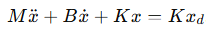
Although the complete robosuite controller and MuJoCo simulator are significantly more complex than this simplified model, the second-order approximation captures the primary dynamics responsible for the observed teleoperation behavior.: the EEF dynamically converges toward the commanded position rather than tracking it instantaneously, introducing phase lag between Touch stylus motion and robot response.
3.2.3.2 State-Space Analysis and Stability Condition
To analyze the stability and responsiveness of the position tracking system, the second-order dynamics can be expressed in state-space form.
The state vector is defined as

where e is the tracking error (xd - x).
The resulting dynamics become
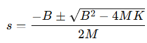
The characteristic equation and corresponding poles are:
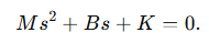
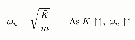
The natural frequency determines the tracking bandwidth of the robot, while the damping ratio determines the amount of oscillation and overshoot.
3.2.3.3 Transparency-Stability Tradeoff
A fundamental constraint in haptic teleoperation is the tradeoff between transparency (the degree to which the remote robot reproduces the operator's intended motion and faithfully transmits the contact forces back to the operator) and stability. Two mechanisms reduce transparency in this system:
Controller bandwidth and tracking lag.
The OSC controller has finite bandwidth determined by ω_n. Stylus motions faster than this bandwidth cannot be faithfully tracked, producing phase lag between the commanded and actual EEF positions. Forces rendered during this lag period do not correspond to the current stylus position, degrading force fidelity and user experience.
Damping-induced force pollution. Part of the force felt by the operator originates from the controller's damping term rather than from contact forces generated by the virtual environment. This introduces non-contact forces into the haptic feedback loop and reduces transparency.
Experimental tuning confirmed this tradeoff. Increasing the OSC controller’s gain Kp from 250 to 400 and reducing the damping ratio from 1.0 to 0.2 significantly improved responsiveness and eliminated the bouncy contact feel observed at higher damping. The bounciness at ζ = 1.0 was caused by tracking lag itself: because the robot took additional timesteps to converge toward the stylus position, the EEF lingered inside the table surface longer than intended, exerting contact forces throughout the extended entry and exit transient. Reducing lag via lower damping caused the robot to track the stylus more tightly, so contact onset and exit happened closer to when the stylus actually touched and left the surface, producing a crisper haptic response. The tradeoff is that at ζ = 0.2, higher-frequency stylus motions now cause visible EEF overshoot, consistent with the reduced stability margin. Increasing SIM_HZ from 20 to 100 Hz also improved contact crispness by reducing the ZOH force update latency, but had a much smaller effect on tracking lag than the damping adjustment, confirming that the dominant source of lag is closed-loop controller bandwidth rather than simulation update rate.
3.2.4 Haptic Rendering and Contact Dynamics
3.2.4.1 Contact Force Extraction and Remapping
At each simulation step, all active contacts involving at least one gripper finger geometry are identified as qualifying contacts. For each one, the MuJoCo API call returns a 6-vector [fx, fy, fz, τx, τy, τz] in the contact local frame.
The world-frame force is remapped to the Touch device frame, as the Touch device axes do not align with the MuJoCo world axes, using the aforementioned mapping, confirmed by calibration experiments. The force is negated to apply Newton's third law for the forces exerted onto the gripper so the operator feels a resistive force opposing penetration, and all qualifying contacts are summed to produce the net contact force.
3.2.4.2 Zero-Order Hold and Force Update Latency
The rendered force is computed once per simulation step (at SIM_HZ = 100 Hz) and held constant until the next step. The 1 kHz haptic callback reads this held value on every servo tick, producing a staircase approximation of the true contact force signal. This zero-order hold introduces a worst-case update latency of 1/SIM_HZ = 10 ms at 100 Hz and a frequency-dependent phase lag of π·f/SIM_HZ radians at signal frequency f. The ZOH −3 dB point is approximately SIM_HZ/π ≈ 32 Hz at 100 Hz, well above the perceptible haptic force bandwidth (~30 Hz for humans), so the ZOH is not the limiting factor for force fidelity at this simulation rate.
The more practically relevant concern is step-change latency during contact onset whereby when the gripper first touches an object, the force can be stale for up to 10 ms before the next simulation step updates it. At 50 Hz simulation rate, this rises to 20 ms, which is within the range of perceptible haptic delay for impulsive contact events.
3.2.4.3 Contact Physics Tuning
MuJoCo contact behaviour is governed by the solref parameter [timeconst, dampratio] on each geometry. The following defaults were calibrated to suitable values for haptic rendering and are applied at runtime via patches:
- Table geoms: solref = [0.02, 2.0] (soft, overdamped: reducing table bounce)
- Finger and hand collision geoms: solref = [0.01, 2.0] (stiffer, overdamped: for a firmer grip on objects)
Table friction was set to (2.0, 0.02, 0.001) and cylinder friction to (3.4, 0.3, 0.01) (sliding, torsional, rolling) to provide stable grasp without excessive slip.
3.2.5 Transparency and Performance Evaluation
A suite of open-loop characterization experiments was conducted via a test script (osc_tests.py) that drives the simulated Panda arm with programmatic position targets (step functions and sinusoidal trajectories) without any Touch device input. This isolates the robot controller performance from operator variability. All experiments used ACTION_GAIN = 5.0 at SIM_HZ = 100 Hz (same configuration as the calibrated teleoperation system) unless otherwise noted. The EEF was initialized to a fixed starting configuration/position = [0, −0.785, 0, −2.356, 0, 1.571, 0.785] and allowed 50 warm-up steps before recording began. The EEF start position is used as the reference origin for all step targets.
3.2.5.1 Step Response Characterization
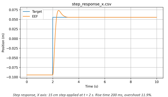
Step inputs of X, Y, Z = [15, 20, 20] cm were applied at t=2s. Each experiment ran for 10 s total. Rise time, settling time (±2% band), percentage overshoot, and steady-state error were computed from the logged EEF position.
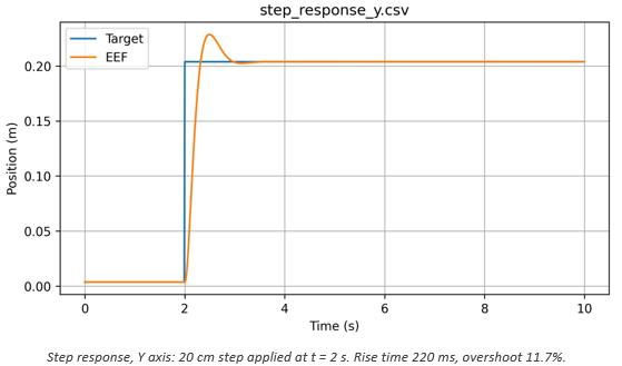

The table below summarizes the measured metrics across all three axes.
| Axis | Step size | Rise time (10-90%) | Settling time (2%) | Overshoot | Steady-state error |
|---|---|---|---|---|---|
| X | 15 cm | 200 ms | 890 ms | 11.9% | <0.1 mm |
| Y | 20 cm | 220 ms | 850 ms | 11.7% | <0.2 mm |
| Z | 20 cm | 250 ms | 830 ms | 5.9% | <0.1 mm |
All three axes exhibit fast rise times (200–250 ms) and near-zero steady-state error, confirming accurate position tracking at steady state. The X and Y axes show ~12% overshoot while the Z axis shows only ~6%. The lower Z overshoot is consistent with gravity compensation reducing the effective inertia in the vertical direction, giving the OSC controller a smaller effective mass to accelerate. The 12% overshoot on X and Y has a direct consequence for peg-in-hole teleoperation: a sudden lateral stylus displacement will cause the EEF to overshoot the intended target by approximately 2–3 cm before correcting, which can cause misalignment during fine insertion.
3.2.5.2 Frequency Response and Bandwidth
To characterise the system bandwidth, sinusoidal targets with amplitude 5 cm were applied along the Y axis at frequencies f = 0.5, 1.0, 2.0, 3.0, and 5.0 Hz. Each experiment ran for 20s. Amplitude gain and phase lag were computed from the steady-state portion only (first two full cycles discarded to eliminate startup transients, which otherwise overestimates the amplitude).
Gain was computed as the ratio of EEF amplitude to target amplitude in the steady-state window. Phase lag was estimated via cross-correlation of the mean-subtracted EEF and target signals.
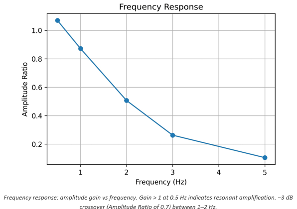
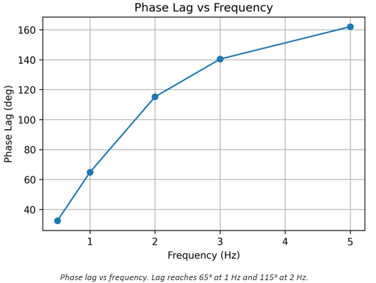
The gain is approximately 1.08 at 0.5 Hz, indicating slight resonant amplification at low frequencies. This is consistent with the ~12% step overshoot whereby both reflect the underdamped character of the closed-loop system at ζ = 0.2. The −3 dB bandwidth (gain = 0.707) falls between 1 and 2 Hz, interpolating to approximately 1.5 Hz. Phase lag grows rapidly: 33° at 0.5 Hz, 65° at 1 Hz, 115° at 2 Hz, and 162° at 5 Hz. The figure below shows these values with the 90° stability limit annotated.
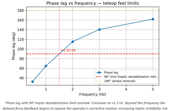
The 90° phase lag crossover at ~1.5 Hz is the practical upper bound for stable haptic teleoperation with this controller configuration. Beyond this frequency the reflected force is a quarter-cycle out of phase with the stylus position, meaning the operator feels resistance (push) while withdrawing and assistance (pull) while penetrating, the opposite of the intended behaviour. Human hand movements during exploratory and precision insertion tasks typically span 0.5–2 Hz, placing the system at or near this limit during active manipulation. Operators should therefore make slow, deliberate approach motions when teleoperating in this system.
3.2.5.3 Damping Ratio Sweep
The OSC damping ratio ζ was swept over [0.2, 0.5, 1.0, 2.0] to characterize its effect on both types on inputs: step and sine (in Virtual Environment Y axis). Step inputs of 20 cm along Y were used for the transient comparison; 0.5 Hz sinusoidal inputs with 5 cm amplitude were used for the sine comparison. Sine tests ran for 10 s with the first 2 cycles discarded.
According to the figure below, the step response overlays shows that all four damping ratios produce essentially identical transient responses. The step input saturates the action output (±1.0) for most of the transient, so the controller runs at maximum effort regardless of damping ratio. The damping parameter only influences the response once the error is small and the action is no longer clipped, by which point the arm is already near the target. This explains why all four damping ratios produce nearly identical step responses
The sine overlay above reveals a clearer trend: phase lag increases monotonically with ζ from 150 ms to 180 ms, and peak tracking error is lowest at ζ = 0.2. Although the 30ms lag range is modest in absolute terms, the direction is consistent with the subjective experience of reduced lag at lower damping reported during haptic teleoperation trials. The lower damping also produces slightly higher EEF amplitude (EEF tracks closer to full target amplitude), which improves transparency. Based on these results, ζ = 0.2 is recommended as the operating point: it provides the lowest phase lag and best sine tracking without any degradation in step settling behavior.
3.2.5.4 Simulation Rate Sweep
The simulation frequency SIM_HZ was swept over [10, 20, 50, 100] Hz while tracking a 0.5 Hz sinusoidal target with 5 cm amplitude along Y for 20 s. RMS position error and peak error were recorded.

Increasing SIM_HZ from 10 to 100 Hz reduces RMS tracking error from 34.0 mm to 20.2 mm (a 41% improvement). The improvement is largest at the low end (10 to 20 Hz: -5.5mm) and smallest at the high end (50 to 100 Hz: −2.7mm), indicating strongly diminishing returns above 50 Hz. For position tracking accuracy alone, 50 Hz provides ~80% of the benefit of 100 Hz. However, simulation rate has a secondary and arguably more important effect on haptic rendering: it determines the ZOH force update latency (worst case = 1/SIM_HZ). At 50 Hz this is 20ms; at 100 Hz it is 10ms. For impulsive contact events, the first moment the peg touches the hole rim, a 20ms stale force window means the operator cannot feel the contact onset for up to one full 50 Hz step. At 100 Hz this is halved. The subjective improvement in contact crispness between 50 and 100 Hz was noted during teleoperation calibration, consistent with this analysis. 100 Hz was selected as the operating rate.
3.2.5.5 Cross-Axis Coupling
Cross-axis coupling measures unintended EEF displacement in axes orthogonal to a commanded step. For a peg-in-hole task this is important as a lateral drift during a vertical (Z) insertion approach can prevent the peg from engaging the hole. The off-axis displacement was computed relative to the pre-step baseline (average of 50 samples before the step) and expressed in mm.
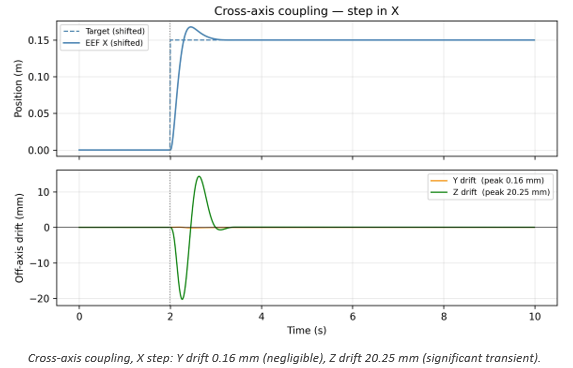
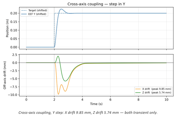
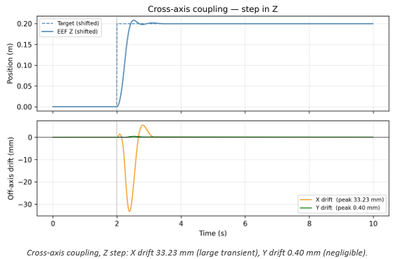
The results reveal a consistent X-Z coupling pattern: a step in X produces a 20 mm transient Z drift, and a step in Z produces a 33 mm transient X drift. Y–Z coupling is moderate (5.7 mm during Y step), and X-Y and Y-Z coupling is negligible (<1 mm). All coupling is entirely transient (the off-axis displacement returns to within 0.5 mm of baseline within 2s of the step) confirming that good steady-state cross-axis decoupling. The coupling arises from the Jacobian-based OSC controller distributing error corrections across joints in a way that transiently excites off-axis DOFs. The X-Z coupling is particularly significant because the primary insertion motion is along Z (downward), and a 33mm transient X drift during a fast Z approach would prevent engagement with a peg hole of typical radius 2.75 cm. The recommended mitigation is slow, deliberate approach motions so that the cross-axis transient decays before contact is attempted.
3.2.6 Summary of Controller Characterization
The table below summarizes the key performance metrics and recommended operating parameters:
| Metric | Value | Notes |
|---|---|---|
| Rise time (step) | 200–250 ms | All axes; Z fastest due to gravity compensation |
| Settling time (2% band) | 830–890 ms | All axes |
| Overshoot (X/Y) | ~12% | ~2–3 cm absolute on 15–20 cm steps |
| Overshoot (Z) | ~6% | Lower due to gravity compensation |
| Steady-state error | <0.2 mm | All axes; excellent for precision insertion |
| Peak EEF speed | 0.66–0.83 m/s | During step transient; controller saturates |
| Bandwidth (−3 dB) | ~1.0–1.5 Hz | Gain-corrected estimate; ≈1.0 Hz conservative |
| 90° phase lag crossover | ~1.5 Hz | Practical haptic stability upper bound |
| Cross-axis drift (Z step) | 33 mm transient | X axis; returns to baseline within 2 s |
Recommended controller parameters based on all characterization experiments are tabulated below:
| Parameter | Recommended value | Rationale |
|---|---|---|
| Kp (OSC stiffness) | 200–250 | Minimum sine-tracking error; no benefit above 300 |
| Damping ratio ζ | 0.2 | Lowest phase lag (150 ms at 0.5 Hz); no transient degradation |
| SIM_HZ | 100 Hz | Best ZOH latency (10 ms); diminishing returns above this |
| ACTION_GAIN | 5.0 | Tested value; higher gain risks oscillation on large errors |
| Max approach speed | <0.1 m/s | Keeps cross-axis coupling below peg–hole clearance (~5 mm) |
| Usable motion bandwidth | ~1.0–1.5 Hz | Phase lag <90°; above this haptic destabilisation risk |
Section 4: Results
Section 4.1 evaluates the effect of the physical stylus attachment, and Section 4.2 evaluates the effect of haptic force feedback on teleoperation performance.
4.1 Haptic Augmentation Attachment Results
-- Arya Nair --
The user evaluation was conducted with 6 participants, 2 of whom reported prior physical experience with peg-in-hole tasks. Each participant tried all three handle attachments — the cylindrical handle, the flanged peg handle, and the ball-top handle — and rated each across three dimensions: ergonomic comfort, sense of control, and realism/immersion. Participants then selected an overall favorite.

Collected Data from Passive Haptic Augmentation Study.
4.1.1 Ergonomic Comfort Across all 6 participants, the ball-top handle was the dominant preference for ergonomic comfort, selected by 5 out of 6 participants. The flanged peg handle was preferred by 1 participant, while the cylindrical handle received no votes in this category. This result is consistent with the design intent of the ball-top attachment, which prioritized grip comfort over shape fidelity. The rounded spherical cap geometry appears to distribute grip pressure more naturally across the palm, making it the most physically comfortable option for the majority of users regardless of their prior experience.

Distribution of participant preferences for ergonomic comfort across the three handle conditions (n=6).
4.1.2 Sense of Control For sense of control, the ball-top handle again led with 4 out of 6 participants selecting it as the handle that gave them the greatest sense of precision and control during the task. The flanged peg handle was preferred by 2 participants in this category, while the cylindrical handle received no votes. The flanged peg's performance here is notable — the disk collar at the top of the handle may provide a tactile orientation reference that benefits users who are already familiar with what a peg should feel like, giving them a clearer sense of where the tip of the tool is during insertion.
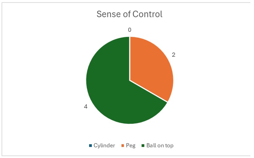
Distribution of participant preferences for sense of control across the three handle conditions (n=6).
4.1.3 Realism and Immersion The realism category produced the most evenly distributed result. Both the flanged peg handle and the ball-top handle each received 3 out of 6 votes, while the cylindrical handle received none. This split is particularly meaningful when interpreted alongside the prior experience data. The 2 participants with real-world peg-in-hole experience both selected the flanged peg as the most realistic, consistent with the hypothesis that semantic congruence — matching the handle to a real-world mental model of a peg — drives perceived realism for experienced users. The remaining 4 participants, lacking that physical reference, rated the ball-top as equally or more realistic, suggesting that for novice users, comfort and naturalness of grip contribute to their subjective sense of immersion.
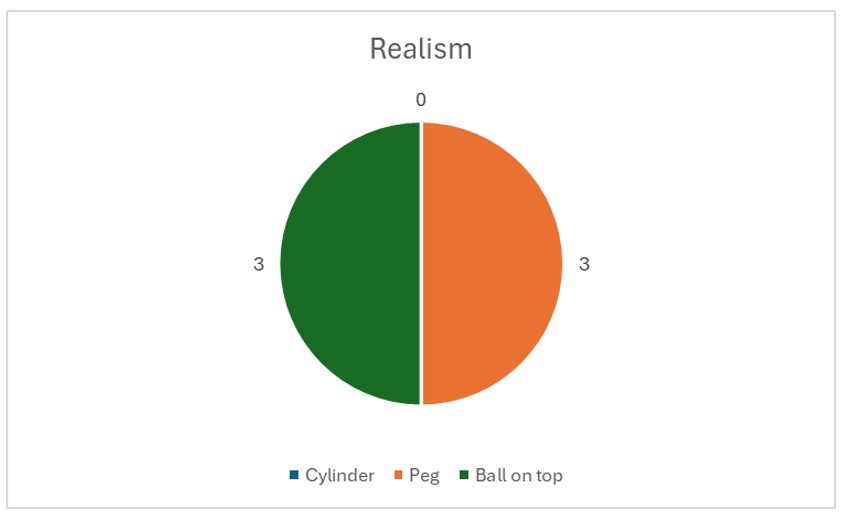
Distribution of participant preferences for realism and immersion across the three handle conditions (n=6).
4.1.4 Overall Favorite When asked to select an overall favorite handle, 4 out of 6 participants chose the ball-top handle and 2 out of 6 chose the flanged peg handle. The cylindrical handle received no votes in any category across the entire evaluation. This result confirms that while the cylinder served its purpose as a geometric control condition, it did not offer a meaningfully improved haptic experience over the other two designs on any evaluated dimension. The overall preference pattern aligns closely with the prior experience split in the participant pool. The 2 participants with prior physical experience with peg-in-hole tasks both preferred the flanged peg handle, gravitating toward the design with the highest semantic congruence to their existing embodied knowledge. The 4 participants without prior experience consistently preferred the ball-top handle, defaulting to ergonomic comfort in the absence of a real-world reference to compare against. This user-dependent preference pattern is the central finding of the haptic augmentation evaluation.

Distribution of participant preferences for overall favorite across the three handle conditions (n=6).
4.2 Haptic Force Feedback: Pilot Teleoperation Performance Study
-- Bea Lim --
4.2.1 Experimental Design
| Design element | Detail |
|---|---|
| Task | Cylinder peg-in-hole insertion; cylinder must be fully seated upright, gripper then releases |
| Success criterion | Cylinder seated and stable upon gripper release; no lateral drop or impact-driven insertion |
| Primary metric | Task completion time per successful trial (s) |
| Conditions | A: haptic feedback enabled, B: haptic feedback disabled |
| Condition order | ABABAB alternating, counterbalanced between participants |
| Participants | N = 2 |
| Trials per participant | As many as time allows |
| Device | 3D Systems Touch, absolute position mapping mode |
The study measures whether haptic force feedback improves human teleoperation performance on a peg-in-hole insertion task. The task requires the operator to pick up a cylinder using the virtual gripper and insert it fully upright into the round nut hole. A trial is considered successful only when the gripper releases the cylinder and it remains fully seated and upright in the hole. Lateral dropping or "whacking" the cylinder in is not allowed. Task completion time is the primary performance metric.
Two participants completed as many trials as possible in an ABABAB alternating condition order, where A = haptic feedback enabled and B = haptic feedback disabled (or vice versa, counterbalanced between participants). The alternating design controls for learning curve and session fatigue effects: if performance improves over time due to practice, the improvement is distributed equally across both conditions rather than benefiting whichever condition happens to come later.
Completion time was chosen as the sole metric for practical reasons: with N = 2 participants and a limited number of trials, a single objective measure avoids the statistical power issues that would arise from splitting attention across multiple metrics. Completion time is also directly interpretable: a faster insertion reflects better contact sensing and correction, which is precisely what haptic feedback is hypothesized to provide.
4.2.1 Teleoperation Performance Results
A total of 70 trials were collected across 2 participants (35 per condition: force feedback enabled/disabled), with completion times summarized below:
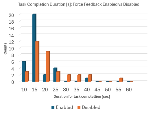
| Force Feedback | Average of Duration |
|---|---|
| Disabled | 18.81 |
| Enabled | 14.29 |
The time taken to complete the peg-in-hole (PiH) task is reduced when force feedback is enabled during teleoperation (by 24% = 4.5s). This pilot study indicates that haptic feedback does help with teleoperation performance and user experience through haptic guided manipulation. Trials with force feedback enabled also has a lower spread than trials with force feedback disabled which shows a broader spread toward longer durations.
Section 5: Future Work
Subsection 5.1 describes the improvements for the design and implementation of the Haptic Augmentation Attachment, and 3.2 notes the improvements for the Haptic Teleoperation Bridge and Teleoperation User Study.
5.1 Haptic Augmentation Attachment Improvements
-- Arya Nair --
While the pilot study presented in this work provides promising directional findings, several avenues exist for expanding and strengthening the evaluation methodology, refining the handle designs, and broadening the scope of the research.
Controlled Prior Experience Study
One of the most compelling findings of the pilot study was the relationship between prior physical experience with peg-in-hole tasks and handle preference. To rigorously investigate this relationship, a future study should deliberately recruit two equal and independent participant groups: one group with documented prior experience performing physical peg-in-hole tasks, and a second group with no prior experience whatsoever and no practice trials before testing. Critically, the experienced group would complete the study without any warm-up either, ensuring that the only difference between groups is their pre-existing embodied knowledge rather than in-session practice effects. By controlling for this variable systematically, it would be possible to establish a statistically meaningful correlation between prior physical experience and passive haptic congruence preference — moving the finding from an observation in a pilot study to a generalizable principle in haptic interface design.
Age-Dependent Haptic Preference Study
A further dimension worth investigating is whether the relative importance of virtual congruence, semantic congruence, and ergonomic comfort varies across age groups. Younger users, typically aged 20 to 30, are more likely to have grown up with digital interfaces and virtual environments, potentially making them more attuned to virtual congruence as a driver of immersion. Older users, in the 70 to 80 age range, may have accumulated greater real-world manual task experience but also experience age-related changes in tactile sensitivity and grip strength, which could shift preference toward ergonomic comfort regardless of shape fidelity. A comparative study across these two age groups using the same three handle conditions and evaluation protocol would reveal whether haptic augmentation design should be age-adaptive — an important consideration for applications of haptic teleoperation in healthcare, rehabilitation, and assistive technology.
Controlled Prior Experience Study
Perhaps the most significant hardware improvement for future iterations would be the transition from passive to active haptic augmentation. In the current design, the handle attachments are purely passive — they shape the user's grip experience but have no electronic functionality of their own. A natural next step would be to integrate the Touch device's side button controls directly into the custom handle geometry, such that the buttons are repositioned to sit naturally under the user's fingers in the new grip configuration rather than remaining on the original stylus body. Beyond button relocation, this direction opens the possibility of embedding additional actuators — such as vibrotactile motors or pressure sensors — directly into the handle, enabling the attachment itself to render supplementary haptic feedback that complements the force output of the Touch device. This would represent a transition from passive haptic augmentation to a fully active augmented handle system, significantly expanding the range of haptic sensations that can be communicated to the user and warranting a new comparative study against the passive conditions evaluated here.
5.2 Haptic Teleoperation Bridge + User Study Improvements
-- Bea Lim --
System / Control
- Orientation control: the current bridge only maps 3-DOF position. Adding wrist orientation would improve insertion alignment for non-vertical approaches.
- Implementing a relative mapping mode where stylus displacement from a neutral home position drives EEF velocity rather than absolute position, analogous to joystick control, to allow finer positional control during the insertion phase by decoupling workspace range from precision.
Experiments
- Recruit a larger participant sample (N ≥ 10) to achieve sufficient statistical power for hypothesis testing, as the current N = 2 pilot study can identify trends but cannot distinguish a true condition effect from individual performance variability.
VLA Integration
- Establish a SmolVLA pretrained baseline on the peg-in-hole task in the virtual environment setup.
- Collect matched demonstration datasets under three conditions: no haptic feedback, haptic feedback enabled, and haptic feedback with peg-shaped attachment.
- Fine-tune SmolVLA separately on each dataset and compare the three fine-tuned policy variants against the pretrained baseline.
Section 6: Acknowledgments
We would like to thank Professor Allison Okamura and the teaching staff, particularly XinYi Liang, for their guidance and support throughout the course. We also gratefully acknowledge the accommodation extended to us as remote part-time students, and the generous provision of Touch devices, which made this project possible. We would like to thank Wyatt Kitzmiller for assisting us with 3D printer resources as well as all our six participants for Passive Augmentation Study for their valuable time and support. We also thank our user study participant, Brian Munoz, for his time.
Section 7: Files
7.1 Haptic Augmentation Attachment
-- Arya Nair --
All aggregated data and questionnaire findings are presented in Section 4.1. Individual participant-level results are not included in this report in accordance with participant privacy considerations. Requests for further data regarding the physical attachment may be directed to Arya Nair.
7.2 Haptic Teleoperation Bridge
-- Bea Lim --
All relevant files and instructions for setting up the Haptic Teleoperation Bridge and running the controls characterization scripts can be found at https://github.com/bealim17/ME327-TouchDevice-Robosuite
Initial demonstration video prior to further OSC tuning for improved responsiveness: Watch demo video
Section 8: References
- [1] Zoller, E. I., von Ballmoos, S., Gerig, N., Cattin, P. C., & Rauter, G. (2024). Handle shape influences system usability in telemanipulation. Frontiers in Robotics and AI, 11, Article 1457926. https://doi.org/10.3389/frobt.2024.1457926
- [2] Cuan, C., Okamura, A., & Khansari, M. (2024). Leveraging haptic feedback to improve data quality and quantity for deep imitation learning models. IEEE Transactions on Haptics, 17(2). https://doi.org/10.1109/TOH.2024.3384482
- [3] Liu, J. J., Li, Y., Shaw, K., Tao, T., Salakhutdinov, R., & Pathak, D. (2025). FACTR: Force-attending curriculum training for contact-rich policy learning. arXiv preprint, arXiv:2502.17432. https://arxiv.org/abs/2502.17432
- [4] Huang, B., et al. (2024). VT-Refine: Learning bimanual assembly with visuo-tactile feedback via simulation fine-tuning. Conference on Robot Learning (CoRL). https://binghao-huang.github.io/vt_refine/vt_refine_corl_camera_ready.pdf
- [5] MuJoCo. Todorov, E., Erez, T., & Tassa, Y. (2012). MuJoCo: A physics engine for model-based control. 2012 IEEE/RSJ International Conference on Intelligent Robots and Systems (IROS), pp. 5026–5033. https://doi.org/10.1109/IROS.2012.6386109
- [6] robosuite. Zhu, Y., Wong, J., Mandlekar, A., Martín-Martín, R., Joshi, A., Nasiriany, S., & Zhu, Y. (2020). robosuite: A modular simulation framework and benchmark for robot learning. arXiv preprint, arXiv:2009.12293. https://arxiv.org/abs/2009.12293
Appendix: Project Checkpoints
- Checkpoint 1 (May 14): Control and system dynamics drafted with relevant equations. Sketches of physical attachment ideas.
- Checkpoint 2 (May 21): Finalized feasible top pick for physical attachment. System architecture finalized with MuJoCo virtual environment being setup.
- Checkpoint 3 (May 24): Touch device stylus position maps correctly to virtual gripper. Basic spring-wall force rendering is functional and stable. First physical attachment prototype fabricated and fit-tested on Touch device.
- Checkpoint 4 (May 25): Impedance controller fully implemented (based on final physical attachment). Stability sweep complete (rendered stiffness varied across range, instability onset identified and compared to theoretical prediction). User study protocol finalized.
- Checkpoint 5 (May 26): Data collection completed for both haptic and non-haptic human conditions (minimum 30 trials total). [BONUS] Pretrained SmolVLA running in MuJoCo evaluation loop with camera rendering functional.
- Checkpoint 6 (May 27): Final Project Demo Video.
- Demo (May 28): Final Project Demo (maybe Arya and Bea will be on campus). Visitors sit at the Touch device with the physical attachment and attempt peg-in-hole insertion with haptic feedback on, then off. Stretch goal: if fine-tuning is complete, fine-tuned policy results are shown alongside the baseline for all three VLA variants.
- Final report (Jun 2): Theoretical derivation of impedance loop stability condition, experimental validation, hardware attachment design description, quantitative comparison of human performance across conditions, (bonus) pretrained SmolVLA baseline results, discussion of implications for VLA training pipelines. Stretch goal if achieved: fine-tuned policy evaluation comparing all three SmolVLA variants with analysis of what haptic-assisted demonstrations contribute to policy quality.
Checkpoint 1
Checkpoint 1 (May 14): Control and system dynamics drafted with relevant equations. Sketches of physical attachment ideas. For Checkpoint 1, our team first met with the teaching team to discuss our technical skills, project interests, and possible ideas before finalizing our project topic. We also evaluated the hardware and software compatibility of our laptops with the Touch device to ensure the system could be properly programmed and interfaced without technical limitations. This initial setup phase helped us confirm that our proposed project was feasible with the available resources and equipment.
Physical attachment ideas
After determining the project direction, we began developing the background and design approach for the 3D-printed component. One of the objectives of our project is to improve the realism of the peg-in-hole task by optimizing the user’s haptic interaction with the Touch device. To achieve this, we decided to conduct a comparison study between two handle configurations: the default stylus provided with the Touch device and a custom peg-shaped handle designed to better replicate the feel of an actual peg-in-hole task.
To make the comparison more reliable and experimentally consistent, we also decided to add an extension to the default stylus design. This modification ensures that the distance between the actuators and the point of contact remains approximately equal for both handle configurations. By standardizing these dimensions, we can perform a more controlled comparison between the default stylus and the custom peg-like design while minimizing variability caused by geometry differences rather than the handle shape itself. At this stage, the main checkpoint goals that were completed include project topic selection, technical compatibility verification, establishment of the experimental comparison methodology, and the initial conceptual design of the 3D-printed handle extension. Future work will focus on finalizing the CAD model, manufacturing the components, integrating them with the Touch device, and testing user interaction and performance differences between the two handle designs.
Initial 2D design of the handle
and the inspiration behind it
Controls and System Dynamics
Assumptions:
- (Isotropic) damping coefficients are each the same in all directions: B̅ = diag(b, b, b)
- Negligible velocity in x & y directions. The primary motion is in the insertion axis (z).
Terms:
- Device mass, m
- Device damping [3x3], B̅
- Rendered stiffness [3x3], K̅
- External human input force in time-series, f,,human,,(t)
- Touch actuator force outputted, f,,act,,
- 3D position of the peg manipulated by gripper in the virtual environment, [x, y, z]
Equations of Motion:
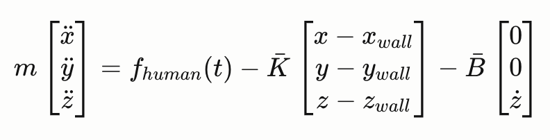
The full 3D vector equation of motion is:
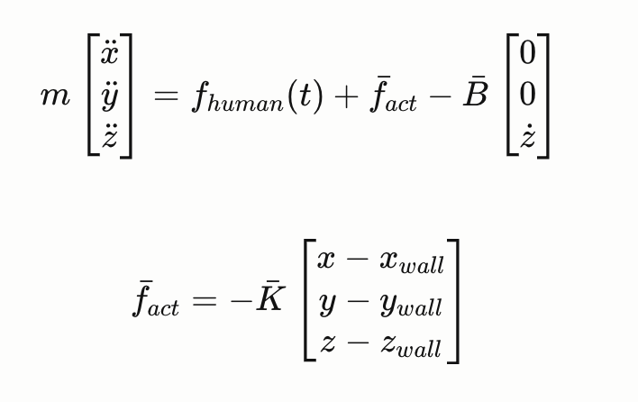
where fact is the actuator force rendered by the impedance controller
The displacement vector is provided by the virtual environment (MuJoCo contact data).
Substituting fact :
Transfer Function (Laplace Domain):
Taking the Laplace transform and treating fhuman(t) as an external input:

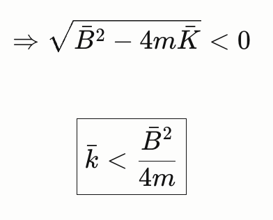
Stability Condition:
The poles of the system are:

Oscillations occur when the poles have an imaginary part. Therefore the stability condition is:
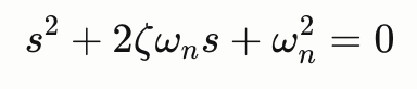
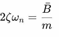
Natural Frequency and Damping Ratio:
Referencing the standard 2nd order form:
Natural frequency:
Damping ratio: From comparison,
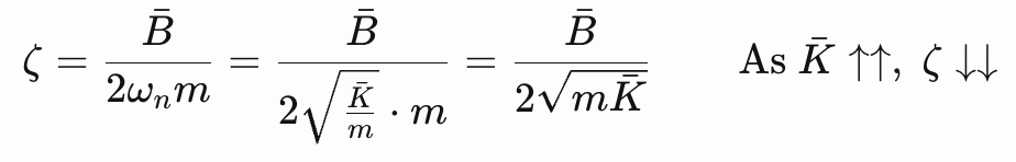
Substituting the stability bound K:
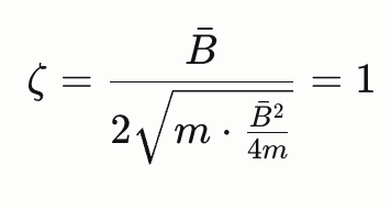
So as K decreases below the bound, ζ > 1 --> the system becomes overdamped.
For this project, we aim to operate close to the stability bound K̅ to ensure stability while rendering enough force for user feedback during collision with the peg hole rim (better haptic fidelity).
Checkpoint 2
Checkpoint 2 (May 21): Finalized feasible top pick for physical attachment. System architecture finalized with MuJoCo virtual environment being setup.
Hardware Status Updates
Building on the design framework established in Checkpoint 1, we have now finalized three distinct handle attachment designs in CREO Parametric, all of which will be 3D printed using PLA filament on a Bambu Lab printer. These attachments are designed to slide over the Touch stylus and enclose the handle by approximately 3 inches, sitting just above the two side buttons on the device. This mounting approach requires no modification to the Touch hardware and ensures a secure, repeatable fit across all conditions. The study compares four conditions in total. The first is the bare Touch stylus with no attachment — this serves as the true baseline and represents how the device is used out of the box. The remaining three conditions each involve a different attachment geometry: a plain cylinder, a disk-topped peg, and a ball-topped peg. Together, these four conditions form a shape fidelity spectrum, allowing us to isolate the effect of handle geometry on haptic realism and task performance independently of other variables. The motivation behind this design is grounded in the concept of passive haptic augmentation — the idea that physically holding an object whose shape matches what you are manipulating in a virtual environment improves the sense of realism and embodied control, even without any change to the force feedback rendered by the device. In a peg-in-hole task, the user is virtually grasping and inserting a peg, yet the physical object in their hand is a generic stylus. By replacing that stylus grip with an attachment that resembles an actual peg, we hypothesize that users will experience stronger haptic congruence between their physical and virtual actions, leading to measurable improvements in task performance and perceived realism.

Proposed Handle Designs: CREO Rendering
The three attachment geometries were chosen deliberately to test how the specific shape of the handle influences these outcomes. The plain cylinder (Image 3) represents a neutral, geometrically simple grip — it adds bulk and length consistent with the other attachments but introduces no distinctive form cue. The disk-topped design (Image 1) mimics a traditional industrial peg with a flanged cap, giving the user a clear top-of-peg reference that may improve orientation awareness during insertion. The ball-topped design (Image 2) introduces a rounded, ergonomic grip that differs from a literal peg shape but may offer comfort advantages or alter how users approach the insertion axis. By comparing all three against the no-attachment baseline, we can assess not only whether passive haptic augmentation helps in general, but which geometric feature — if any — drives the most benefit. This produces a richer, more generalizable finding than a simple two-condition comparison would allow. All three attachments share the same internal bore and length, ensuring that the distance from the user's grip point to the virtual tool-center-point remains consistent across conditions. This was a deliberate design constraint carried forward from Checkpoint 1 to eliminate geometry-driven confounds and ensure that any performance differences observed between conditions can be attributed to handle shape rather than differences in lever arm or grip height. The attachments will be used in a within-subjects study where each participant completes peg-in-hole insertion trials under all four conditions in counterbalanced order, with task completion time, error rate, and subjective realism ratings recorded as the primary outcome measures.
Software Status Updates
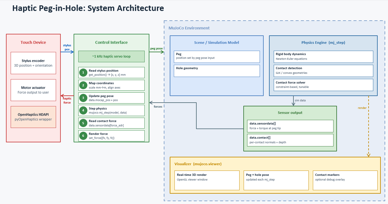
The proposed system integrates a 3D Systems Touch haptic device with the MuJoCo physics engine to simulate a peg-in-hole task with force feedback. The architecture consists of three main components connected through a real-time control bridge running at approximately 1 kHz.
- On each loop iteration, the Control Interface reads the stylus position from the Touch device via the OpenHaptics HDAPI, maps those coordinates into the MuJoCo world frame, and updates the peg's pose in the virtual environment.
- MuJoCo then steps the simulation, resolving contact dynamics between the peg and hole geometry using a constraint-based solver, and the resulting contact forces are read back from a force/torque sensor site attached to the peg tip.
- These forces are then commanded back to the Touch device's motor actuator, closing the haptic feedback loop and allowing the user to physically feel the contact forces during insertion.
The MuJoCo viewer runs in parallel to provide real-time 3D visualization of the scene, including optional contact force markers for debugging.